2. 中国舰船研究院,北京 100192
2. China Ship Research and Development Academy, Beijing 100192, China
混响是海底、海面的不平整性和海水中随机分布的不均匀性散射引起的,是伴随着发射声信号而产生的,与发射基阵、发射信号参数和传播信道的特性有关。近年来,浅海混响一直是水声研究的一个活跃而有意义的研究领域。浅海混响以海底混响为主,主要是由海底散射引起的,因此在进行浅海混响强度估算时通常只考虑海底散射而忽略海面和体积散射的影响。目前为止,关于浅海混响的理论模型主要有射线模型、简正波混响模型[1]、射线简正波混响模型[2]、抛物方程混响模型[3]、波数积分混响模型[4]等。浅海远程混响由于复杂的多途特性,宜用简正波方法计算;浅海近程混响由于不需考虑复杂的多途效应,射线理论更为适用,且简单有效、方便实用,易于分析声源和接收器的指向特性以及测试信号参数对混响的作用。
针对浅海近程声学特性测试,本文采用射线声学计算方法计算浅海典型声速条件下声源传播到海底散射源和散射声压在接收器处的近程混响强度,分析声速垂直分布、声源深度和信号参数对浅海混响的影响,为浅海水声试验及其方案设计提供参考。
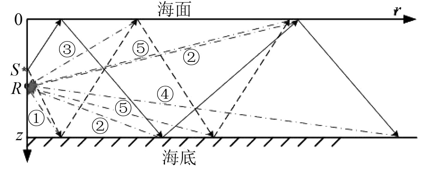
1 浅海近程海底混响强度序列计算海底混响过程包括声源到海底散射源的传播过程、海底散射源散射过程以及散射源到接收器的过程。由于计算的是浅海近程混响,海水水平非均匀的影响较小,不考虑复杂的多途效应,只考虑二次海底反射以内近程混响强度贡献较大的声线,这些声线主要包括:1)声源-海底-接收器;2)声源-海面-海底-接收器(和声源-海面-海底-海面-接收器);3)声源-海底-海面-接收器;4)声源-海面-海底-海面-海底-接收器(和声源-海面-海底-海面-海底-海面-接收器);5)声源-海底-海面-海底-接收器(和声源-海底-海面-海底-海面-接收器)。浅海近程海底界面散射如图1所示。
|
图 1 浅海近程海底界面散射示意图 Fig. 1 The sketch of short range bottom scatter in shallow water |
假定声速(折射率)不随水平方向变化,仅是海水深度的函数;在计算距离范围内,海底平整,即给定某一时刻对海底混响有贡献的有效散射面形成的是一个规则的圆环;声源和接收器的位置静止不变。在分层介质条件下,对于给定声速分布函数
1)声源-海底-接收器的声程和传播时间为:
| ${r_1} = \int_{{z_0}}^{{z_b}} {\frac{{\cos {\theta _0}{\rm d}z}}{{\sqrt {n_0^2(z) - {{\cos }^2}{\theta _0}} }}} + \int_{{z_b}}^{{z_r}} {\frac{{\cos {\theta _{bs}}{\rm d}z}}{{\sqrt {n_b^2(z) - {{\cos }^2}{\theta _{bs}}} }}} {\text{,}}$ | (1) |
| ${t_1}\! \!=\! \!\frac{1}{{{c_0}}}\int_{{z_0}}^{{z_b}} \!{\frac{{n_0^2(z){\rm d}z}}{{\sqrt {n_0^2(z) - {{\cos }^2}{\theta _0}} }}} \!\!+\!\! \frac{1}{{{c_b}}}\int_{{z_b}}^{{z_r}} \!\!{\frac{{n_b^2(z){\rm d}z}}{{\sqrt {n_b^2(z) - {{\cos }^2}{\theta _{bs}}} }}} {\text{。}}\!\!$ | (2) |
2)声源-海面-海底-接收器的声程和传播时间为:
| $\begin{split}{r_2} = & \int_{{z_0}}^{{z_s}} {\frac{{\cos {\theta _0}{\rm d}z}}{{\sqrt {n_0^2(z) - {{\cos }^2}{\theta _0}} }}} + \int_{{z_s}}^{{z_b}} {\frac{{\cos {\theta _s}{\rm d}z}}{{\sqrt {n_s^2(z) - {{\cos }^2}{\theta _s}} }}} + \\& \int_{{z_b}}^{{z_r}} {\frac{{\cos {\theta _{bs}}{\rm d}z}}{{\sqrt {n_b^2(z) - {{\cos }^2}{\theta _{bs}}} }}} {\text{,}}\end{split}$ | (3) |
| $\begin{split}{t_2} \!=\! & \frac{1}{{{c_0}}}\int_{{z_0}}^{{z_s}} {\frac{{n_0^2(z){\rm d}z}}{{\sqrt {n_0^2(z) - {{\cos }^2}{\theta _0}} }}} \!+\! \frac{1}{{{c_s}}}\int_{{z_s}}^{{z_b}} \!\!{\frac{{n_s^2(z){\rm d}z}}{{\sqrt {n_s^2(z) - {{\cos }^2}{\theta _s}} }}} + \\& \frac{1}{{{c_b}}}\int_{{z_b}}^{{z_r}} {\frac{{n_b^2(z){\rm d}z}}{{\sqrt {n_b^2(z) - {{\cos }^2}{\theta _{bs}}} }}} {\text{。}}\end{split}$ | (4) |
3)声源-海底-海面-接收器的声程和传播时间为:
| $\begin{split}& {r_3} = \int_{{z_0}}^{{z_b}} {\frac{{\cos {\theta _0}{\rm d}z}}{{\sqrt {n_0^2(z) - {{\cos }^2}{\theta _0}} }}} + \int_{{z_b}}^{{z_s}} {\frac{{\cos {\theta _b}{\rm d}z}}{{\sqrt {n_b^2(z) - {{\cos }^2}{\theta _b}} }}} + \\& \int_{{z_s}}^{{z_r}} {\frac{{\cos {\theta _{ss}}{\rm d}z}}{{\sqrt {n_s^2(z) - {{\cos }^2}{\theta _{ss}}} }}} {\text{,}}\end{split}$ | (5) |
| $\begin{split}{t_3} \!=\! & \frac{1}{{{c_0}}}\int_{{z_0}}^{{z_b}} {\frac{{n_0^2(z){\rm d}z}}{{\sqrt {n_0^2(z) \!-\! {{\cos }^2}{\theta _0}} }}} \!+\! \frac{1}{{{c_b}}}\int_{{z_b}}^{{z_s}} \!{\frac{{n_b^2(z){\rm d}z}}{{\sqrt {n_b^2(z) - {{\cos }^2}{\theta _b}} }}} + \\& \frac{1}{{{c_s}}}\int_{{z_s}}^{{z_r}} {\frac{{n_s^2(z){\rm d}z}}{{\sqrt {n_s^2(z) - {{\cos }^2}{\theta _{ss}}} }}} {\text{。}}\end{split}$ | (6) |
4)声源-海面-海底-海面-海底-接收器的声程和传播时间为:
| $\begin{split}{r_4} = & \int_{{z_0}}^{{z_s}} {\frac{{\cos {\theta _0}{\rm d}z}}{{\sqrt {n_0^2(z) - {{\cos }^2}{\theta _0}} }}} + \int_{{z_s}}^{{z_b}} {\frac{{\cos {\theta _{s1}}{\rm d}z}}{{\sqrt {n_s^2(z) - {{\cos }^2}{\theta _{s1}}} }}} + \\& \int_{{z_b}}^{{z_s}} {\frac{{\cos {\theta _{b1}}{\rm d}z}}{{\sqrt {n_b^2(z) - {{\cos }^2}{\theta _{b1}}} }} + \int_{{z_s}}^{{z_b}} {\frac{{\cos {\theta _{s2}}{\rm d}z}}{{\sqrt {n_s^2(z) - {{\cos }^2}{\theta _{s2}}} }}} + } \\& \int_{{z_b}}^{{z_r}} {\frac{{\cos {\theta _{bs}}{\rm d}z}}{{\sqrt {n_b^2(z) - {{\cos }^2}{\theta _{bs}}} }}} {\text{,}}\end{split}$ | (7) |
| $\begin{split}{t_4} \!=\! & \frac{1}{{{c_0}}}\int_{{z_0}}^{{z_s}} \!\!{\frac{{n_0^2(z){\rm d}z}}{{\sqrt {n_0^2(z) - {{\cos }^2}{\theta _0}} }}} \!+\! \frac{1}{{{c_s}}}\!\!\int_{{z_s}}^{{z_b}} \!\!\!{\frac{{n_s^2(z){\rm d}z}}{{\sqrt {n_s^2(z) - {{\cos }^2}{\theta _{s1}}} }}} + \\& \frac{1}{{{c_b}}}\int_{{z_b}}^{{z_s}} \!\!{\frac{{n_b^2(z){\rm d}z}}{{\sqrt {n_b^2(z) - {{\cos }^2}{\theta _b}} }} \!+\!\! \frac{1}{{{c_s}}}\int_{{z_s}}^{{z_b}} \!\!{\frac{{n_s^2(z){\rm d}z}}{{\sqrt {n_s^2(z) - {{\cos }^2}{\theta _{s2}}} }}} \!+ } \\& \frac{1}{{{c_b}}}\int_{{z_b}}^{{z_r}} {\frac{{n_b^2(z){\rm d}z}}{{\sqrt {n_b^2(z) - {{\cos }^2}{\theta _{bs}}} }}} {\text{。}}\end{split}$ | (8) |
5)声源-海底-海面-海底-接收器的声程和传播时间为:
| $\begin{split}{r_5} = & \int_{{z_0}}^{{z_b}} {\frac{{\cos {\theta _0}{\rm d}z}}{{\sqrt {n_0^2(z) - {{\cos }^2}{\theta _0}} }}} + \int_{{z_b}}^{{z_s}} {\frac{{\cos {\theta _{b1}}{\rm d}z}}{{\sqrt {n_b^2(z) - {{\cos }^2}{\theta _{b1}}} }}} + \\& \int_{{z_s}}^{{z_b}} {\frac{{\cos {\theta _s}{\rm d}z}}{{\sqrt {n_b^2(z) - {{\cos }^2}{\theta _s}} }} + \int_{{z_b}}^{{z_r}} {\frac{{\cos {\theta _{bs}}{\rm d}z}}{{\sqrt {n_b^2(z) - {{\cos }^2}{\theta _{bs}}} }}} } {\text{,}}\end{split}$ | (9) |
| $\begin{split}{t_5} \!= & \!\frac{1}{{{c_0}}}\!\! \int_{{z_0}}^{{z_b}} \!\!\!{\frac{{n_0^2(z){\rm d}z}}{{\sqrt {n_0^2(z) - {{\cos }^2}{\theta _0}} }}} \!\!+ \!\!\frac{1}{{{c_b}}}\int_{{z_b}}^{{z_s}} \!\!\!{\frac{{n_b^2(z){\rm d}z}}{{\sqrt {n_b^2(z) - {{\cos }^2}{\theta _{b1}}} }}} + \\& \!\! \frac{1}{{{c_s}}}\!\! \int_{{z_s}}^{{z_b}} \!\!{\frac{{n_s^2(z){\rm d}z}}{{\sqrt {n_s^2(z) - {{\cos }^2}{\theta _s}} }} \!\!\!+\! \!\!\frac{1}{{{c_b}}}\int_{{z_s}}^{{z_r}} \!\!{\frac{{n_b^2(z){\rm d}z}}{{\sqrt {n_b^2(z) - {{\cos }^2}{\theta _{bs}}} }}} }{\text{。}} \!\!\end{split}$ | (10) |
式中:
浅海近程海底混响可以看作发射信号与海底混响强度序列的卷积,则浅海近程混响信号的时域波为:
| $r(t) = S(t) \times I(t){\text{,}}$ | (11) |
| $\begin{split}I(t) & = I\left( {b\left( {\theta ,\varphi } \right),{V_s}\left( {{\theta _s}} \right),{V_b}\left( {{\theta _b}} \right),} \right. \ \left. {{S_b}\left( {{\theta _{bs}}} \right),{S_s}\left( {{\theta _{ss}}} \right),r,\tau } \right)=\\& \int\limits_S {\frac{{{I_0}}}{{r_{ss}^2r_{sr}^2}}\prod\limits_i {{V_{si}}\left( {{\theta _{si}}} \right)\prod\limits_j {{V_{bj}}\left( {{\theta _{bj}}} \right)} } {S_b}\left( {{\theta _{bs}}} \right)} \times \\ & \quad {S_s}\left( {{\theta _{ss}}} \right){b^2}\left( {\theta ,\varphi } \right)dA\left( {r,\tau } \right){\text{。}}\qquad\qquad\qquad\qquad \quad \end{split}$ | (12) |
式中:
| ${V_s}\left( {{\theta _s}} \right) = 1 - 0.45 \cdot {(f \cdot {H_{{\text{平均}}}})^{3/2}} \cdot \cos {\theta _s}{\text{,}}$ | (13) |
式中:f为声波频率,kHz;H平均为海浪平均高度(波谷到波峰),m。
海底反射系数
| $- \ln \left| {{V_b}({\theta _b})} \right| =\!\! \left\{\!\!\!\!\!\! {\begin{array}{*{20}{c}}{\begin{array}{*{20}{l}}{\!\!Q \cdot {\theta _b}},\\{\! - \ln \left| {{V_{b0}}} \right| = const},\!\!\!\!\!\!\!\!\!\!\!\!\end{array}} & {\begin{array}{*{20}{c}}{0 < {\theta _b} < {\theta ^*}},\\{{\theta ^*} < {\theta _b} < \displaystyle\frac{\uppi }{2}}\text{。}\end{array}}\end{array}} \right.$ | (14) |
式中:Q为前段(小掠射角时)海底反射系数随掠射角变化的斜率,与频率有关;θ*为海底等效全反射临界角;Vb0为后段(大掠射角时)海底反射系数。
海底散射系数取经验散射函数:
| ${S_b}\left( {{\theta _{bs}}} \right) = \mu + 10\log \sin \theta \sin {\theta _{bs}}{\text{。}}$ | (15) |
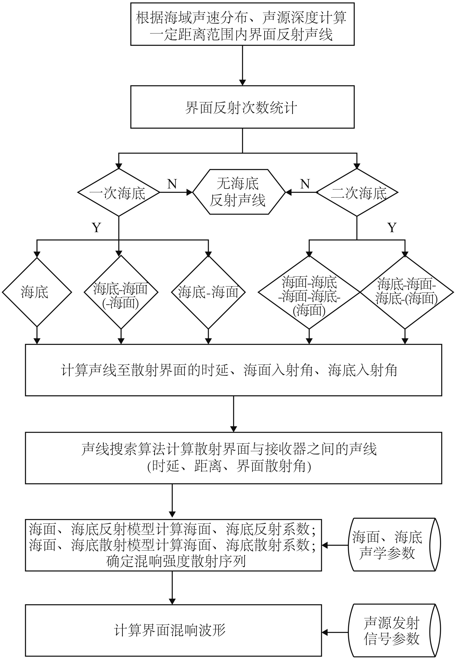
式中:μ为海底散射系数;θ为海底掠射角。浅海近程海底混响时域信号仿真流程如图2所示。
|
图 2 浅海近程海底混响时域信号仿真流程图 Fig. 2 The sketch of short range bottom reverberation in shallow water |
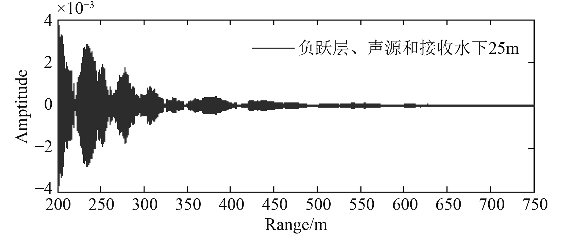
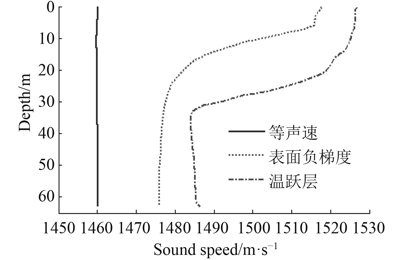
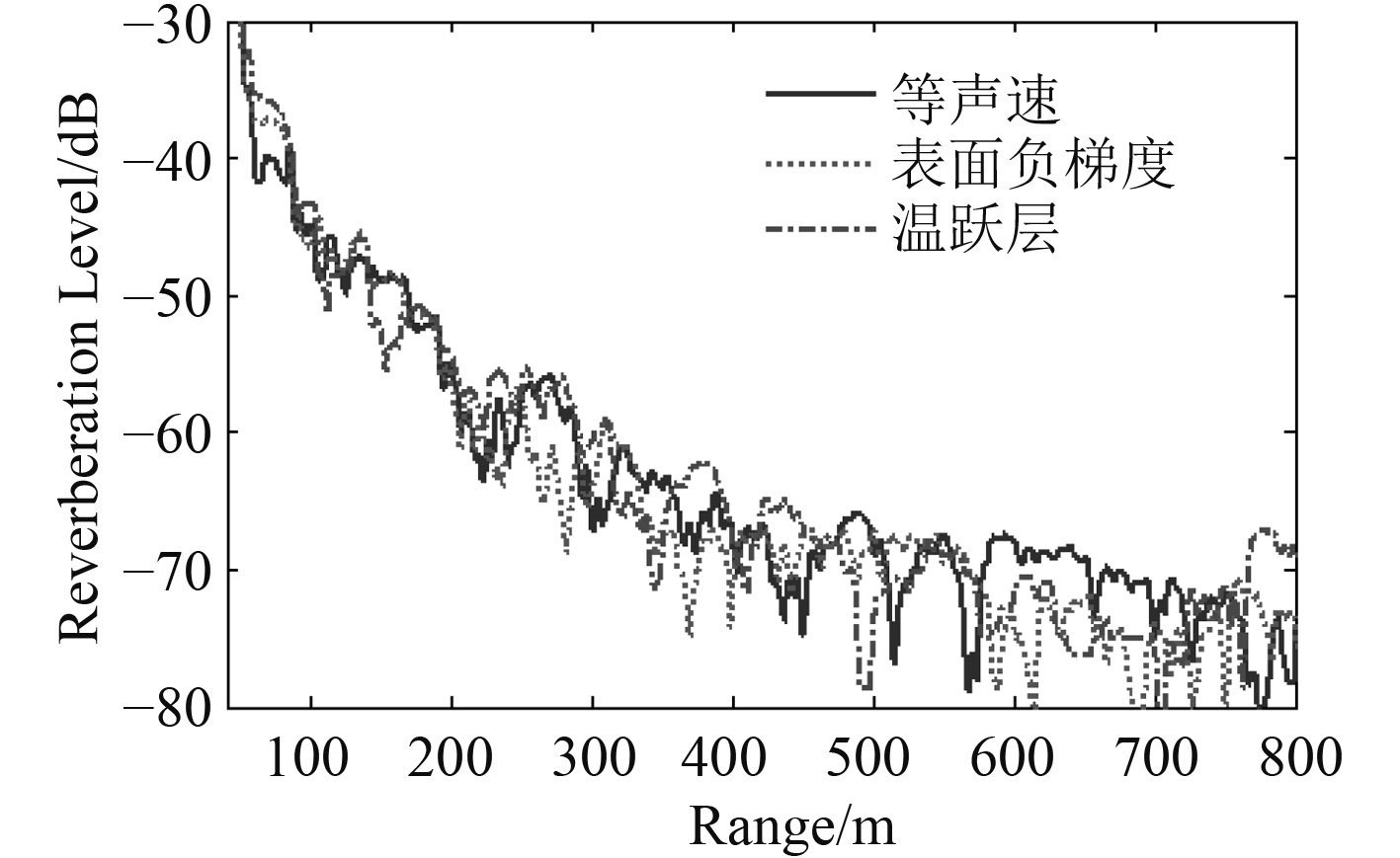
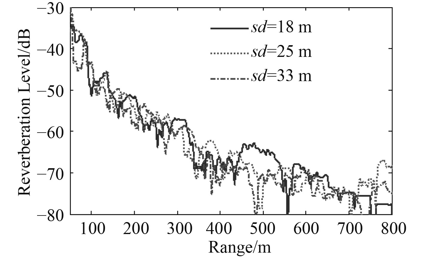
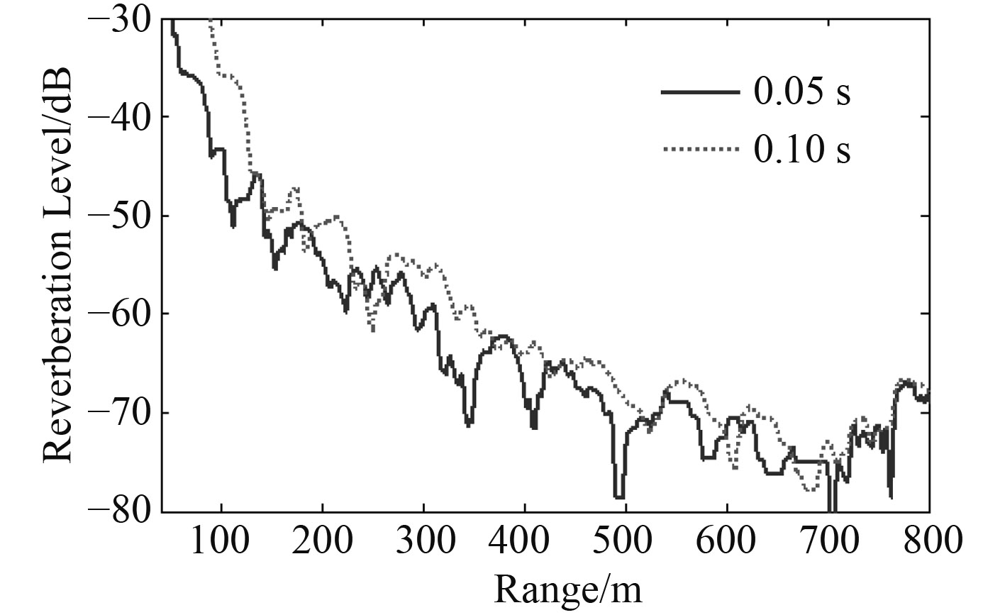
根据上述浅海近程海底混响计算方法和混响时域信号仿真流程,下面给出了浅海典型声速条件下近程混响算例。海深63 m,海水密度为1.03 g/cm3,海底介质密度1.8 g/cm3,海底声速取1 700 m/s,海底散射系数μ取–27 dB,声源长4.8 m,信号为3.0 kHz CW信号,脉宽50 ms,接收水听器深度水下25 m。图3给出了中浅海负跃层声速条件下指向性声源和接收器位于水下25 m时海底混响的时域信号;图4和图5给出了浅海3种典型声速分布下声源位于水下25 m时近程海底混响;图6给出了浅海负跃层声速条件下声源中心分别位于负跃层上方、内部、下方时近程海底混响,图7给出了浅海负跃层声速条件下脉宽50 ms和100 ms CW信号的近程海底混响。
|
图 3 声源和接收位于负跃层时浅海近程海底混响时域信号 Fig. 3 Near distance bottom reverberation time signal when source and receiver in thermocline |
|
图 4 浅海典型声速分布 Fig. 4 Typical sound speed profiles in shallow sea |
|
图 5 浅海不同声速条件下近程海底混响对比 Fig. 5 Contrast of near distance bottom reverberation between different sound speed profiles in shallow sea |
|
图 6 浅海负跃层声源不同深度近程海底混响对比 Fig. 6 Contrast of near distance bottom reverberation between different source depth in shallow thermocline sea |
|
图 7 浅海负跃层不同脉宽信号近程海底混响对比 Fig. 7 Contrast of near distance bottom reverberation between different pulse width in shallow thermocline sea |
由图中可看出:浅海近程混响强度随着时间或距离振荡衰减,不同声速条件下混响强度具有相似的衰减特性。在负跃层声速条件下,声源位于负跃层上方、内部和下方时的混响强度也具有类似的衰减特性,浅海近程混响振荡衰减的“波峰”和“波谷”会随着声速分布、声源深度变化而变化。信号脉宽的增加将导致这种振荡衰减的“波峰”和“波谷”产生滞后,随着信号脉宽和距离的增加,混响衰减特性将趋于平缓。从射线声学来讲,等温层条件下的混响衰减可以认为是不同散射元散射信号的相干引起的;而表面负梯度和负跃层条件下的混响衰减可以认为是由于声线的弯曲导致不同散射元的入射声线不均匀引起的。文献[5 – 6]分别采用射线简正波相干混响理论和波束位移射线简正波解释了负跃层条件下混响强度振荡衰减现象和传播特性。
因此,在浅海进行水下声学试验时,可根据试验海域声速分布、声源方向性进行混响波形和混响强度数值计算,选择合适的声源和接收器布放深度,降低浅海海底混响对声学测试的影响。
3 结 语本文基于射线声学理论,选取对浅海近程海底混响有主要贡献的声线对浅海等温层、表面负梯度和负跃层3种声速分布下的海底混响以及负跃层声速条件下声源位于跃变层上方、内部、下方时的海底混响时域信号和混响强度进行了数值计算。由计算结果可以看出,浅海近程混响强度随着时间或距离振荡衰减,不同声速以及负跃层声速声源不同深度条件下混响强度具有相似的衰减特性,但振荡衰减的“波峰”和“波谷”会随着声速分布、声源深度变化而变化。
| [1] | ELLIS D D. A shallow-water normal-mode reverberation model[J].JASA, 1995, 97: 2804–2814. DOI: 10.1121/1.411910 |
| [2] | 李凤华, 金国亮, 张仁和. 浅海相干混响理论与混响强度的振荡现象[J].中国科学A辑, 2000, 30(6). |
| [3] | KEVIN B, SMITH and WILLIAM S. HODGKISS, Propagation and analysis issues in the prediction of long-range reverberation[J].JASA, 1996, 99(3): 1387–1404. DOI: 10.1121/1.414718 |
| [4] | HENRIK S, KUPERMAN W A. Spectral representation of rough interface reverberation in stratified ocean waveguides[J].JASA, 1995, 97(4): 2199–2209. DOI: 10.1121/1.411945 |
| [5] | 李凤华, 刘建军, 李整林, 等. 浅海低频混响的振荡现象及其物理解释[J].中国科学G辑, 2005, 30(2). |
| [6] | 张林, 范培勤, 徐国军. 浅海负跃层对声传播影响的仿真研究[J].声学技术, 2013, 32(6). |
 2017, Vol. 39
