船舶设备性能的好坏对整个航运的安全影响重大,而船用主海水泵作为非常重要的冷却和供水设备,其地位至关重要[1-3]。本文从实际应用需求出发,设计了一种新型船舶主海水泵变频控制系统,并给出了软硬件设计方法,最后给出了控制界面的设计原理图。
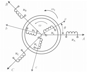
1 船用主海水泵变频异步电机的控制系统三相异步电机是主海水泵中的核心部件,其原理如图 1所示,图中详细描述了定子和转子绕组的分布情况,转子的三相绕组用a,b,c表示,三相定子绕组由A,B,C表示,定子A相的轴线和转子a相的轴线之间的夹角用θ表示,转子的角速度用ω表示,并且以逆时针为正方向,ω1为定子和磁场的相对同步角速度。

|
图 1 三相异步电机原理图 Fig. 1 Diagram of three -phase asynchronous motor |
下面建立三相异步电机的电压关系方程,每个线圈绕组之间的电压平衡方程矩阵为
| $\left[\! \!\!{\begin{array}{*{20}{c}} {{\boldsymbol{u}_{{ABC}}}}\\ {{\boldsymbol{u}_{{abc}}}} \end{array}}\!\!\! \right]\!=\!\left[\!\! {\begin{array}{*{20}{c}} {{\boldsymbol{R}_{s}}}\;\;\;\;\boldsymbol{0}\\ \boldsymbol{0}\;\;\;\;{{\boldsymbol{R}_{r}}} \end{array}} \!\!\!\right]\left[ \!\!\!{\begin{array}{*{20}{c}} {{\boldsymbol{i}_{{ABC}}}}\\ {{\boldsymbol{i}_{{abc}}}} \end{array}} \!\!\!\!\right] + {p}\left[\!\!\! {\begin{array}{*{20}{c}} {{\boldsymbol{L}_{s}}}\;\;\;\;{{\boldsymbol{M}_{{sr}}}}\\ {{\boldsymbol{M}_{{rs}}}}\;\;\;\;{{\boldsymbol{L}_{r}}} \end{array}} \!\!\!\right]\left[\! \!\!{\begin{array}{*{20}{c}} {{\boldsymbol{i}_{{ABC}}}}\\ {{\boldsymbol{i}_{{abc}}}} \end{array}}\!\!\! \right]\text{,}$ | (1) |
式中,
| $\begin{array}{l} {\boldsymbol{u}_{{ABC}}} = \left[ {\begin{array}{*{20}{c}} {{u_{A}}}\\ {{u_{B}}}\\ {{u_{C}}} \end{array}} \right]\text{,}\;\;\;\;\;\;{\boldsymbol{u}_{{\rm{abc}}}} = \left[ {\begin{array}{*{20}{c}} {{u_{a}}}\\ {{u_{b}}}\\ {{u_{c}}} \end{array}} \right]\text{,}\\ {\boldsymbol{i}_{{\rm{ABC}}}} = \left[ {\begin{array}{*{20}{c}} {{i_{A}}}\\ {{i_{B}}}\\ {{i_{C}}} \end{array}} \right]\text{,}\;\;\;\;\;\;\;\;\;{\boldsymbol{i}_{{\rm{abc}}}} = \left[ {\begin{array}{*{20}{c}} {{i_{a}}}\\ {{i_{b}}}\\ {{i_{c}}} \end{array}} \right]\text{。} \end{array}$ | (2) |
式中:
| ${\boldsymbol{R}_{\rm{s}}} = \left[ {\begin{array}{*{20}{c}} {{R_{\rm{1}}}}&0&0\\ 0&{{R_{\rm{1}}}}&0\\ 0&0&{{R_{\rm{1}}}} \end{array}} \right],\;\;\;\;\;\;{\boldsymbol{R}_{\rm{r}}} = \left[ {\begin{array}{*{20}{c}} {{R_{\rm{2}}}}&0&0\\ 0&{{R_{\rm{2}}}}&0\\ 0&0&{{R_{\rm{2}}}} \end{array}} \right]\text{。}$ | (3) |
假设,
| ${\boldsymbol{L}_{s}} = \left[ {\begin{array}{*{20}{c}} {{L_1}}&{{M_{\rm{1}}}}&{{M_{\rm{1}}}}\\ {{M_{\rm{1}}}}&{{L_1}}&{{M_{\rm{1}}}}\\ {{M_{\rm{1}}}}&{{M_{\rm{1}}}}&{{L_1}} \end{array}} \right],\;\;\;{\boldsymbol{L}_{r}} = \left[ {\begin{array}{*{20}{c}} {{L_{\rm{2}}}}&{{M_{\rm{2}}}}&{{M_{\rm{2}}}}\\ {{M_{\rm{2}}}}&{{L_{\rm{2}}}}&{{M_{\rm{2}}}}\\ {{M_{\rm{2}}}}&{{M_{\rm{2}}}}&{{L_{\rm{2}}}} \end{array}} \right]\text{。}$ | (4) |
再用
| ${\boldsymbol{M}_{{sr}}}\!=\!\boldsymbol{M}_{{rs}}^{\rm{T}} \!=\! {M_{{\rm{12}}}}\left[\!\!\!\! {\begin{array}{*{20}{c}} {\cos \theta }\;\;\;\;{\cos (\theta + \frac{{2{\rm{\text{ }\!\!\pi\!\!\text{ } }}}}{3})}\;\;\;\;{\cos (\theta - \frac{{2{\rm{\text{ }\!\!\pi\!\!\text{ } }}}}{3})}\\[8pt] {\cos (\theta - \frac{{2{\rm{\text{ }\!\!\pi\!\!\text{ } }}}}{3})}\;\;\;\;{\cos \theta }\;\;\;\;{\cos (\theta + \frac{{2{\rm{\text{ }\!\!\pi\!\!\text{ } }}}}{3})}\\[8pt] {\cos (\theta + \frac{{2{\rm{\text{ }\!\!\pi\!\!\text{ } }}}}{3})}\;\;\;\;{\cos (\theta - \frac{{2{\rm{\text{ }\!\!\pi\!\!\text{ } }}}}{3})}\;\;\;\;{\cos \theta } \end{array}}\!\!\!\! \right]\text{。}$ | (5) |
由于三相异步电机的电压关系满足微分方程,因此可以写成
| $\boldsymbol{u} = \boldsymbol{Ri} + {p}(\boldsymbol{Li}{\rm{)}}\text{。}$ | (6) |
式中, u , i 分别表示异步电机的电压和电流向量。
| $\begin{array}{l} \boldsymbol{u} = \left[ {\begin{array}{*{20}{c}} {{\boldsymbol{u}_{{\rm{ABC}}}}}\\ {{\boldsymbol{u}_{{\rm{abc}}}}} \end{array}} \right]{\rm{,}}\;\;\;\boldsymbol{i} = \left[ {\begin{array}{*{20}{c}} {{\boldsymbol{i}_{{\rm{ABC}}}}}\\ {{\boldsymbol{i}_{{\rm{abc}}}}} \end{array}} \right]\text{,}\\ \boldsymbol{R} = \left[ {\begin{array}{*{20}{c}} {{\boldsymbol{R}_{\rm{s}}}}&\boldsymbol{0}\\ \boldsymbol{0}&{{\boldsymbol{R}_{\rm{r}}}} \end{array}} \right]{\rm{,}}\;\;\;\boldsymbol{L} = \left[ {\begin{array}{*{20}{c}} {{\boldsymbol{L}_{\rm{s}}}}&{{\boldsymbol{M}_{{\rm{sr}}}}}\\ {{\boldsymbol{M}_{{\rm{rs}}}}}&{{\boldsymbol{L}_{\rm{r}}}} \end{array}} \right]\text{。} \end{array}$ | (7) |
式中, R , L 分别表示异步电机的电阻和电感矩阵。
下面计算电磁转矩Tem:
| ${T_{{em}}} \!=\! \frac{{{p_0}}}{2}{\boldsymbol{i}^{\rm{T}}}\frac{{\partial \boldsymbol{L}}}{{\partial \theta }}\boldsymbol{i} \!=\! \frac{{{p_0}}}{2}[{\boldsymbol{i}_{{ABC}}}\;{\boldsymbol{i}_{{abc}}}]\left[\!\!\! {\begin{array}{*{20}{c}} \boldsymbol{0}&{\frac{{\partial {\boldsymbol{M}_{{\rm{sr}}}}}}{{\partial \theta }}}\\ {\frac{{\partial {\boldsymbol{M}_{{\rm{rs}}}}}}{{\partial \theta }}}&\boldsymbol{0} \end{array}}\!\!\! \right]\left[\!\!\! {\begin{array}{*{20}{c}} {{\boldsymbol{i}_{{ABC}}}}\\ {{\boldsymbol{i}_{{abc}}}} \end{array}} \right]\text{。}$ | (8) |
观察发现,上述的转子运动方程也属于非线性的微分方程[5-6]。
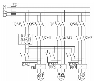
如图 2所示为电机的变频控制原理图,控制器通过开关器KM2,KM4和KM6用于控制变频器的输出组合,进一步对水泵M1\M2\M3进行调整,变频器通过与电力网络连接,实现3台主海水泵的自由工作组合,从而实现变频控制。

|
图 2 变频控制原理图 Fig. 2 Frequency conversion control schematic diagram |
本文设计的变频控制系统硬件平台采用8051微处理器为主控制器,并采用TI公司生产的TMS320LF 2407 A作为系统的控制核心,然后根据具体的应用需求,搭建了电压整流电路、滤波电路、逆变驱动电路、光电隔离电路、监测电路、过压保护电路和人机扩展接口电路等。
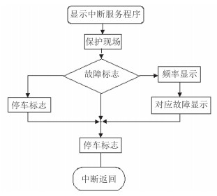
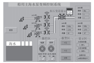
2.2 软件设计为了实现良好的人机互动,本文设计了人性化的软件操控界面,同时针对软件控制系统,设计了中断服务程序,如图 3所示。通过服务中断程序,能够显著增强系统的兼容能力和稳定性。设计的软件操作界面如图 4所示,能够完成变频控制、状态显示和预警等功能。

|
图 3 软件服务中断程序 Fig. 3 Software service interrupt routine |

|
图 4 控制界面 Fig. 4 Control interface |
对于船舶主海水泵的控制一直都是船舶工业领域的研究重点,人们通过各种先进的单片机控制技术,能够显著的提高控制系统的性能,同时正如本文做的工作一样,实现了远程的软件操控,有利于船员进一步降低工作强度。
| [1] | 赵天怡, 张吉礼, 马良栋. 供热空调系统并联变频水泵转速比配置优化分析[J]. 大连理工大学学报, 2011 (5): 701–706. |
| [2] | 曲凯阳, 胡德祥, 王连吉, 等. 中央空调冷却水泵变频节能的讨论[J]. 建筑热能通风空调, 2009 (5): 82–84, 77. |
| [3] | 俞震华. GW级机组凝结水泵变频运行性能分析[J]. 中国电力, 2010 (7): 53–56. |
| [4] | WEBER G, RIESENBERG K, SCHLAEFFER F, et al. Changing trends in frequency and antimicrobial resistance of urinary pathogens in outpatient clinics and a hospital in Southern Israel, 1991-1995[J]. European Journal of Clinical Microbiology & Infectious Diseases, 1998, 1611 : 1450–1453. |
| [5] | ZHANG Qiang, GU Xi-hui, VIJAY P S, et al. Flood frequency under the influence of trends in the Pearl River basin, China:changing patterns, causes and implications[J]. Hydrol. Process., 2005, 296 : 675–680. |
| [6] | INSUP L, ABHIK B. Behavior of the S-phase of plasma nitrocarburized 316L austenitic stainless steel on changing pulse frequency and discharge voltage at fixed pulse-off time[J]. Surface & Coatings Technology, 2016, 235 : 1236–1240. |
 2017, Vol. 39
