2. 中国船舶重工集团公司第七一四研究所,北京 100101 ;
3. 中国石油天然气股份有限公司北京油气调控中心,北京 100012
2. The 714 Research Institute of CSIC, Beijing 100101, China ;
3. Beijing Oil and Gas Control Center, Beijing 100012, China
潜艇作为海军重要的作战武器,对于维护国家海权、协同水面舰船作战、进行战略威慑具有重要意义[1]。获取潜艇水动力系数是评价其操纵性的重要途径。计算流体力学(CFD)作为重要的途径,可以节省经费、缩短研究周期,且由于获得的水动力系数越来越准确,故越来越受到认可。
文献[2-5]以 Suboff 模型为研究对象对潜艇定常 运动进行了计算,分析了网格和湍流模型对计算精度的影响,并获得了部分线型和非线性水动力系数。文献[6]通过MRF方法将回转运动计算转化为定常计算,并进行了数值模拟,分析了回转运动的原理。文献[7-9]通过自编程序对回转运动进行了研究,分析了湍流模型、网格结构、边界层等对计算精度的影响。
以上文献涉及到的数值计算均是基于固联于艇体的运动坐标系,并将非定常问题通过 UDF 功能转化为定常计算。本文以潜艇 Suboff 模型为研究对象,基于大地坐标系,借助刚性网格方法和 Mesh Motion 功能,通过流体计算软件 Fluent,对潜艇直航阻力运动、水平面和垂直面变漂角运动、悬臂回转运动进行数值计算,并将计算得到的水动力系数与试验值进行对比,验证方法的有效性和准确性。
1 基本理论与控制方程 1.1 ALE 方程在很多运动物体模拟中,几何体的运动可以分解为整个计算域的刚体运动和局部位置的相对运动的叠加。本文用 ALE 方程来描述这种计算域的刚性运动。其在直角坐标系下的积分形式为:
| $\frac{\partial }{\partial t}\iiint\limits_{\Omega }{\vec{Q}\text{d}V}+\iint_{\partial \text{ }\Omega }{\vec{F}(\vec{Q})}\cdot \vec{n}\text{d}S=0,$ | (1) |
式中的解向量为:
| $\vec{Q}={{(\rho ,\rho u,\rho v,\rho w,\rho e)}^{\text{T}}}$ | (2) |
对流通量矢量项
| $\begin{align} & {{{\vec{F}}}_{x}}(\vec{Q})=\left\{ \begin{matrix} \rho {{U}_{n}} \\ \rho u{{U}_{n}}+p \\ \rho v{{U}_{n}} \\ \rho w{{U}_{n}} \\ (e+p){{U}_{n}}+{{x}_{t}}p \\ \end{matrix} \right\},{{{\vec{F}}}_{y}}(\vec{Q})=\left\{ \begin{matrix} \rho {{V}_{n}} \\ \rho u{{V}_{n}} \\ \rho v{{V}_{n}}+p \\ \rho w{{V}_{n}} \\ (e+p){{V}_{n}}+{{y}_{t}}p \\ \end{matrix} \right\}, \\ & {{{\vec{F}}}_{z}}(\vec{Q})=\left\{ \begin{matrix} \rho {{W}_{n}} \\ \rho u{{W}_{n}} \\ \rho v{{W}_{n}} \\ \rho w{{W}_{n}}+p \\ (e+p){{W}_{n}}+{{z}_{t}}p \\ \end{matrix} \right\}\text{.} \\ \end{align}$ | (3) |
式中:Ω 为控制体,∂Ω 为控制体单元的边界;dV 为体积微元;
对一些特殊的运动形式可以将物体作为刚性物体处理,此时,计算域网格作为刚性网格与物体固连,所以不用在每个时间步重新生成新的网格,基于 ALE 方程便可描述计算域的运动形式。刚性运动网格计算方法与固定计算域相比只是在通量计算时考虑了网格的运动速度。网格运动速度和网格在每个时刻点的位置由如下方法确定。
设物体的转动轴的方程为:
| $\frac{{x - {x_0}}}{A} = \frac{{y - {y_0}}}{B} = \frac{{z - {z_0}}}{C} = t\,$ | (4) |
设网格 i 中心点的坐标为
| $x = ({x_i} - {x_n})\cos (a(t)) + ({z_i} - {z_n})\sin (a(t)) + {x_n}\,$ | (5) |
| $y = {y_i}\,$ | (6) |
| $z=-({{x}_{i}}-{{x}_{n}})\sin (a(t))+({{z}_{i}}-{{z}_{n}})\cos (a(t))+{{z}_{n}}.$ | (7) |
水动力系数数值计算通过以下数值试验实现:直航阻力数值试验、垂直面变漂角数值试验、水平面变漂角数值试验。通过 Suboff 模型,利用 Fluent 软件实现各种运动。
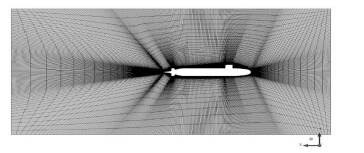
2.1 数值计算的准备通过专业网格划分软件 ICEM CFD,采用全局映射式六面体网格离散方法建立网格。计算区域的大小是:距离潜艇前部有 1 L 距离,尾部有 2 L 距离,上下左右为 1 L 距离。根据 RNG k-ε 湍流模型对于近壁面网格处理方法的要求,Y+ 主要集中在(0,10),网格数目为 360 万。

|
图 1 计算域网格截面图 Fig. 1 Mesh graph of computational domain |
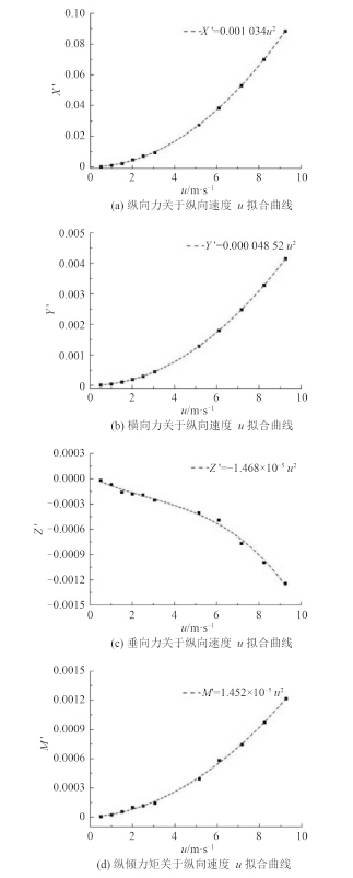
根据纵向直航阻力试验的特点设定计算域运动速度 u0 = 0.5 m/s,1 m/s,2 m/s,2.5 m/s,3.045 m/s,5.144 m/s,6.091 m/s,7.160 m/s,8.230 m/s,9.254m/s,Turbulent Intensity 和 Turbulent Viscosity Ratio 均设定为 1%。根据直航阻力运动特点,u = u0,v = 0,w = 0,p = 0,q = 0,r = 0,则六自由度空间运动方程[10]可简化为:
| $X\text{=}\frac{1}{2}\rho {{L}^{2}}{{{{X}'}}_{uu}}{{u}^{2}},\text{Y=}\frac{1}{2}\rho {{L}^{2}}{{{{Y}'}}_{0}}{{u}^{2}},Z\text{=}\frac{1}{2}\rho {{L}^{2}}{{{{Z}'}}_{0}}{{u}^{2}},M\text{=}\frac{1}{2}\rho .{{L}^{3}}{{{{M}'}}_{0}}{{u}^{2}}.$ | (8) |
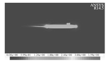
其中 u,v,w,p,q,r 分别为计算域横向速度、纵向速度、垂向速度、横倾角速度、纵倾角速度及偏航角速度。通过 Matlab 对计算结果进行二次样条线拟合如图 2 所示。图 3 是流场的速度剖面图。

|
图 2 直航阻力数值试验拟合曲线 Fig. 2 Fitted curves of direct resistance numerical experiments |

|
图 3 流场纵剖面速度分布图 Fig. 3 The longitudinal velocity distribution of flow field |
通过计算不同攻角条件下潜艇的受力和力矩,可推算相关水动力系数。假定潜艇的速度为 U = 3.045 m/s,攻角 α 为 ± 2°,± 4°,± 6°,± 8°,± 10°,± 12°,± 15°,± 20°,± 25°,则计算域速度
由于 Suboff 模型对称性,故 Y0′ = 0,K0′ = 0,N0′ = 0。而 Mww′ 数值较小可约等于 0。垂向力 Z 和纵倾力矩 M 关于垂向速度 w 的函数为:
| $\left\{ \begin{array}{*{35}{l}} Z(w)\text{=}{{Z}_{0}}\text{+}{{Z}_{w}}w\text{+}{{Z}_{w\text{ }\!\!|\!\!\text{ }w\text{ }\!\!|\!\!\text{ }}}w\text{ }\!\!|\!\!\text{ }w\text{ }\!\!|\!\!\text{ ,} \\ M(w)\text{=}{{M}_{0}}\text{+}{{M}_{w}}w\text{+}{{M}_{w\text{ }\!\!|\!\!\text{ }w\text{ }\!\!|\!\!\text{ }}}w\text{ }\!\!|\!\!\text{ }w\text{ }\!\!|\!\!\text{ }\text{.} \\ \end{array} \right.$ | (9) |
Z、M 关于不同速度 w 可得如下方程组:
| $\left\{ \begin{align} & \sum\limits_{i}{({{Z}_{0}}\text{+}{{Z}_{w}}}w\text{+}{{Z}_{w\text{ }\!\!|\!\!\text{ }w\text{ }\!\!|\!\!\text{ }}}w\text{ }\!\!|\!\!\text{ }w\text{ }\!\!|\!\!\text{ -}{{\text{Z}}_{i}})\text{=0}, \\ & \sum\limits_{i}{({{Z}_{0}}\text{+}{{Z}_{w}}w\text{+}{{Z}_{w\text{ }\!\!|\!\!\text{ }w\text{ }\!\!|\!\!\text{ }}}w\text{ }\!\!|\!\!\text{ }w\text{ }\!\!|\!\!\text{ -}{{\text{Z}}_{i}}){{\text{w}}_{i}}\text{=0}}, \\ & \sum\limits_{i}{({{Z}_{0}}\text{+}{{Z}_{w}}w\text{+}{{Z}_{w\text{ }\!\!|\!\!\text{ }w\text{ }\!\!|\!\!\text{ }}}w\text{ }\!\!|\!\!\text{ }w\text{ }\!\!|\!\!\text{ -}{{\text{Z}}_{i}}){{\text{w}}_{i}}\text{ }\!\!|\!\!\text{ }{{\text{w}}_{i}}\text{ }\!\!|\!\!\text{ =0}}, \\ & \sum\limits_{i}{({{\text{M}}_{0}}\text{+}{{\text{M}}_{w}}}w\text{+}{{\text{M}}_{w\text{ }\!\!|\!\!\text{ }w\text{ }\!\!|\!\!\text{ }}}w\text{ }\!\!|\!\!\text{ }w\text{ }\!\!|\!\!\text{ -}{{\text{M}}_{i}})\text{=0}, \\ & \sum\limits_{i}{({{\text{M}}_{0}}\text{+}{{\text{M}}_{w}}}w\text{+}{{\text{M}}_{w\text{ }\!\!|\!\!\text{ }w\text{ }\!\!|\!\!\text{ }}}w\text{ }\!\!|\!\!\text{ }w\text{ }\!\!|\!\!\text{ -}{{\text{M}}_{i}}){{\text{w}}_{i}}\text{=0}, \\ & \sum\limits_{i}{({{\text{M}}_{0}}\text{+}{{\text{M}}_{w}}}w\text{+}{{\text{M}}_{w\text{ }\!\!|\!\!\text{ }w\text{ }\!\!|\!\!\text{ }}}w\text{ }\!\!|\!\!\text{ }w\text{ }\!\!|\!\!\text{ -}{{\text{M}}_{i}}){{\text{w}}_{i}}\text{ }\!\!|\!\!\text{ }{{\text{w}}_{i}}\text{ }\!\!|\!\!\text{ =0}\text{.} \\ \end{align} \right.$ | (10) |
解方程组并进行无因次化,可得水动力系数。
2.4 水平面变漂角数值试验假定潜艇的速度为 U = 3.045 m/s,漂角 β 为 ± 2°,± 4°,± 6°,± 8°,± 10°,± 12°,± 14°,± 16°,由垂直面变漂角 β 试验特点可知,u ≠ 0,v ≠ 0,w = 0,p = 0,q = 0,r = 0。计算域运动速度
由于 Suboff 模型对称性,故 Y0′ = 0,N0′ = 0。横向力 Y 和偏航力矩 N 关于横向速度 v 的函数为:
| $\left\{ \begin{array}{*{35}{l}} Y(v)={{Y}_{v}}v+{{Y}_{v\text{ }\!\!|\!\!\text{ }v\text{ }\!\!|\!\!\text{ }}}v\text{ }\!\!|\!\!\text{ }v\text{ }\!\!|\!\!\text{ }, \\ N(v)={{N}_{v}}v+{{N}_{v\text{ }\!\!|\!\!\text{ }v\text{ }\!\!|\!\!\text{ }}}v\text{ }\!\!|\!\!\text{ }v\text{ }\!\!|\!\!\text{ }\text{.} \\ \end{array} \right.$ | (11) |
Y,N 关于不同速度 v 可得如下方程组:
| $\left\{ \begin{align} & \sum\limits_{i}{({{Y}_{v}}v}+{{Y}_{v\text{ }\!\!|\!\!\text{ }v\text{ }\!\!|\!\!\text{ }}}v\text{ }\!\!|\!\!\text{ }v\text{ }\!\!|\!\!\text{ -}{{Y}_{i}})\text{=0}, \\ & \sum\limits_{i}{({{Y}_{v}}v\text{+}{{Y}_{v\text{ }\!\!|\!\!\text{ }v\text{ }\!\!|\!\!\text{ }}}v\text{ }\!\!|\!\!\text{ }v\text{ }\!\!|\!\!\text{ -}{{Y}_{i}}){{\text{v}}_{i}}\text{=0}}, \\ & \sum\limits_{i}{({{Y}_{v}}v\text{+}{{Y}_{v\text{ }\!\!|\!\!\text{ }v\text{ }\!\!|\!\!\text{ }}}v\text{ }\!\!|\!\!\text{ }v\text{ }\!\!|\!\!\text{ -}{{Y}_{i}}){{\text{v}}_{i}}\text{ }\!\!|\!\!\text{ }{{\text{v}}_{i}}\text{ }\!\!|\!\!\text{ =0}}, \\ & \sum\limits_{i}{({{N}_{v}}v}\text{+}{{N}_{v|v|}}v|v|-{{N}_{i}})\text{=0}, \\ & \sum\limits_{i}{({{N}_{v}}}v+{{N}_{v|v|}}v|v|-{{N}_{i}}){{v}_{i}}=0, \\ & \sum\limits_{i}{({{N}_{v}}}v+{{N}_{v|v|}}v|v|-{{N}_{i}}){{v}_{i}}|{{v}_{i}}\text{ }\!\!|\!\!\text{ =0}\text{.} \\ \end{align} \right.$ | (12) |
解方程组并进行无因次化,可得水动力系数。
|
|
表 1 基于刚性网格法的数值试验水动力导数 Tab.1 Hydrodynamic coefficients of numerical experiments based on rigid grid |
通过直航阻力数值试验及水平面变漂角数值试验获得的水动力导数计算结果误差为 3.7%,满足计算工程需求。通过垂直面变漂角数值试验获得的水动力导数计算结果误差为 7%,这是由于当攻角较大时,通过湍流模型计算不能准确捕捉到流动分离;而且全附体潜艇大攻角运动时,潜艇指挥台围壳导致背流区分离,而且有主附体干扰的存在,同时指挥台围壳对流场的干扰也会对翼产生影响,影响舵效及伴流场。
3 结 语本文根据每种运动的不同,对潜艇六自由度空间运动方程进行化简,获得了直航阻力运动、垂直面变漂角运动、水平面变漂角运动的空间运动方程。利用 Suboff 模型,基于刚性网格法,通过设定计算域的运动形式,实现了潜艇直航阻力运动、垂直面变漂角运动、水平面变漂角运动的数值模拟,通过对计算结果进行拟合得到了线性水动力系数和非线性水动力系数,通过与相关试验结果进行对比可知,计算误差在 7% 左右。
| [1] |
肖昌润, 刘瑞杰, 许可, 等. 潜艇旋臂回转试验数值模拟[J]. 江苏科技大学(自然科学版) , 2014, 28 (4) :313–316.
XIAO Chang-run, LIU Rui-jie, XU Ke, et al. Simulation for submarine rotating-arm tests[J]. Journal of Jiangsu University of Science and Technology (Natural Science Edition) , 2014, 28 (4) :313–316. |
| [2] |
刘志华, 熊鹰, 韩宝玉. 潜艇流场数值计算网格与湍流模型选取[J]. 华中科技大学学报(自然科学版) , 2009, 37 (7) :98–101.
LIU Zhi-hua, XIONG Ying, HAN Bao-yu. Computational grid and turbulent model for calculating submarine viscous flow field[J]. Journal of Huazhong University of Science and Technology(Natural Science Edition) , 2009, 37 (7) :98–101. |
| [3] |
孙铭泽, 王永生, 张志宏, 等. 基于网格变形技术的全附体潜艇操纵性计算[J]. 武汉理工大学学报(交通科学与工程版) , 2013, 37 (2) :420–424.
SUN Ming-ze, WANG Yong-sheng, ZHANG Zhi-hong, et al. Numerical simulation of submarine maneuverability based on mesh deformation technology[J]. Journal of Wuhan University of Technology (Transportation Science & Engineering) , 2013, 37 (2) :420–424. |
| [4] |
柏铁朝, 梁中刚, 周轶美, 等. 潜艇操纵性水动力数值计算中湍流模式的比较与运用[J]. 中国舰船研究 , 2010, 5 (2) :22–28.
BAI Tie-chao, LIANG Zhong-gang, ZHOU Yi-mei, et al. Comparison and application of turbulence modes in submarine maneuvering hydrodynamic forces computation[J]. Chinese Journal of Ship Research , 2010, 5 (2) :22–28. |
| [5] |
吴方良, 吴晓光, 许建, 等. 全附体潜艇三维粘性流场数值计算方法研究[J]. 船舶工程 , 2009, 31 (4) :8–12.
WU Fang-liang, WU Xiao-guang, XU Jian, et al. Study on numerical calculation method of the 3D viscous flow field over a submarine with full appendages[J]. Ship Engineering , 2009, 31 (4) :8–12. |
| [6] |
刘帅, 葛彤, 赵敏. 基于源项法的潜艇旋臂试验模拟[J]. 大连海事大学学报 , 2011, 37 (2) :1–4.
LIU Shuai, GE Tong, ZHAO Min. Simulation for submarine rotating-arm test based on added momentum source method[J]. Journal of Dalian Maritime University , 2011, 37 (2) :1–4. |
| [7] | GREGORY P A, JOUBERT P N, CHONG M S. Flow over a body of revolution in a steady turn[R]. Rockingham: Defence Science and Technology Organisation Victoria Platform Science Lab, 2004. http://cn.bing.com/academic/profile?id=294202416&encoded=0&v=paper_preview&mkt=zh-cn |
| [8] | TOXOPEUS S, ATSAVAPRANEE P, WOLF E, et al. Collaborative CFD exercise for a submarine in a steady turn[C]//Proceedings of the OMAE ASME 31st International Conference on Ocean Offshore and Arctic Engineering. Rio de Janeiro: ASME, 2012: 761-772. |
| [9] | MARSHALLSAY P G, ERIKSSON A M. Use of computational fluid dynamics as a tool to assess the hydrodynamic performance of a submarine[C]//Australasian Fluid Mechanics Conference. Launceston, 2012. |
| [10] | 施生达. 潜艇操纵性[M]. 北京: 国防工业出版社, 1995 . |
| [11] | PAN Y C, ZHANG H X, ZHOU Q D. Numerical prediction of submarine hydrodynamic coefficients using CFD simulation[J]. Journal of Hydrodynamics, Series B , 2012, 24 (6) :840–847. DOI:10.1016/S1001-6058(11)60311-9 |
 2016, Vol. 38
