2. 中国人民解放军61139部队, 福建 漳州 363000
2. No.61139 Unit of PLA, Zhangzhou 363000, China
为了将旋臂试验这一非定常问题转换为定常问题求解,需要将绝对速度下的N-S方程转化为相对速度下的N-S方程。N-S方程可以表示为:
| $ {GBK}{song} \rho \frac{{\text{d}U}}{{\text{d}t}} = \rho f + \nabla \left\{ { - p{\boldsymbol{\delta}} + \mu (\nabla U + \frac{1}{3}{{(\nabla U)}^\text{T}})} \right\}\text{。} $ | (1) |
式中:ρ为密度;t为时间;U为绝对速度矢量;f为微元体体积力;p为压力;δ为单位矩阵;μ为动力粘度。
根据速度合成定理,将绝对速度U分解为相对速度Ur和牵连速度Ue,即U=Ur+Ue,Ur=[u, v, w]T。在旋转坐标系下,
| $ \frac{{{\rm{d}}{U_r}}}{{{\rm{d}}t}} = \frac{{{{\rm{d}}^2}x'}}{{{{\rm{d}}^2}t}}i' + \frac{{{{\rm{d}}^2}y'}}{{{{\rm{d}}^2}t}}j' + \frac{{{{\rm{d}}^2}z'}}{{{{\rm{d}}^2}t}}k' + \mathit{\Omega} \times {U_r}{\rm{, }} $ | (2) |
| $ \frac{{{\rm{d}}{U_e}}}{{{\rm{d}}t}} = a \times r' + \frac{{{\rm{d}}V}}{{{\rm{d}}t}} + \mathit{\Omega} \times (\mathit{\Omega} \times r' + V) + \mathit{\Omega} \times U。 $ | (3) |
式中:a为牵连运动的角加速度,记
| $ \begin{aligned} \rho \frac{{{\rm{d}}U}}{{{\rm{d}}t}} = & \rho f + \nabla \left\{ { - p{\boldsymbol{\delta}} + \mu (\nabla {U_r} + \frac{1}{3}{{(\nabla {U_r})}^{\rm{T}}})} \right\} + \\ & \mu {\nabla ^2}{U_e} + \frac{1}{3}\mu \nabla {({U_e})^{\rm{T}}} - \rho \frac{{{\rm{d}}{U_e}}}{{{\rm{d}}t}}\text{,} \end{aligned} $ | (4) |
牵连速度Ue只是时间的函数,所以
| $ \rho {a_r} \!=\! \rho f \!+\! \nabla \left\{ { - p{\boldsymbol{\delta}} \!+\! \mu (\nabla {U_r} \!+\! \frac{1}{3}{{(\nabla {U_r})}^\text{T}})} \right\} - \rho {a_e} - \rho {a_c}\text{。} $ | (5) |
控制方程采用时均的连续方程和N-S方程,并且采用湍流模型RNG k-ε和标准k-ε使控制方程封闭,借以考察2种模型对潜艇旋臂试验数值仿真精度。下面给出2种模型的数学表达式,详细推导过程和各参数选取可参考文献[12]。
1)RNG k-ε模型
湍动能k方程:
| $ \frac{{\partial (\rho k)}}{{\partial t}} + \frac{{\partial (\rho k{u_i})}}{{\partial {x_i}}} = \frac{\partial }{{\partial {x_j}}}[{\alpha _k}{\mu _{eff}}\frac{{\partial k}}{{\partial {x_j}}}] + {G_k} + \rho \varepsilon\text{;} $ | (6) |
湍耗散率ε方程:
| $ \frac{{\partial (\rho \varepsilon )}}{{\partial t}} + \frac{{\partial (\rho \varepsilon {u_i})}}{{\partial {x_i}}} = \frac{\partial }{{\partial {x_j}}}[{\alpha _\varepsilon }{\mu _{eff}}\frac{{\partial \varepsilon }}{{\partial {x_j}}}] + \frac{{C_{1\varepsilon }^*}}{k}{G_k} - {C_{2\varepsilon }}\rho \frac{{{\varepsilon ^2}}}{k}\text{。} $ | (7) |
2)标准k-ω模型
湍动能k方程:
| $ \begin{aligned} \frac{\partial }{{\partial t}}(\rho k) + \frac{\partial }{{\partial {x_i}}}(\rho {u_i}k) = & {\tau _{ij}}\frac{{\partial k}}{{\partial {x_j}}} - {\beta ^*}\rho \omega k + \\ & \frac{\partial }{{\partial {x_j}}}[(\mu + {\sigma ^*}{\mu _t})\frac{{\partial k}}{{\partial {x_j}}}] + {S_k}\text{;} \end{aligned} $ | (8) |
特殊耗散率ω方程:
| $ {GBK}{song} \begin{aligned} \frac{\partial }{{\partial t}}(\rho \omega ) + \frac{\partial }{{\partial {x_i}}}(\rho {u_i}\omega ) = & [(\mu + \sigma {\mu _t})\frac{{\partial \omega }}{{\partial {x_j}}}] + \\ & a\frac{\omega }{k}{\tau _{ij}}\frac{{\partial {u_i}}}{{\partial {x_j}}} - \beta \rho {\omega ^2} + {S_k}\text{。} \end{aligned} $ | (9) |
以上2种模型均采用有限体积法(FVM)对控制方程和湍流模型进行离散,压力速度耦合迭代采用SIMPLEC算法,动量方程、湍流动能方程、耗散率方程采用二阶迎风格式,考虑计算收敛性,采用欠松弛技术,速度欠松弛因子、湍动能松弛因子、特殊耗散率松弛因子均取0.3,其他默认。残差收敛均取为0.000 1。
2 模拟模型与网格划分 2.1 模拟对象以Suboff AFF-8潜艇模型为数值模拟对象,模型主尺度L=4.356 m,其中前体长1.016 m,平行中体长2.229 m,后体长1.111 m,最大直径为0.508 m,裸艇为去除围壳和十字舵的主艇体部分,模型如图 1所示。

|
图 1 Suboff AFF-8潜艇模型 Fig. 1 Submarine model of Suboff AFF-8 |
本文2种计算下边界条件相同,计算域为一包裹潜艇的圆环,最外半径为26 m,最内半径为10 m,艇体力矩中心与文献[11]一致。域内流体为不可压缩水介质,不考虑重力,计算域模型和边界条件如图 2所示。

|
图 2 计算域模型(a)和边界条件(b)示意图 Fig. 2 Computational domain model(a)and the boundary conditions(b) |
环形流场壁面设置为静止壁面边界,其他默认;潜艇壁面设置为随区域运动的壁面边界,旋转中心为(0,0,0),旋转轴为(0,0,1),相对于临近网格单元静止。
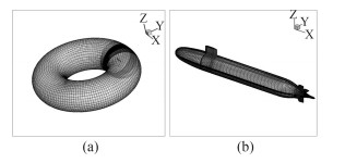
2.3 网格划分结构网格能够节省大量的内存空间,拥有更高的计算效率,本文采用分块网格技术划分结构网格。运用商业网格划分软件ICEM CFD对潜艇外流场进行网格划分,其中,裸艇网格数量为45万,全附体网格数量为150万,划分方法类似。仅以裸艇体网格划分为例:由2 D Planar旋转拉伸为10个块,每个块旋转角度为36°。全局缩放因子选1,在全局单元尺寸为1的基础上对局部进行加密。潜艇周围划分外O-Block,以便边界层处理,边界层内单元增长率为1:1.1;边界层到流场边界单元增长率为1:1.2,在其他地方采用H型网格,确保网格质量在0.6以上。边界层内节点数设为31,第1层网格高度为0.1 mm,使壁面Y+值在30左右,选用标准壁面函数;边界层到边界节点数设为25,艇首部节点数设置为26,艇尾部节点数为31,对应与弧度部分特殊加密,平行中体处节点数为46。网格划分结果如图 3所示。

|
图 3 流场网格(a)和全附体潜艇表面网格(b)示意图 Fig. 3 Grids of the flow field(a)and the surface of fully enclosed submarine(b) |
水动力系数为无因次化结果,力和力矩旋转导数无因次化表达式为:
| $ {Y'_r} = \frac{{{Y_r}}}{{0.5\rho V{L^3}}}, \; \;\; {N'_r} = \frac{{{N_r}}}{{0.5\rho V{L^4}}}\text{。} $ | (10) |
式中:ρ为液态水密度,ρ=998;V为潜艇旋转线速度;L为潜艇垂线间长,按文献[11]取L=4.261 m;Yr为Y向受力;Nr为Z轴力矩,力矩中心与文献一致,本文中为(0,18,0),整个计算区域设置为旋转坐标系,坐标系的旋转角速度r分别为0.1 rad/s,0.2 rad/s,0.3 rad/s,0.4 rad/s,0.5 rad/s。以裸艇在标准k-ω模型下计算结果为例,图 4分别为流场Z=0切面(角速度为0.2 rad/s时)的速度云图和压力云图,其中速度云图单位为m/s,压力云图单位为Pa。从图中可看出速度、压力分布与半径呈线性关系。图 5为裸艇和全附体潜艇周围流场速度云图,从图中可看到潜艇尾流迹,与事实相符。

|
图 4 流场Z=0切面速度云图(a)和压力云图(b) Fig. 4 Velocity cloud picture(a)and pressure cloud picture(b)when Z=0 |

|
图 5 裸艇(a)和全附体潜艇(b)周围流场速度云图 Fig. 5 Velocity cloud picture around purified submarine(a)and fully enclosed submarine(b) |
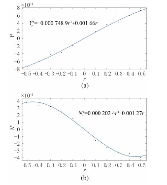
在同一艇型和湍流模型下,得到不同角速度的力与力矩值,将其无因次化后,通过Matlab三次样条曲线进行拟合,得到拟合方程后求其在r=0处斜率即为所求水动力系数。图 6为裸艇在标准k-ω湍流模型下角速度r(rad/s)分别与横向力旋转导数Yr'、转首力矩旋转导数Nr'的拟合曲线,其他拟合结果以表格给出。表 1为裸艇拟合结果与试验结果对比,表 2为全附体潜艇拟合结果与试验结果对比。

|
图 6 横向力旋转导数(a)和转首力矩旋转导数(b)拟合曲线 Fig. 6 Curve graph of lateral rotary derivative and yawing moment rotary derivative |
|
|
表 1 裸艇拟合结果与试验结果对比 Tab.1 Comparison between simulations and experiments in purified submarine |
|
|
表 2 全附体潜艇拟合结果与试验结果对比 Tab.2 Comparison between simulations and experiments in fully enclosed submarine |
从表中可看出,旋转坐标系方法对横向力旋转导数Yr'的计算结果明显好于转首力矩旋转导数Nr',这是因为旋臂试验中潜艇每一点的速度大小和方向都应确定,而数值模拟却与潜艇位置相关,这会造成Nr'误差较大,这也是此方法的局限之一,对仿真结果总结如下:
1)在对裸艇和全附体潜艇的计算模拟中,标准k-ω模型精度要高于RNG k-ε模型,Yr'的精度能够达到工程要求;
2)计算用时较短(单个计算用时不足2 h),计算效率高于文献[5]的滑移网格,在精度要求不高的情况下,对旋转导数的模拟能够较好的预测其趋势,体现了基于旋转坐标系方法的优势。
4 结语本文通过Suboff裸艇与全附体在2种湍流模型下,运用旋转坐标系方法对其旋转导数进行仿真模拟,并与试验数据相比,验证了该方法的可行性。标准的仿真结果总体好于RNG,在精度要求不高的情况下,该方法具有较高的计算效率。本文的研究内容对潜艇旋转导数求取有一定参考价值。
| [1] |
王超, 郑小龙, 李亮, 等. Y+值对潜艇流场大涡模拟计算精度的影响[J]. 华中科技大学学报(自然科学版) , 2015, 43 (4) :79–83.
WANG Chao, ZHENG Xiao-long, LI Liang, et al. Influence of Y+ on the calculation of submarine flow field characteristics of LES calculation accuracy[J]. Journal of Huazhong University of Science and Technology (Natural Science Edition) , 2015, 43 (4) :79–83. |
| [2] |
张楠, 沈泓萃, 姚惠之. 潜艇阻力与流场的数值模拟与验证及艇型的数值优化研究[J]. 船舶力学 , 2005, 9 (1) :1–13.
ZHANG Nan, SHEN Hong-cui, Yao Hui-zhi. Validation of numerical simulation on resistance and flow field of submarine and numerical optimization of submarine hull form[J]. Journal of Ship Mechanics , 2005, 9 (1) :1–13. |
| [3] |
潘子英, 吴宝山, 沈泓萃. CFD在潜艇操纵性水动力工程预报中的应用研究[J]. 船舶力学 , 2004, 8 (5) :42–51.
PAN Zi-ying, WU Bao-shan, SHEN Hong-cui. Research of CFD application in engineering estimation of submarine maneuverability hydrodynamic forces[J]. Journal of Ship Mechanics , 2004, 8 (5) :42–51. |
| [4] |
涂海文, 孙江龙. 基于CFD的潜艇阻力及流场数值计算[J]. 舰船科学技术 , 2012, 34 (3) :19–25.
TU Hai-wen, SUN Jiang-long. Numerical analysis of resistance and flow field of submarine based on CFD[J]. Ship Science and Technology , 2012, 34 (3) :19–25. |
| [5] |
肖昌润, 刘瑞杰, 许可, 等. 潜艇旋臂回转试验数值模拟[J]. 江苏科技大学学报(自然科学版) , 2014, 28 (4) :313–316.
XIAO Chang-run, LIU Rui-jie, XU Ke, et al. Simulation for submarine rotating-arm tests[J]. Journal of Jiangsu University of Science and Technology (Natural Science Edition) , 2014, 28 (4) :313–316. |
| [6] |
刘帅, 葛彤, 赵敏. 基于源项法的潜艇旋臂试验模拟[J]. 大连海事大学学报 , 2011, 37 (2) :1–4.
LIU Shuai, GE Tong, ZHAO Min. Simulation for submarine rotating-arm test based on added momentum source method[J]. Journal of Dalian Maritime University , 2011, 37 (2) :1–4. |
| [7] |
王骁, 蔡烽, 石爱国, 等. 双桨双舵舰船旋臂试验粘性流场数值模拟方法研究[J]. 船舶力学 , 2014, 18 (7) :786–793.
WANG Xiao, CAI Feng, SHI Ai-guo, et al. Numerical simulation of the viscous flow over the ship with twin-propellers and twin-rudders in rotating arm tests[J]. Journal of Ship Mechanics , 2014, 18 (7) :786–793. |
| [8] |
黄成涛.浅水中作回转运动船体粘性绕流计算[D].武汉:华中科技大学, 2007.
HUANG Cheng-tao. Numerical calculate for viscous flow about a swirling ship in shallow water[D]. Wuhan:Huazhong University of Science and Technology, 2007. |
| [9] |
林俊兴, 倪刚, 戴余良, 等. 潜艇定常回转运动参数变化规律研究[J]. 舰船科学技术 , 2014, 36 (1) :31–33.
LIN Jun-xing, NI Gang, DAI Yu-liang, et al. Research on parameters' change rule of submarine's steady rotary movement[J]. Ship Science and Technology , 2014, 36 (1) :31–33. |
| [10] |
胡志强, 林扬, 谷海涛. 水下机器人粘性类水动力数值计算方法研究[J]. 机器人 , 2007, 29 (2) :145–150.
HU Zhi-qiang, LIN Yang, GU Hai-tao. On numerical computation of viscous hydrodynamics of unmanned underwater vehicle[J]. Robot , 2007, 29 (2) :145–150. |
| [11] | RODDY R F. Investigation of the stability and control characteristics of several configurations of the DARPA SUBOFF model (DTRC Model 5470) from captive-model experiments[R]. Washington D.C:David Taylor Research Center, 1990. |
| [12] |
王福军.
计算流体动力学分析-CFD软件原理与应用[M]. 北京: 清华大学出版社, 2006 .
WANG Fu-jun. Computational fluid dynamics analysis-the theory and application of CFD software[M]. Beijing: Tsinghua University Press, 2006 . |
 2016, Vol. 38
