 2016, Vol. 59


2. 65185部队, 辽宁铁岭 112611
2. Unit 65185 PLA, Tieling 112611, China
磁张量系统可以实现对目标的定位和识别(Gamey et al.,2004; Nara et al.,2006; Stolz et al.,2006; 李光等,2012),为目标探测提供有效手 段.近年来磁张量理论以及磁张量系统已经成为国内外研究热点.磁张量系统一般需要搭载到机动载体上进行探测,由于机动载体多由钢铁等铁磁性物质组成,铁磁性物质被地球磁场等磁化后具有磁性,对磁张量系统测量会造成一定影响.虽然这些载体在使用前可能进行过相应的消磁处理,但被探测目标磁场属于弱磁场,载体磁场足以将其淹没,载体磁场对磁张量测量是一个不容忽视的干扰源.
载体的磁干扰主要包括硬磁材料产生的固有磁场和软磁材料产生的感应磁场,并且感应磁场的大小和方向会随着载体的位置、姿态的变化而变化.Pei针对水下无人平台研究了磁张量系统载体磁场补偿,以其中一个离载体较远的传感器为参考传感器,以此传感器测量磁场为真实地球磁场,对其他传感器进行载体磁补偿(Pei et al.,2009; Pei et al.,2010).Lü指出Pei的方法中参考传感器虽然离载体较远,但仍然会受到载体磁场干扰.Lü对Pei的方法进行了重新推导,将参考传感器受载体磁场干扰的因素加入其中,建立了更加严密的磁补偿模型(Lü et al.,2013).Lü的方法较Pei的方法有所改进,但仍存在以下三个问题:
(1)其建立的是非线性模型,求解时容易出现多解性和解不稳定现象.
(2)其实质是单个三轴磁传感器的分别补偿,即分体式补偿,对于由非三轴磁传感器构成的磁张量系统难以适用.
(3)校正参数过多,达48个.为此本文提出了一种磁张量系统载体的一体化线性磁补偿方法,该方法只需求解20个磁补偿参数.
2 磁张量系统结构 2.1 磁张量要素磁场是一个矢量场,包括3个分量,其3分量磁场在空间3个方向的变化率即为磁张量,共包括9个值,其表达式为
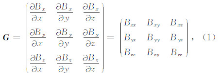
其中 G 为磁张量,Bx、By和Bz为磁场三分量.磁性载体产生的磁场可以看作静磁场,由麦克斯韦方程组可知,描述静磁场的基本方程为(林春生,2003)

其中 H 为磁场强度,B 为磁感应强度,μ为磁导率,σ为空间电流密度.在磁性载体周围空间内,σ=0,μ为常数,故有:div B =0,rot B =0,即

所以式(1)中只有5个要素是独立的,本文为后续计算简便用其中5个独立元素表示磁张量为

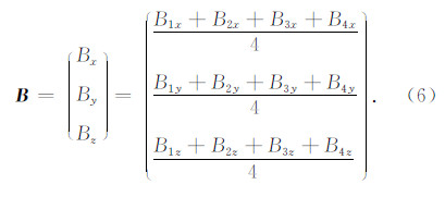
磁张量系统的结构形式有很多,如平面十字形、三角形、正方形、直角四面体和正四面体(刘丽敏,2012).本文以平面十字形的磁张量系统为例阐述本文所提出的载体磁补偿方法,平面十字磁张量系统如图 1所示(张光等,2013).
 | 图 1 平面磁张量系统结构Fig. 1 Structure of planar magnetic tensor system |
图 1中1、2、3和4分别代表一个三轴磁场传感器,传感器对应磁轴相互平行,系统的基线距离为d,用该系统可以测量得到磁性目标的磁场张量值 G和总磁场矢量 B 为

载体通常由大量钢铁构件组成,并且装有电机等驱动设备,这些构件和设备中往往包含硬磁材料和软磁材料,硬磁材料产生固有磁场,软磁材料产生感应磁场.
3.1 载体固有磁场影响硬磁材料是在经受外磁场后能保持大量剩磁的磁性材料,这类磁性材料的特点是矫顽力大,该种材料的磁滞回线所包围的“面积”较大,磁滞特性非常明显,相当于永久磁铁,它产生的磁感应强度可以认为是不变的,不会随着载体姿态或位置的变化而改变,称为固有磁场.
因为这些硬磁材料和磁张量系统都是固联在载体上的,所以不论载体姿态怎样变化硬磁材料所产生的合成磁场在张量系统位置都是不变的.也就是说,固有磁场对磁张量系统的影响相当于增加了一个常矢量偏置,其表达式为

载体固有磁场在短时间内可认为是恒定的常矢量,但当载体长期暴露在地磁场环境中,其固有磁场也会随着时间的增长而不断变化(仲维畅,2004). 当载体在地磁场中因往复的加速运动或高速旋转而引起的磁化-退磁循环次数足够多时,载体上的剩磁最终会在一段时间后发生较大变化.因此,载体在使用一段时间后,需要重新对其固有磁场进行校正.
3.2 载体感应磁场影响软磁材料能够用相对低的磁感应强度磁化,当外磁场移走后保持相对弱的剩磁.该种材料的特点是矫顽力很小,其磁滞回线狭窄,所包围的“面积”较小,当被环境磁场磁化后产生的感应磁场将影响其周围磁场.影响的大小和方向与环境磁场和软磁材料本身有关.
钢铁构件由原子组成,每个原子又由原子核及围绕其转动的电子组成.电子的转动形成电流,称为原子电流.每个原子电流形成一个小的环状电流,在外磁场作用下,各个环状电流将受到磁力矩的作用,这一作用使各环状电流在一定程度上沿着外磁场的方向排列起来,对外显示磁性.软磁材料中的单个原子电流环可用一个磁偶极子来表征(周耀忠和张国友,2004),那么软磁材料的感应磁场可以等效于若干个被磁化的磁偶极子磁场的叠加.由电磁学知识可知,铁磁等材料在外磁场作用下会被磁化产生磁矩,其磁化磁矩与外磁场的强度成正比,那么载体中某磁偶极子的磁化磁矩为(王楚等,2000)
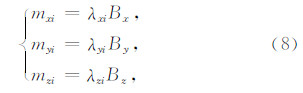
其中Bx,By和Bz为外界磁化磁场;mxi,myi和mzi为被磁化磁偶极子的磁矩;λxi,λyi和λzi为磁化系数,i表示某个磁偶极子的序号.该磁偶极子在磁张量系统所在位置产生的梯度张量值为(吴招才,2008)
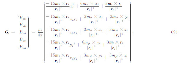
其中 m i=(mxi,myi,mzi)T; r i=(xi,yi,zi)T为磁偶极子到磁张量系统中心的位置矢量.
将式(8)代入式(9),将Bx,By和Bz单独提出来,整理后得

其中cmni(m=1…5,n=1…3)被外磁场磁化产生的磁偶极子,在磁张量探测系统中心产生的磁张量系数.
软磁材料的感应磁场可以等效于若干个磁偶极子磁场的叠加,又由于微分运算符合线性叠加原理,可知磁张量也可以进行线性叠加,那么对于被磁化的软磁性材料整体对外产生的磁张量值可以表示为若干个磁偶极子产生的磁张量值的叠加,即为
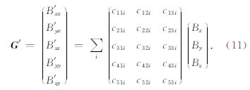
将上式进一步化简得
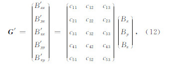
其中cmn(m=1…5,n=1…3)被外磁场磁化的软磁材料,在磁张量探测系统中心产生的磁张量系数; G ′=(B′ xx B′ yx B′ zx B′ yy B′ zy)T为软磁性材料产生的感应磁场对磁张量系统测量张量值的影响.
3.3 载体磁场补偿模型在匀强磁场环境下,磁张量系统测量的磁张量值应当接近零,但由于载体固定磁场和感应磁场的影响使磁张量系统测量值 G ″远远偏离零值,结合式(7)和式(12)得到载体磁场补偿模型为

将上式进一步写为

其中 G ″=(B″ xx B″ yx B″ zx B″ yy B″ zy )T为在匀强磁场环境下,存在载体干扰时磁张量系统的测量值; B =(Bx By Bz)T为无载体情况下,由三个分量磁场组成的感应磁场矢量,由于其也会受到载体硬磁软磁干扰,无法直接测量得到.本文运用杨云涛等提出的载体磁场干扰补偿方法求解 B 如下(杨云涛等,2009):
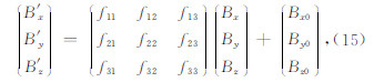
其中 B ′=(B′ x B′ y B′ z)T为受到载体硬磁软磁磁场干扰后测量得到的磁场矢量值,可由式(6)近似得到; B 0=(Bx0 By0 Bz0)T为硬磁材料产生的固有磁场对磁场矢量值的影响;fkj(k=1…3,j=1…3)被外磁场磁化的软磁材料,在磁张量探测系统中心产生的磁张量系数.
将式(15)移项、求逆得到的 B 代入式(14)得:
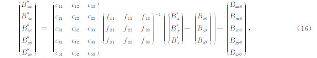
令 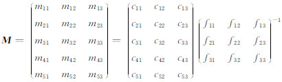 ,则式(16)简写为

再令 G ′ 0=(B′ xx0 B′ yx0 B′ zx0 B′ yy0 B′ zy0)T= G 0- M B 0,则式(17)可进一步化简为

式(18)中的 M和G ′ 0 共含20个未知参数,为载体磁张量补偿系数.只要载体和固连在其上的磁张量系统同时进行4个以上姿态的旋转,将张量测量值 G ″和磁场矢量测量值 B ′代入式(18)即可求解得到载体的20个磁张量补偿系数.当磁张量系统探测目标时,用这20个补偿系数和磁张量系统测量得到的三分量磁场值就可以计算得到载体产生的干扰磁张量值,在磁张量系统测量的总磁张量值中减去载体产生的干扰磁张量值,即可得到目标的磁张量值,实现对磁张量系统载体磁张量补偿.
4 实验验证运用自制的经典式三轴磁通门传感器构成平面磁张量系统,并先完成一系列的系统校正(黄玉和郝燕玲,2012; 张光等,2013,2015),降低磁张量系统固有误差(单个三分量磁传感器三轴非正交性误差、灵敏度不一致 误差、零点偏移误差和4个传感器轴系间对正误差等).
在均匀磁场环境下,将磁张量系统固定在三轴无磁转台上,在一定距离上放置一体积为0.003 m3的铁块模拟载体产生硬磁软磁干扰.磁张量系统连同铁块在转台上进行多姿态旋转(为了增加求解的准确性,进行了10个姿态的旋转),记录各姿态时磁张量系统的测量数据,如表 1所示.运用本文所提出的方法,结合磁张量系统测量数据求解得到模拟载体的20个磁张量补偿系数为

| | 表 1 各姿态下磁张量系统测量数据 Table 1 Measurement data of magnetic tensor system under different attitudes |
为验证补偿效果,在均匀磁场环境下,对磁张量系统及铁块又进行了4个姿态的旋转.利用磁张量系统测量得到的三分量磁场值,以及前面求解得到的20个磁张量补偿系数就可以解算得到铁块产生的磁张量值,如 果该张量值与磁张量系统直接测量得到的磁张量值接近,说明磁补偿系数求解正确,磁补偿方法有效.磁 张量系统测量的三分量磁场值结合磁补偿系数求解得到的磁张量值、直接测量得到的磁张量值如表 2所示.
由表 2可以看到模拟载体所用的铁块对磁张量系统测量值的影响最大达到653 nT/m,超过一般被探测目标所产生的磁张量值,若不对其进行补偿将使磁张量系统难以完成探测.运用本文所提出的方法解算得到的磁张量值与直接测量的磁张量值最大相差为32 nT/m,比较准确地得到了载体对磁张量系统测量值的影响,在一定程度上对载体硬磁软磁影响进行了补偿.
| | 表 2 磁补偿系数解算的磁张量值及直接测量的磁张量值比较 Table 2 Comparison of calculated magnetic tensor using compensation coefficients and directly measured magnetic tensor |
在分析载体固有磁场和感应磁场形成机理的基础上,将载体固有磁场等效为固定磁张量偏置,将载体感应磁场等效为磁偶极子磁张量值的叠加,建立了载体的一体化线性磁张量补偿模型,对模型进行求解,得到20个磁张量补偿系数,当系统探测目标时可利用其对系统进行载体磁张量补偿.实测实验表明,本文所提方法解算得到的磁张量值与载体实际产生的磁张量值仅差32 nT/m,可在一定程度上补偿载体对磁张量系统的影响,证明了本文方法的正确性及有效性.
| [1] | Gamey T J, Doll W E, Beard L P. 2004. Initial design and testing of a full-tensor airborne SQUID magnetometer for detection of unexploded ordnance.//SEG Technical Program Expanded Abstracts. SEG, 798-801. |
| [2] | Huang Y, Hao Y L. 2012. Error correction of magnetic field component gradiometer based on FLANN and least-squares. Chinese Journal of Scientific Instrument(in Chinese), 33(4):911-917. |
| [3] | Li G, Sui Y Y, Liu L M, et al. 2012. Magnetic dipole single-point tensor positioning based on the difference method. Journal of Detection & Control(in Chinese), 34(5):50-54. |
| [4] | Lin C S. 2003. The Physical Field of Ships(in Chinese). Beijing:Ordnance Industry Press. |
| [5] | Liu L M. 2012. Configuration design, error analysis and underwater target detection of fluxgate tensor magnetometer(in Chinese). Changchun:Jilin University. |
| [6] | Lü J W, Yu Z T, Huang J L, et al. 2013. The compensation method of vehicle magnetic interference for the magnetic gradiometer. Advances in Mathematical Physics, 2013:Article ID 523164. |
| [7] | Nara T, Suzuki S, Ando S. 2006. A closed-form formula for magnetic dipole localization by measurement of its magnetic field and spatial gradients. IEEE Transactions on Magnetics, 42(10):3291-3293. |
| [8] | Pei Y H, Yeo H G. 2009. UXO survey using vector magnetic gradiometer on autonomous underwater vehicle.//OCEANS 2009, MTS/IEEE Biloxi-Marine Technology for Our Future:Global and Local Challenges. Biloxi, MS:IEEE, 1-8. |
| [9] | Pei Y H, Yeo H G, Kang X Y, et al. 2010. Magnetic gradiometer on an AUV for buried object detection.//OCEANS 2010. Seattle, WA:IEEE, 1-8. |
| [10] | Stolz R, Zakosarenko V, Schulz M, et al. 2006. Magnetic full-tensor SQUID gradiometer system for geophysical applications. The Leading Edge, 25(2):178-180. |
| [11] | Wang C, Li C, Zhou L Z. 2000. Electromagnetics(in Chinese). Beijing:Beijing University Press, 182-206. |
| [12] | Wu Z C. 2008. Magnetic gradient tensor technology and its application(in Chinese). Wuhan:China University of Geosciences. |
| [13] | Yang Y T, Shi Z Y, Guan Z Z, et al. 2009. A magnetic disturbance compensation method based on magnetic dipole magnetic field distributing theory. Acta Armamentarii(in Chinese), 29(12):1485-1491. |
| [14] | Zhang G, Zhang Y T, Li Z N, et al. 2013. Localizing method of magnetic field gradient tensor under carriers moving parallelly. J. Huazhong Univ. of Sci. & Tech.(Natural Science Edition)(in Chinese), 41(1):21-24. |
| [15] | Zhang G, Zhang Y T, Yin G, et al. 2015. Calibration method of magnetic tensor system based on linear error model. Journal of Jilin University(Engineering and Technology Edition)(in Chinese), 45(3):1012-1016. |
| [16] | Zhong W C. 2004. The self "motion magnetization" of ferro-magnetic object in the earth's magnetic field. Nondestructive Inspection(in Chinese), 28(5):9-10, 14. |
| [17] | Zhou Y Z, Zhang G Y. 2004. The Analysis and Calculation of Ships' Magnetic Field(in Chinese). Beijing:National Defense Industry Press. |
| [18] | 黄玉, 郝燕玲. 2012. 基于FLANN和最小二乘的磁梯度计误差校正. 仪器仪表学报, 33(4):911-917. |
| [19] | 李光, 随阳轶, 刘丽敏等. 2012. 基于差分的磁偶极子单点张量定位方法. 探测与控制学报, 34(5):50-54. |
| [20] | 林春生. 2003. 舰船物理场. 北京:兵器工业出版社. |
| [21] | 刘丽敏. 2012. 磁通门张量的结构设计、误差分析及水下目标探测. 长春:吉林大学. |
| [22] | 王楚, 李椿, 周乐柱. 2000. 电磁学. 北京:北京大学出版社, 182-206. |
| [23] | 吴招才. 2008. 磁力梯度张量技术及其应用研究. 武汉:中国地质大学. |
| [24] | 杨云涛, 石志勇, 关贞珍等. 2009. 一种基于磁偶极子磁场分布理论的磁场干扰补偿方法. 兵工学报, 29(12):1485-1491. |
| [25] | 张光, 张英堂, 李志宁等. 2013. 载体平动条件下的磁梯度张量定位方法. 华中科技大学学报(自然科学版), 41(1):21-24. |
| [26] | 张光, 张英堂, 尹刚等. 2015. 基于线性误差模型的磁张量系统校正. 吉林大学学报(工学版), 45(3):1012-1016. |
| [27] | 仲维畅. 2004. 铁磁性物体在地磁场中的自发"运动磁化". 无损探伤, 28(5):9-10, 14. |
| [28] | 周耀忠, 张国友. 2004. 舰船磁场分析计算. 北京:国防工业出版社. |