重联耗散区的微观物理十分重要.重联耗散区的波动被认为在磁场能量快速释放时担当重要角色(Shay et al., 1999,2001; Birn et al., 2001; Birn and Hesse, 2001; Deng and Matsumoto, 2001; Rogers et al., 2001; Vaivads et al., 2004). 在重联过程中,有许多种等离子体波动被观测到,它们在能量释放时扮演的角色也被深入研究(Rogers et al., 2001; Vaivads et al., 2004).这些波动包括哨声波( M and t et al., 1994; Deng and Matsumoto, 2001)、静电孤立波(Deng et al., 2004,2009; Cattell et al., 2005; Li et al., 2009,2013,2014)、低混杂波(LHW)(Shinohara et al., 1998,2001; Bale et al., 2002; Vaivads et al., 2004; Ji et al., 2004; Zhou et al., 2009)等.
低混杂波由低混杂漂移不稳定性(LHDI)驱动,其波动频率在低混杂频率以下.本文统称之为低混杂波(LHW).低混杂波常常在重联耗散区附近观测到,并被认为在中性片的磁场重联提供反常电阻系数中起到一定的作用,而反常电阻系数对触发(促进)快速磁场重联很重要(Bale et al., 2002; Ji et al., 2004; Zhou et al., 2009).
一般认为LHW主要在重联离子耗散区的边界区域能观测到(Davidson et al., 1977; Bale et al., 2002).但是,最近的模拟和观测结果表明低混杂波的电磁波模可以存在于中心电流片(Shinohara et al., 2001; Daughton,2003).低混杂频率上的电磁波动在实验室快速磁场重联发生装置的薄电流片的中心区域也被观测到(Ji et al., 2004).这些结果表明电磁扰动可能对磁场重联的发展有潜在影响.
有研究表明,电流密度在中心电流片由于受到低混杂漂移不稳定性所诱发而得到增强,这将导致撕裂膜不稳定性的急剧增长,最终导致快速磁场重联的发生和发展(Shinohara and Fujimoto, 2005).一旦低混杂漂移不稳定性饱和了,这个过程就发生. 快速重联撕裂膜的时间尺度与重联系统的最快增长模式相当.基于模拟结果,目前普遍认为当磁场重联充分发 展之后,低混杂漂移不稳定性将消失(Tanaka et al., 2005,2006).
然而,在薄电流片磁场重联耗散区中是否存在低混杂漂移不稳定性及其激发的低混杂波是一个值得讨论的问题.Xiao 等(2007)报导了与三维零点-零点连接线的运动相关的低混杂振荡现象的卫星观测结果.Zhou等(2009)利用Cluster卫星也对重联耗散区进行了波动分析,发现在磁场重联耗散区邻近能观测到静电和电磁模式的低混杂漂移波.Wang等(2010)在接近离子耗散区中心观测到的次级磁岛有强大的核心磁场,在其附近也可以观测到低混杂频率上的波动.然而,上述文献中的观测结果没有详细研究在磁场重联X线临近区域的低混杂波.本文中,我们将提供进一步的证据,表明由低混杂漂移不稳定性驱动的低混杂波在离子耗散区中可以存在,并且,低混杂波在磁场重联充分发展之后仍然非常活跃. 2 磁场重联耗散区穿越的观测
我们将研究近磁尾大约-27 RE处的一个磁场重联区域的低混杂波.Geotail卫星在2005年5月15日在近地磁尾穿越磁场重联耗散 区,该事件已经被Nagai 等(2011)详细阐述.Geotail 从耗散区X-line的尾向北侧直接穿越到地向北侧(参见图 2).最近已经有文献对本事件重联耗散区中的霍尔物理效应以及波动特性做了较为详细的分析(Nagai et al., 2011; Fujimoto et al., 2011; Zenitani et al., 2012),而Fujimoto等(2011)也讨论了耗散区中的波动特征.然而,上述研究尚未关注到在耗散区中的低混杂波,本文将着重研究当卫星穿越耗散区内时观测到的低混杂波及其特性.
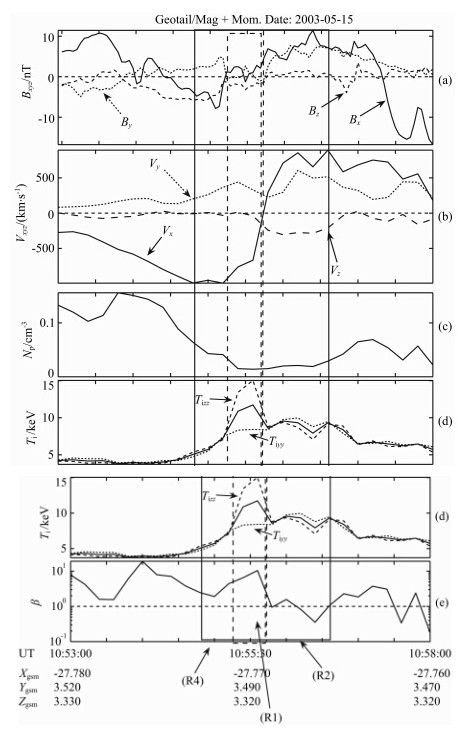
 | 图 1 2003年5月15日磁场重联耗散区穿越过程的事件总体概览.从上到下分别给出GSM坐标系中的磁场三分量、等离子体速度三分量、质子密度、离子温度和等离子体β值Fig. 1 Magnetic reconnection diffusion region crossing by Geotail on May 15,2003. Magnetic field,plasma velocity,proton density,ion temperature, and plasma β are respectively plotted from top to bottom. All data are shown in GSM coordinate |
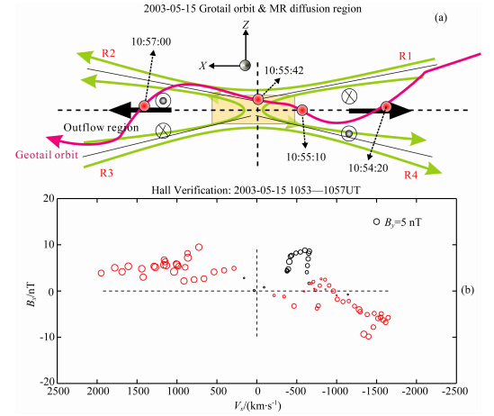
 | 图 2(a)磁场重联耗散区穿越示意图,红色带箭头曲线代表Geotail卫星相对于磁场重联耗散区的轨迹;(b)在磁场重联耗散区内的霍尔磁场特性验证,红色和黑色圆圈分别代表霍尔磁场的方向(红色为正,黑色为负)和大小Fig. 2(a)Illustration of the magnetic reconnection diffusion region crossing by Geotail. The purple arrowed curve represents the orbit of the spacecraft relative to the reconnection diffusion region.(b)Verification of the Hall characteristics of magnetic field(Hall)within the reconnection diffusion region. The red and black circles represent positive and negative Hall,respectively |
Geotail 卫星在2003年5月15日世界时10 ∶ 50 到11 ∶ 00 大约位于[-27.7,3.5,3.3] RE 的近地磁 尾,使用地心-太阳-磁层坐标系(GSM,Geocentric Solar Magnetospheric),图 1给出本次磁场重联事件的概览.图 1a是由MGF仪器(Kokubun et al., 1994)提供的3s精度的磁场数据的三个分量.图 1(b,c,d)是等离子体参数,包括等离子体速度三分量Vx,质子密度Np和离子温度Ti(虚线和点线分别 为卫星坐标系内的Y方向和Z方向的温度Tiyy和Tizz,Ti为根据Tiyy和Tizz计算得到的离子温度),数据均来自 Geotail卫星的LEP仪器(Mukai et al., 1994),精 度为12 s.图 1b表明,在一个很短的时间段10 ∶ 53— 10 ∶ 57 UT内,等离子体流Vx突增至约800~ 1000 km·s-1并且在约10 ∶ 55 ∶ 42 UT时发生由尾向到地向的反向.磁场Bx在这个时间段很小,表明卫星靠近中心电流片.Bx从负到正的变化,说明Geotail卫星在约10 ∶ 55 ∶ 42 UT从中性片的南侧穿越到北侧(图 1用虚竖线标识).等离子体密度(图 1c)在等离子体流Vx反转的同时降低,而离子温度(图 1d)则增高,呈现出密度耗空区的结构,表明卫 星此时在磁场重联X线附近.图 1中的实线框给出 卫星处于非常靠近磁场重联X线的时间段(10 ∶ 54 ∶ 45—10 ∶ 56 ∶ 35 UT),此时,离子体流Vx从负向极大值反转到正向极大值,且磁场z分量Bz从负向到正向改 变.图 1e给出了等离子体β(β=2μ0·nkT/B02)曲线. 点线是β=1的线,而β>1表明卫星位于等离子体片的中心(Asano et al., 2004).Geotail在整个时间段主要位于电流片内.
由上可知,重联耗散区穿越是由Geotail卫星位于中性电流片内时(Bx 极小,同时 β>1)等离子体流由尾向到地向的反流(Vx)以及从-/+的Bz的反向而被辨识的.另外,值得注意的是,位于极光椭圆区中的IMAGE卫星在10 ∶ 57 ∶ 31世界时探测极光亮斑的增强,表明亚暴活动趋强.该亮斑出现的时间基本对应于近地磁尾中的磁场重联充分发展并被Geotail卫星穿越的时间.
霍尔磁场By是无碰撞磁场重联最典型的特征(Ma and Bhattacharjee, 2001; Birn et al., 2001; Nagai et al., 2001,2003).为证实该磁场重联为无碰撞重联,我们在Bx-Vx平面绘出了霍尔磁场By的值(见图 2下半部分),这与Borg 等(2005)的图 3相似.圆圈表示霍尔磁场By,这里By剔除了小导向场〈By〉=0.3 nT.圆圈的半径正比于绝对霍尔磁场B′ y的大小(B′ y=〈By0〉-〈By〉,By0是原始观测值). 圆圈的颜色代表霍尔磁场的方向,即红色和黑色分 别代表B′ y值的正和负.四个子区域(用R1,R2,R3和R4表示)用水平和竖直点线分开,每个子区域代表理想2-D重联耗散区的四个区域.
从图 2b中注意到,在Geotail卫星从X-line的尾向到地向时B′ y的正负没有变化,表明卫星是从R4直接到R2区域的,在两个区域B′ y都是正值.然而,在约图 1虚线方框标出的约30 s的时间段内(从~10 ∶ 55 ∶ 12UT到10 ∶ 55 ∶ 42 UT),我们可以看到Bx>0且Vx<0,而且Bx≈5.8 nT,表明卫星的轨迹仍然覆盖了R1区域,从而使得卫星并没用能够直接穿越尺度很小的电子耗散区,而只是从旁边掠过,总体上处于离子耗散区之内.以上的结果所代表的卫星轨迹的卡通示意图参见图 2a.
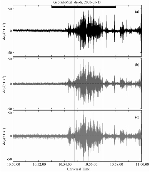
 | 图 3 MGF仪器观测的扰动磁场三分量,数据的时间分辨率为64 HzFig. 3 Magnetic disturb data obtained from MGF instrument,in 64 Hz time resolution |
图 2a的卡通图描述了Geotail卫星穿越磁场重联离子耗散区的过程.粉红色线代表Geotail相对于重联耗散区(X-Z平面)的具体轨迹.电子耗散区在中间,用透明长方形标识.基于上文分析,我们已经有理由相信在卫星穿越离子耗散区的过程中,在10 ∶ 55 ∶ 42 UT时刻前后,卫星处于靠近电子耗散区的离子耗散区内.
Geotail卫星在短时间内观测到磁场重联的霍尔磁场结构,以及伴随等离子体流反向时刻前出现的Bx的反转,表明卫星从尾向—南尾瓣一侧(R4区域)在X线附近经短时的尾向—北尾瓣过渡(R1区域)穿越离子耗散区到地向—北尾瓣一侧(R2区域),这为我们研究磁场重联耗散区内的X线附近核心区域中的等离子体波动提供了很好的机会. 3 在离子耗散区内对低混杂波的观测
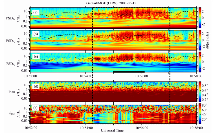
对等离子体波动仪器(PWI)(Matsumoto et al., 1994)数据的分析结果(由于篇幅关系没有显示)表明,在10 ∶ 55 ∶ 42 UT前后当卫星穿越磁场重联耗散区时可以清晰地看到有很强的波动增强.这些增强的波动主要包括两部分,一是高频部分(f>fce),另一个是低频部分(f 图 3给出了从MGF仪器测得的扰动磁场的三分量(dBx,dBy和dBz).图 3a顶部的黑色方条表示出Geotail穿越磁场重联耗散区的时间段,而两条垂直实线标出当等离子体反流且磁场x分量Bx从负到正反转的时间段(10 ∶ 54 ∶ 45—10 ∶ 57 ∶ 00 UT).从图上可见,在Geotail卫星处于磁场重联X线附近的较短时间段内,扰动磁场的三个分量都有强烈的波动特征.我们对扰动磁场进行小波分析,采用“Morlet” 函数为小波分析母函数.分析结果(没有显示)表明,在低混杂频率f<sub>LH(f<sub>LH~6.6 Hz)附近有很强烈的波动增强.频率低于低混杂频率的低频部分的波可能是低混杂波.我们采用奇异值分解(singular value decomposition,SVD)的分析方法(Santolik et al., 2003)对扰动磁场(dBx,dBy,dBz)进行详细分析以确认它为低混杂波. 图 4给出了对磁场进行SVD分析的结果.图 4(a-c)是波动的波谱密度,图 4b显示平面波特征参量planarity,图 4e给出波的传播角度θ(b,k),即波矢与背景磁场的角度,每个子图中画出的黑色虚线代表低混杂频率(f<sub>LH),等离子体反流且磁场x分量Bx很小的时间段(10 ∶ 54 ∶ 45—10 ∶ 56 ∶ 30 UT)用黑色虚线框标识. 从图 4(a-c)可见,扰动磁场的三个分量(dBx,dBy,dBz)在低混杂频率下的波动增强出现在当卫 星穿越磁场重联并处于X线附近的时间段10 ∶ 54 ∶ 20—10 ∶ 57 ∶ 00 UT 上(两条竖直虚线之间).Planarity0表明该波动属于平面波,而θ→90°则表明波动的传播方向是准垂直于背景磁场.在该图可以明显地看到磁场扰动在10 ∶ 54 ∶ 20—10 ∶ 57 ∶ 00 UT时间段内存在峰值频率为低混杂频率的波动增强,且该波动为准垂直于背景磁力线传播的平面波,这是典型的LHW的特征.另外,我们注意到在大于低混杂频率f<sub>LH的频段上,波动不具有平面波的特征(即P~0.4),因此该部分波动不属于低混杂波. 观测和分析表明,在Geotail卫星穿越离子耗散区的整个过程中观测到了强的低混杂波.尤其是在卫星穿越磁场重联耗散区并处于X线附近的时间段10 ∶ 54 ∶ 20—10 ∶ 57 ∶ 00 UT内,低混杂波表现得最强,表明当磁场重联充分发展之后,在核心区域仍然存在增强的低混杂波,说明低混杂波贯穿磁场重联的整个发展过程. 4 结论和讨论 本文主要研究Geotail卫星于2003年5月15日在近地磁尾观测到磁场重联并穿越耗散区时在该磁场重联耗散区内的低混杂波.Geotail卫星在2003年5月15日的磁场重联事件中直接穿越了离子耗 散区并观测到了清晰的霍尔磁场(By).观测证据表 明卫星在短时间内从尾向—南尾瓣一侧(R4区域)在X线附近经短时的尾向—北尾瓣过渡(R1区域)穿越离子耗散区到地向—北尾瓣一侧(R2区域),持续时间大约为2 min.这为我们研究磁场重联耗散区内的X线附近核心区域中的等离子体波动提供了很好的机会. 本文详细研究了离子耗散区内的等离子体波动.结果表明,低混杂波在耗散区内的整个Geotail卫星穿越轨迹上被观测到;低混杂波属于电磁波动.这些观测分析结果基本上与文献中的计算机等离子体模拟结果(Ji et al., 2004)以及Cluster卫星观测的结果(Zhou et al., 2009)相符合. 本文的观测结果与一些计算机数值模拟的结论 有点冲突.Shinohara和Fujimoto(2005)以及Tanaka 等(2005,2006)均开展了二维或者三维的计算机等离子体模拟实验来研究磁场重联过程中的低混杂波,结果表明当磁场重联充分发展之后低混杂波将消失.然而,本文基于Geotail卫星的直接观测结果表明低混杂波能够在磁场重联的整个过程存在,低混杂波在磁场重联充分发展之后仍然相对活跃.观测分析与计算机模拟结果的不一致将可能对计算机模拟进行局部修正提供观测证据的支持. 还应注意到有一小段约5 s的时间(约10 ∶ 55 ∶ 40—10 ∶ 55 ∶ 45 UT)磁场的三个分量的 扰动减弱(图 3),其功率谱密度也很低(图 4).这个时间段对应于反流时刻,此时Geotail卫星正好在磁场重联耗散区的入流区非常靠近X线的位置(参考图 2).这说明,低混杂波是磁场重联诱发的现象,它不存在于入流区.然而,若不考虑这一小段约5 s的时间,本文对波动分析的结果仍说明低混杂波在磁场重联耗散区内非常靠近磁场重联X线的区域内仍然非常强. Wang等(2010)发现Cluster卫星在磁场重联耗散区中也观测到了低混杂频率上的波动,在接近离子耗散区中心观测到的次级磁岛有强大的核心磁场(Wang et al., 2010).Wang 等(2010)报道的低混杂波具有这么一种特征:在次级磁岛的外边缘区 域观测到的低混杂波的强度较强,而在核心区域则很弱.本文的Geotail卫星的观测结果与Cluster 卫星的类似,也可以在离子耗散区的中心区域观测到; 但与之稍微不同的是,在靠近磁场重联X线的核 心区域,如图 1和图 4所见,卫星在10 ∶ 55 ∶ 42—10 ∶ 55 ∶ 45 UT观测到等离子体流反流的同时磁场Bx出现反转的时间段内,除去当卫星处于入流区(~10 ∶ 55 ∶ 40—10 ∶ 55 ∶ 45 UT)这短短几秒时间,低混杂波仍然非常强. 此外,本文在磁场重联耗散区内X线区域附近观测到低混杂波,这并未排除在同一区域有其他波动模式的存在.从图 4可以看到,其他电磁波动模式也可以被观测到,例如,高于低混杂频率f<sub>LH的频段上有准平行传播角(图 4e蓝色部分,θ<45°)可能是哨声波(Deng and Matsumoto, 2001; Wei et al., 2007).从图 4还可以看到在低于低混杂频率f<sub>LH的频段上有准平行传播角的波动模式,在今后的工作中我们将对这些波动进行详细分析. 本文的观测对低混杂波在磁场重联中的具体表现提供了新的观测证据并有可能修正前人的理论.我们对磁场重联耗散区中的低混杂波的激发机制的认识仍然比较模糊,但超出了本文的研究范围.我们将在以后的工作中利用粒子模拟来研究其激发机制.
图 4 2003年5月15日磁场重联耗散区穿越过程中MGF仪器观测的扰动磁场的SVD分析结果.(a—c)功率谱密度;(d)波动的平面度;(e)波动的传播角θ(k,b).每一个面板上的黑色虚线代表低混杂频率,此处,f<sub>LH≈6.6 HzFig. 4 “SVD” analysis on the magnetic disturbed data obtained from MGF instrument for the magnetic reconnection diffusion region crossing on May 15,2003.(a—c)Power spectrogram density of three magnetic field components.(d)Planarity for the wave.(e)Propagation angle of the waves,θ(k,b). The dashed black line in each panel is the plot of the lower hybrid frequency,f<sub>LH≈6.6 Hz
| [1] | "Asano Y, Mukai T, Hoshino M, et al. 2004. Current sheet structure around the near-Earth neutral line observed by Geotail. J. Geophys. Res., 109: A02212, doi: 10.1029/2003JA010114. |
| [2] | Bale S D, Mozer F S, Phan T. 2002. Observation of lower hybrid drift instability in the diffusion region at a reconnecting magnetopause. Geophys. Res. Lett., 29(24): 33-1-33-4. |
| [3] | Birn J, Drake J F, Shay M A, et al. 2001. Geospace Environmental Modeling (GEM) magnetic reconnection challenge. J. Geophys. Res., 106(A3): 3715-3719. |
| [4] | Birn J, Hesse M. 2001. Geospace Environment Modeling (GEM) magnetic reconnection challenge: Resistive tearing, anisotropic pressure and Hall effects. J. Geophys. Res., 106(A3): 3737-3750. |
| [5] | Borg A L, Øieroset M, Phan T D, et al. 2005. Cluster encounter of a magnetic reconnection diffusion region in the near-Earth magnetotail on September 19, 2003. Geophys. Res. Lett., 32: L19105, doi: 10.1029/2005GL023794. |
| [6] | Cattell C, Dombeck J, Wygant J, et al. 2005. Cluster observations of electron holes in association with magnetotail reconnection and comparison to simulations. J. Geophys. Res., 110: A01211, doi: 10.1029/2004JA010519. |
| [7] | Daughton W. 2003. Electromagnetic properties of the lower-hybrid drift instability in a thin current sheet. Phys. Plasmas, 10: 3103. |
| [8] | Davidson R C, Gladd N T, Wu C S, et al. 1977. Effects of finite plasma beta on the lower-hybrid-drift-instability. Phys. Fluids., 20, 301, doi: 10.1063/1.861867. |
| [9] | Deng X H, Matsumoto H. 2001. Rapid magnetic reconnection in the Earth’s magnetosphere mediated by whistler waves. Nature, 410(6828): 557-560. |
| [10] | Deng X H, Matsumoto H, Kojima H, et al. 2004. Geotail encounter with reconnection diffusion region in the Earth's magnetotail: Evidence of multiple X lines collisionless reconnection? J. Geophys. Res., 109, A05206, doi: 10.1029/2003JA010031. |
| [11] | Deng X H, Zhou M, Li S Y, et al. 2009. Dynamics and waves near multiple magnetic null points in reconnection diffusion region. J. Geophys. Res., 114, A07216, doi: 10.1029/2008JA013197. |
| [12] | Fujimoto M, Shinohara I, Kojima H. 2011. Reconnection and waves: A review with a perspective. Space Sci. Rev., 160(1-4): 123-143, doi: 10.1007/s11214-011-9807-7. |
| [13] | Ji H, Terry S, Yamada M, et al. 2004. Electromagnetic fluctuations during fast reconnection in a laboratory plasma. Phys. Rev. Lett., 92, 115001, doi: 10.2172/811969. |
| [14] | Kokubun S, Yamamoto T, Acuna M H, et al. 1994. The geotail magnetic field experiment. Journal of Geomagnetism and Geoelectricity, 46(1): 7-21. |
| [15] | Li S Y, Deng X H, Zhou M, et al. 2009. Statistical study of electrostatic solitary waves associated with reconnection: Geotail observations. Adv. Space Res., 43(3): 394-400, doi: 10.1016/j.asr.2008.05.013. |
| [16] | Li S Y, Zhang S F, Cai H, et al. 2013. Statistics of the tri-polar electrostatic solitary waves within magnetic reconnection diffusion region in the near-Earth magnetotail. J. Geophys. Res. Space Physics., 118(6): 2911-2918, doi: 10.1002/jgra.50209. |
| [17] | Li S Y, Omura Y, Lembège B, et al. 2014. Geotail observation of counter directed ESWs associated with the separatrix of magnetic reconnection in the near-Earth magnetotail. J. Geophys. Res.: Space Physics, 119(1): 202-210, doi: 10.1002/2013JA018920. |
| [18] | Matsumoto H, Nagano I, Anderson R R, et al. 1994. Plasma wave observations with Geotail Spacecraft. Journal of Geomagnetism and Geoelectricity, 46(1): 59-95. |
| [19] | Mandt M E, Denton R E, Drake J F. 1994. Transition to whistler mediated magnetic reconnection. Geophys. Res. Lett., 21(1): 73-76. |
| [20] | Ma Z W, Bhattacharjee A. 2001. Hall magnetohydrodynamic reconnection: The Geospace Environment Modeling challenge. J. Geophys. Res., 106(A3): 3773-3782, doi: 10.1029/1999JA001004. |
| [21] | Mukai T, Machida S, Saito Y, et al. 1994. The low energy particle (LEP) experiment onboard the Geotail satellite. Journal of Geomagnetism and Geoelectricity, 46(8): 669-692. |
| [22] | Nagai T, Shinohara I, Fujimoto M, et al. 2001. Geotail observations of the Hall current system: Evidence of magnetic reconnection in the magnetotail. J. Geophys. Res., 106(A11): 25929-25949. |
| [23] | Nagai T, Shinohara I, Fujimoto M, et al. 2003. Structure of the hall current system in the vicinity of the magnetic reconnection site. J. Geophys. Res., 108(A10): 1357, doi: 10.1029/2003JA009900. |
| [24] | Nagai T, Shinohara I, Fujimoto M, et al. 2011. Construction of magnetic reconnection in the near-Earth magnetotail with Geotail. J. Geophys. Res., 116: A04222, doi: 10.1029/2010JA016283. |
| [25] | Rogers B N, Denton R E, Drake J F, et al. 2001. Role of dispersive waves in collisionless magnetic reconnection. Phys. Rev. Lett., 87: 195004, doi: 10.1103/PhysRevLett.87.195004. |
| [26] | Santolik O, Parrot M, Lefeuvre F. 2003. Singular value decomposition methods for wave propagation analysis. Radio Sci., 381: 1010, doi: 10.1029/2000RS002523. |
| [27] | Shay M A, Drake J F, Rogers B N, et al. 1999. The scaling of collisionless magnetic reconnection for large systems. Geophys. Res. Lett., 26(14): 2163-2166. |
| [28] | Shay M A, Drake J F, Rogers B N, et al. 2001. Alfvénic collisionless magnetic reconnection and the Hall term. J. Geophys. Res., 106(A3): 3759-3772. |
| [29] | Shinohara I, Nagai T, Fujimoto M, et al. 1998. Low-frequency electromagnetic turbulence observed near the substorm onset site. J. Geophys. Res., 103(A9): 20365-20388. |
| [30] | Shinohara I, Suzuki H, Fujimoto M, et al. 2001. Rapid Large-Scale Magnetic-Field dissipation in a collisionless current sheet via coupling between Kelvin-Helmholtz and Lower-Hybrid drift instabilities. Phys. Rev. Lett., 87(9): 095001, doi: 10.1103/ PhysRevLett.87.095001. |
| [31] | Shinohara I, Fujimoto M. 2005. Formation of thin electron current layer associated with lower hybrid drift instability and its relation to quick reconnection triggering. // Hoshino M, Omura Y, Lanzerotti L. Frontiers of Magnetospheric Plasma Physics. COSPAR Colloq. Ser., 2005, vol. 16.New York: Elsevier, 123-129. |
| [32] | Tanaka K G, Shinohara I, Fujimoto M. 2005. Quick magnetic reconnection triggering in an ion-scale current sheet: Transition from Type-I to Type-II. Geophys. Res. Lett., 32: L17106, doi: 10.1029/2005GL023718. |
| [33] | Tanaka K G, Shinohara I, Fujimoto M. 2006. Parameter dependence of quick magnetic reconnection triggering: A survey study using two-dimensional simulations. J. Geophys. Res., 111: A11S18, doi: 10.1029/2006JA011968. |
| [34] | Vaivads A, Andre M, Buchert S C, et al. 2004. Cluster observations of lower hybrid turbulence within thin layers at the magnetopause. Geophys. Res. Lett., 31: 3804, doi: 10.1029/2003GL018142. |
| [35] | Wang R S, Lu Q M, Li X, et al. 2010. Observations of energetic electrons up to 200 keV associated with a secondary island near the center of an ion diffusion region: A cluster case study. J. Geophys. Res., 115: A11201, doi: 10.1029/2010JA015473. |
| [36] | Xiao C J, Wang X G, Pu Z Y, et al. 2007. Satellite observations of separator-line geometry of three-dimensional magnetic reconnection. Nature Phys., 3(9): 609-613, doi: 10.1038/nphys650. |
| [37] | Zenitani S, Shinohara I, Nagai T. 2012. Evidence for the dissipation region in magnetotail reconnection. Geophys. Res. Lett., 39, doi: 10.1029/2012GL051938. |
| [38] | Zhou M, Deng X H, Li S Y, et al. 2009. Observation of waves near lower hybrid frequency in the reconnection region with thin current sheet. J. Geophys. Res., 114, A02216, doi: 10.1029/2008JA013427. |
 2014, Vol. 57

