2. State Key Laboratory of Smart Grid Protection and Control, Nanjing 211106, China;
3. College of Energy and Electrical Engineering Hohai University, Nanjing 210098, China;
4. State Grid Shanghai Municiple Electric Power Company, Shanghai 200122, China
HTS (High temperature superconducting) cable has the characteristics of high power transmission, low line loss, less environmental pollution, compact structure, etc. Under transmission of the same electric energy, HTS cable can reduce the voltage level by 1–2, which is suitable for use in rapidly developing big cities and high-density urban areas [1]. The world's first set of grid-connected high temperature superconducting cables are 30 m/three-phase/30 kV/1250A high-temperature superconducting cables developed by Southwire Company of U.S.A., which were connected to the grid at the end of 1999 [2]; on July 10, 2004, the first set of high temperature superconducting cable system of China was put into operation in Phuket Substation in Kunming of Yunnan Province. The length of the superconducting cable body is 33.5 m, and the protection is equipped with a three-layer over-current protection scheme based on different current levels [3]. With the development of the manufacturing technology of high temperature superconducting cables in China, now the construction of kilometer-level high temperature superconducting cable demonstration project has been started. In the future, the long distance transmission of electricity may be realized through superconducting cables. Therefore, it is necessary to study the relay protection configuration scheme for long distance superconducting lines.
In electrical characteristics, the superconducting cables differ greatly from the conventional cable lines. The resistance of the superconducting cable is related to the current density. When the current density is less than the critical current density, the resistance of the superconducting cable is almost zero. When the current density is larger than the critical current density, the resistance of the superconducting cable will increase. Meanwhile, the resistance of the superconducting cable is also related to temperature. If the temperature is lower than the critical temperature, it is in the superconducting state; if the temperature is greater than the critical temperature, it is in the quench state. In addition, as the distributed capacitance of the superconducting cable is larger, there are some challenges along the way of application of the existing low-voltage line protection principle in the superconducting line.
For differential protection, as the distributed capacitance of the superconducting cable is larger than that of the conventional cable, it is necessary to consider whether the distributed capacitance of the kilometer-level superconducting cable will affect the differential protection functions.
For distance protection, as the transmission capacity increases, the short-circuit impedance becomes smaller and smaller. In case of short circuits, the short circuit fault current will be generally larger than the critical current transmitted by the superconducting cable, and the resistance of the superconducting cable will increases rapidly with the increase of the fault current. Moreover, the impedance of the kilometer-level superconducting cable is smaller, so the distance protection is no longer applicable.
For conventional cables and superconducting cables, the setting idea of over-current backup protection is not completely consistent. The cooperation between upper and lower levels is considered in over-current protection setting of conventional cables, without failure to operation or incorrect operation. While for superconducting cables, in case of over current, the faults are removed before the temperature reaches the upper temperature limit allowed by the superconducting cable, so as to ensure there will be no irreparable damage to the performance of the superconducting cable. There are some troubles in the setting.
For quench protection, it is mainly to install a sensor on the superconducting cable body to monitor the non-electric quantity information of the conductor such as temperature and pressure, etc. For the kilometer-level superconducting line, only the terminals on both sides are convenient for installation and information collection, which has some limitations on the fast reflection of quench of the superconducting cable on the whole.
In view of the characteristics of the superconducting line, this paper puts forward a practical protection configuration scheme, and combined with the actual situation of the kilometer-level superconducting line of Shanghai, presents a scheme for tripping and closing of the superconducting line.
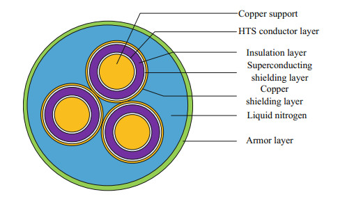
2 Analysis of Characteristics of the Superconducting CableThe electrical parameters of HTS cables depend on the materials and geometric sizes used in the superconducting cable. Figure 1 shows the typical structure drawing of the three-phase belted-type superconducting cable, respectively copper support, HTS conductor layer, insulation layer, superconducting shielding layer, copper shielding layer, liquid nitrogen layer and armor layer from inside to outside. Compared with conventional power cables of the same voltage level, the electrical parameters of HTS cables have the following characteristics: the resistance of HTS cables is basically zero when it is in the superconducting state, and the reactance of HTS cables is larger than that of the conventional cables. This is because the inductive impedance approximation is proportional to the logarithm of the distance between three phases. However, the phase-to-phase spacing of high-temperature cables is larger than that of the conventional cables, and the capacitance of HTS cables is larger than that of the conventional cables. This is because the thicknesses of insulation layers of both are basically the same, and the cooling channel in the superconducting cable leads to the increase of the equivalent radius of the conductor wire core, so the capacitance increases.
|
Fig.1 Typical structure diagram of three-phase superconducting cable |
3 Introduction of the Kilometer-Level Superconducting Cable Demonstration Project 3.1 Brief Introduction of the Demonstration Project
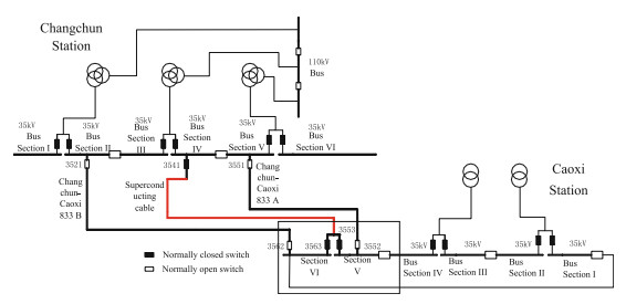
The line from Changchun Station to Caoxi Station is selected as the demonstration application scene for the kilometer-level superconducting line in Shanghai. The primary system chart is shown in Fig. 2. Based on the advantages of small size, light weight, low loss and large transmission capacity of the superconducting cable, this paper attempts to substitute the superconducting cable for transmission of power distribution network lines. One circuit of 35 kV superconducting cables is newly built from 220 kV Changchun Station to 220 kV Caoxi Station. 30 chambers are stored in 35 kV bus section Ⅳ in Changchun Station for use by Caoxi Station. 30 chambers are reserved in 35 kV bus section Ⅴ and 37 chambers are reserved in 35 kV bus section Ⅵ. The original two circuits of Changchun-Caoxi 833 Line A and Changchun-Caoxi 833 Line B from Changchun Station to Caoxi Station are changed to backup lines. This method is similar to the current grid structure in Shanghai without major changes. Meanwhile, on the premise of ensuring the reliability of power supply, it is convenient for long-term operation, maintenance and dispatching.
|
Fig.2 Wiring diagram of kilometer-level superconducting cable demonstration project |
3.2 System Structure of the Superconducting Cable in the Demonstration Project
The kilometer-level superconducting cable system mainly consists of the superconducting cable body, intermediate joint, terminal and cooling system, with the structure shown in Fig. 3.

|
Fig.3 Diagram of system structure of kilometer-level superconducting cable |
The superconducting cable adopts the three-phase belted-type cold insulation method. With compact structure, small transmission loss and low stray magnetic field, its superconducting current-carrying layer, high-voltage insulation layer and superconducting shielding layer are all in the liquid nitrogen temperature region. The superconducting wires are wound in layers around the supporting framework. The distribution of conductors and the winding pitch will directly affect the current division between layers and the size of AC (alternating current) loss; the coaxial double-layer bellows forms a forced flow cooling channel, and the inside of the bellows should keep high vacuum and be embedded with the multiple-layer radiation protection screen, so as to enable the cable core to be thermally insulated from the external environment and ensure a low temperature environment required for cable operation.
As the head end of the cable, the cable terminal is the connection channel between the superconducting cable and the external electrical equipment as well as between the cooling medium and the refrigeration equipment. It is responsible for the transition between temperature and potential. In order to ensure the connection between cable core and conventional conductor at low resistance, maintain good electrical insulation between phases and ground, and bear the temperature gradient of the system and the surrounding environment to achieve vacuum isolation, in addition to the electrical connection and insulation performance, the inhibition of heat leakage should be considered in the design and manufacturing of terminals.
The intermediate joints are used to connect cables of the kilometer-level superconducting line so as to achieve long-distance power transmission. As the connecting channel between the superconducting cable cooling medium and the refrigeration equipment, the joint is also responsible for the transition between temperature and potential. It is required to not only ensure the connection between cable cores at low resistance and maintain good electrical insulation between phases and ground, but also bear the temperature gradient of the system and the surrounding environment so as to achieve vacuum isolation.
The cooling system is consisted of the refrigerator, liquid nitrogen pump, super-cooled box, storage tank, circulation circuit, standby set, etc. The basic cooling principle of the cable is to use the sensible heat of the super-cooled liquid nitrogen to bring the thermal load produced in the operation process to the cooling device, and then send the super-cooled liquid nitrogen to the cooling channel of the cable after being cooled by the refrigerator, forming a closed circuit, so as to keep the superconducting transmission line an appropriate operation temperature, liquid nitrogen coolant pressure and flow rate.
4 Protection Scheme for Kilometer-Level Superconducting LinesThe HTS cable usually has a high power transmission. In the event of power system faults, late removal of the fault will cause serious damage to the superconducting cable body and may endanger the stability of the entire power system. Therefore, the kilometer-level superconducting line is necessary to be equipped with the whole-line quick-action protection of differential protection and quench protection as the main protection. The over-current protection should be equipped as the backup protection.
For the cable transmission line, the fault is usually permanent, and there are backup lines for the superconducting cables in this demonstration project. Section 5 describes the auto-switching logic of backup lines in case that the superconducting line malfunctions. The continuity and reliability of power supply can be ensured, so the reclosure is not necessary. The breaker failure protection can be equipped to ensure the reliable isolation of faults in case that the superconducting cable malfunctions and the breaker fails.
4.1 Differential ProtectionThe differential protection has natural selectivity towardsinternal and externalfaults and can remove the internal faults quickly, the advantage of the differential protection as the main protection of the superconducting cable is obvious. The factors affecting the performance of the differential protection action mainly include the following 5 aspects [4]. The first is the error and unbalanced current of the current transformer; the second is the capacitance current of the transmission line; the third is the saturation of the current transformer; the fourth is the disconnection of the secondary circuit of the current transformer; the fifth is the reliability of the fiber channel. Except for the second one, there is no difference for other factors between the superconducting line and the conventional cable line. And all can be solved by the differential protection through fixed value setting and algorithm. Therefore, it is only necessary to consider whether the kilometer-level superconducting line is affected by the capacitance current.
The neutral ungrounded operation mode is mostly adopted in China's medium-voltage distribution network. With the expansion of the urban power grid and the increase of cable lines, the grounding current of the distribution network increases day by day. The regulations stipulate that when the 10 and 35 kV grid capacitive current is greater than 20 and 10 A respectively, the arcing coil should be installed to compensate the capacitive current [5]. The ability to accurately measure the capacitance current of distribution network determines whether arc suppression coil is needed and the ability to accurately compensate arc suppression coil. It is an important subject to study the measurement method of capacitive current in distribution network for small current grounding system [6-8]. When a superconducting line is used in a low-current grounding system, if the capacitance current is large, it will be compensated by the arc suppression coil. After compensation, the grounding arc should be automatically extinguished. When superconducting cables are used in grounding systems, The method of capacitance current compensation should be studied.
The capacitance current compensation method based on time domain can compensate the capacitance current at various frequencies and has good compensation effect for both steady and transient capacitance current.
For the capacitance current compensation method based on time domain, the relation between capacitance current and voltage is:
| $ {i_c} = C\frac{{du}}{{dt}} $ | (1) |
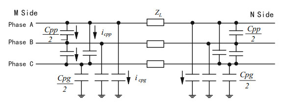
Figure 4 is a three-phase cable line Π-type equivalent circuit.
|
Fig.4 Superconducting cable line Π-type equivalent circuit |
The current of phase A on both sides of the cable can be obtained according to Eq. (1):
| $ \left\{ {\begin{array}{*{20}{c}} {ic_m^a = \frac{{{C_{pg}}}}{2} \cdot \frac{{du_m^a}}{{dt}} + \frac{{{C_{pp}}}}{2} \cdot \frac{{du_m^{ab}}}{{dt}} + \frac{{{C_{pg}}}}{2} \cdot \frac{{du_m^{ac}}}{{dt}}}\\ {ic_n^a = \frac{{{C_{pg}}}}{2} \cdot \frac{{du_n^a}}{{dt}} + \frac{{{C_{pp}}}}{2} \cdot \frac{{du_n^{ab}}}{{dt}} + \frac{{{C_{pg}}}}{2} \cdot \frac{{du_n^{ac}}}{{dt}}} \end{array}} \right. $ | (2) |
where, Cpg is the phase to ground capacitance of the superconducting cable, Cpp is the phase to phase capacitance, which is related to the positive sequence and zero sequence capacitance of the line as follows:
| $ \left\{ {\begin{array}{*{20}{c}} {{C_{pg}} = {C_0}\;\;\;\;\;\;\;}\\ {{C_{pp}} = \frac{{{C_1} - {C_0}}}{3}} \end{array}} \right. $ | (3) |
The phase voltage is collected by the protection device, the equation can be known by the approximate derivation of discrete sampling points:
| $ \frac{{du\left( t \right)}}{{dt}} = \frac{{u\left( {t + \Delta t} \right) - u\left( {t - \Delta t} \right)}}{{2\Delta t}} $ | (4) |
Using formula (4), icma(t), icna(t) can be obtained by formula (2), and then phase A compensation currents of both sides are:
| $ \left\{ {\begin{array}{*{20}{c}} {i_m^a\left( t \right) = i\left( t \right) - ic_m^a\left( t \right)}\\ {i_n^a\left( t \right) = i\left( t \right) - ic_n^a\left( t \right)} \end{array}} \right. $ | (5) |
Based on the calculation of parameters of the cold insulation three-phase belted-type superconducting cable in this demonstration project, the comparison with the parameters of the conventional cable is shown in the Table 1.
| Table 1 Comparison of the parameters between superconducting cable and conventional cable |
The superconducting cable line model was established to verify the compensation effect of capacitance current only, and the temperature rise caused by the increase of superconducting cable current was not considered in the modeling.
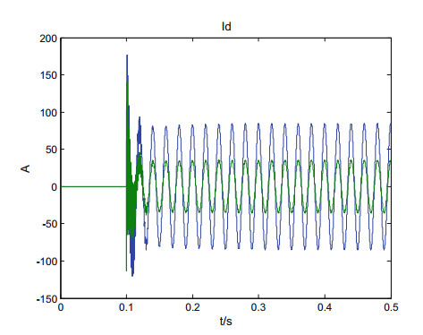
Because of the space limitation, only the switching on simulation results are listed.
In the Fig. 5, the blue waveform is the differential current before compensation and the green one is after compensation. It can be seen from the figure that the capacitance current compensation method based on time domain has a certain compensation effect on the capacitance current of the superconducting cable.
|
Fig.5 The waveforms of before and after compensation when switching on |
Therefore, if the voltage level of the superconducting cable is high and the cable length is long, the capacitance current should still be considered. The capacitance current compensation mechanism should be adopted for differential protection to improve the sensitivity of differential protection.
For the demonstration project of km-class superconducting cable, although the capacitance per kilometer of the superconducting cable is higher than that of the conventional cable, due to low voltage level and short line, the calculated capacitance current is still low The primary value of the steady-state capacitive current is about 1.7 A, the CT variable-ratio is 1250/5, and the secondary value is about 0.0068 A. Although the transient capacitive current of the line generated by out-of-area faults and empty charging of the line may reach several times of the steady-state current [9], the value is still very small. The line differential protection used in this demonstration project does not need to consider capacitor current compensation. The differential threshold value is set according to the unbalance current (CT measuring error, capacitance current) of the dodging system, and the sensitivity is ≥ 2.
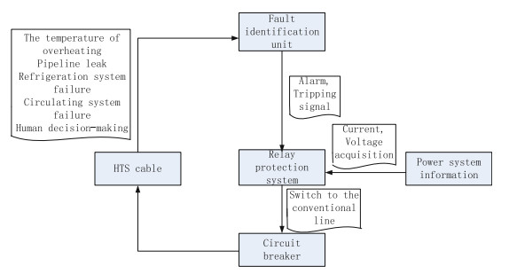
4.2 Quench ProtectionWhen the superconductor runs into the superconducting state, there are three critical values: critical temperature Tc, critical field Hc and critical current Ic. The research shows that when any of the above three basic parameters of the superconductor exceeds its critical value in the process of operation, the superconductivity of the superconductor will disappear and part of it will enter the "normal state". At present, the quench detection of the superconductor at home and abroad is all based on these three basic parameters. The main factors affecting these three parameters are faults of the cooling system, internal faults of the superconducting cable, short circuit faults, etc. As the temperature, liquid nitrogen pressure and liquid nitrogen flow of the superconducting cable can directly reflect the state of the superconducting cable, the conventional quench protection generally consists of the monitoring and judgment of the above non-electric quantity. An independent fault identification unit is set up to receive the non-electric quantity information collected by the sensor of the superconducting cable in real time, analyze the dynamic characteristics in real time, identify the fault and send the fault signal to the relay system through the preset program. The fault identification unit can be thought of as an independent IED, plugged into a process-layer GOOSE network, and implemented as an information interaction with line protection via GOOSE, or passed directly to the protection via cable wiring. The quench protection system diagram is shown in Fig. 6.
|
Fig.6 Quench protection system diagram |
The general quench detection methods include temperature rise detection, pressure measurement, flow rate detection, ultrasonic detection, voltage detection, etc. [10]. Considering the sensor installation technology and the requirements on heat leakage of cable system, the sensor is actually suitable to be installed only at the port of the superconducting line to monitor the temperature, pressure and flow rate, etc. at the port. When the port data such as temperature, pressure, flow rate, etc. is found to be abnormal, the quench alarm will be raised by fault identification unit, if serious, the quench tripping signal may be sent for tripping both this side and the other side by the protective device (Fig. 7).

|
Fig.7 Diagram of transmission circuit of non-electric quantity signals |
5 Discussion on New-Type Protection Function 5.1 Information Collection Method Based on Wireless Communication Technology
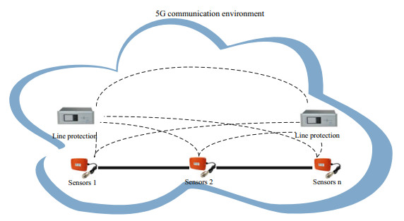
Based on the current manufacturing technology of the superconducting cable, the installation environment on the site as well as the installation technology, the long-distance superconducting cable can be constructed in sections (the length of each section should not be too long) by the method of tap connection. This method provides a condition for tapped installation of the sensor. All the sensors on the superconducting cable serve as collection terminals to monitor the temperature, pressure, liquid nitrogen flow rate, etc. of the superconducting cable in real time and upload the information to the protection device or monitoring system so as to realize the overall information collection of the superconducting cable, condition monitoring and protection of feedback control system. In the traditional method, the sensor needs to send the data to the monitoring device, which uploads the data by means of communication. This kind of method can be easily realized in the substation, but is difficult to be implemented at the tapping point. The development of 5G wireless communication technology provides a technical basis for the construction of ubiquitous Internet of things, enabling the power equipment and information collection platform to be connected to all terminals to collect information in an all-around, multi-dimensional and faster manner [11], and achieving a more perfect protection and control scheme. As the super-high frequency band is applied in 5G technology, the data transmission speed can reach 1 Gbp per second, the transmission distance can also reach 2 km, and the data transmission delay can reach below 1 ms [12]. These key indicators make the application of 5G technology in short line protection possible. As important power equipment for power transmission and distribution network of the power system, the superconducting cable may, based on 5G wireless communication technology, realize the data interaction between the line protection devices on both sides as well as the information interaction between the device and the sensor. Within the kilometer-level scope, it can be exempted from the limitation of tap installation locations. The protection device will build a new-type quench protection based on all data collected from the sensors of the whole line (Fig. 8).
|
Fig.8 Diagram of information collection of wireless communication technology |
6 Tripping and Closing Logic of the Superconducting Cable
There are two backup lines (old lines) for the superconducting cables in this demonstration project. The backup lines are put into service before the superconducting cable is out of service due to internal fault, cooling system fault, cable body fault, etc. to ensure uninterrupted power supply. This section discusses the auto-switching function of incoming line and the tripping logic in case of breaker failure.
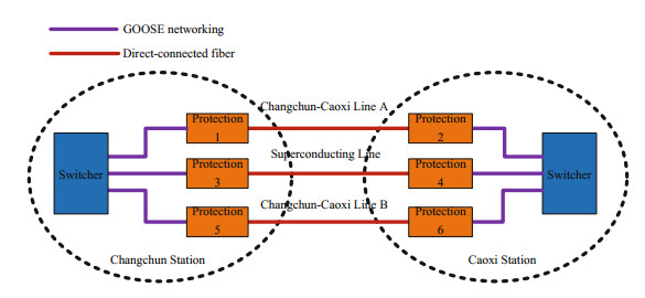
6.1 Configuration of Protection DeviceAs shown in Fig. 2, the 35 kV bus section Ⅳ of Changchun Station passes through the superconducting cable zone to be connected with two buses of Caoxi Station, respectively 35 kV bus section Ⅴ and Ⅵ. As the power restoration time for faults of the superconducting cable is longer than that of the conventional cable, Changchun-Caoxi Line A and Changchun-Caoxi Line B are set for the purpose of ensuring the reliability of power supply. In the event of a failure of the superconducting cable, the power can be supplied from these two conventional cable lines to ensure the continuity of power supply. Changchun-Caoxi Line A, Changchun-Caoxi Line B and the superconducting cable are respectively equipped with a set of optical fiber longitudinal differential protection, with the configuration shown in Fig. 9. The line protection of the three lines forms an overall protection through the GOOSE networks and direct-connected channels on both stations. Logically, the cooperation between each other can be easily realized.
|
Fig.9 Diagram of protection configuration for superconducting and backup lines |
6.2 Tripping and Closing and Failure Logics of the Superconducting Cable
Under normal conditions, the bus section Ⅴ and bus section Ⅵ of Caoxi Station are powered by the superconducting line, Switch 3551 and Switch 3521 are in the closed position, and Changchun-Caoxi 833 Line A and Changchun-Caoxi 833 Line B are in the hot-standby state. In general, there are two types of faults in the superconductor: one is internal fault, which is removed by differential protection action trip; the other is quench of superconductor, which is removed by quench protection trip. The tripping logic of the line protection for the superconducting cable is: switches 3562 and 3552 are closed and switches 3541, 3553 and 3563 are tripped; the specific process is that after fault trip inside the superconducting line area or receipt of the quench signal, the protection 4 sends the GOOSE closing signal, and protection 2 and 6 subscribe to the GOOSE closing signal of protection 4; the switches are closed respectively after each has judged that there is voltage on the line, thus the input of the backup line of the superconducting cable can be completed. Protection 4 subscribes to the position signals of protection 2 and protection 6. After the two lines are confirmed to have been put in, tripping of the breakers and remote tripping of protection 3 are started to complete the tripping logic. The tripping logic of the superconducting line is shown in Fig. 10. If protection 2 or protection 6 judges that there is voltage on the line, but it is not satisfied, or protection 4 fails to receive the closing position signals from the two lines after the closing commander has been sent, it means that the closing is not successful and the closing failure should be reported after short-time delay. The failure of the closing will not affect the tripping logics of protection 3 and protection 4.

|
Fig.10 Tripping logic of superconducting cable |
If there are faults inside the superconducting line area, the late removal of the faults may cause the superconductor to be damaged, resulting in larger loss and failing to be reactivated within a short time. Therefore, the breaker failure protection of the superconducting line should be considered. The interval protection between adjacent breakers (line protection or bus section protection) should subscribe to the tripping signal of the superconducting line, judge the breaker failure based on its own current and trip off the adjacent superconducting breakers through short time delay, so as to realize the failure isolation.
The closing logic of the superconducting cable is: switches 3541, 3553 and 3563 are closed and switches 3521, 3562, 3551 and 3552 are tripped.
The tripping and closing exit of the superconducting line is realized by the line protection through the GOOSE network of the process level in the station and the remote tripping of differential protection at the opposite side. The tripping and closing time of GOOSE is less than 10 ms. The pilot channel delay is less than 5 ms, the opening time of 35 kV breaker takes 30 ms, and as shown in Fig. 11, the overall tripping time of the superconducting line is less than 80 ms.

|
Fig.11 Tripping time of superconducting cable |
7 Conclusion
This paper introduces the wiring forms of the kilometer-level superconducting cable demonstration project, puts forward a whole set of protection configuration scheme taking differential and quench protection as the main protection, presents an auto-switching scheme for introduction of the superconducting line which is not based on the backup auto-switching, and considers the breaker failure of the superconducting line. It provides useful reference value for the protection device configuration of the kilometer-level superconducting cable demonstration project. The practicability of it remains to be further verified in actual projects. As for the superconducting cable, the primary equipment of power system which requires high protection reliability, this paper puts forwards an information collection method based on 5G communication, which needs to be improved and studied in the future.
Acknowledgements Scientific Research Project of the State Grid Corporation of China "Key Technology and Demonstration Application Research of Domestic Kilometer-level High Temperature Superconducting Cable System" (SGSHDK00SPJS1800272).
| 1. |
Qiu M (2017) Applications of superconducting power transmission in power grid. Adv Technol Electr Eng Energy
36(10): 55-62. DOI:10.12067/ateee1707030 (  0) 0) |
| 2. |
Wei D, Zong X, et al (2015) Demonstration project of 35 kV 2000 a cold dielectric high temperature superconductive power cable system. Electr Wire & Cable
2(1): 1-5. (  0) 0) |
| 3. |
Yang J, Zhang Z, Tang Y, et al (2005) Development of HTS cable's monitoring and protection device. Autom Electr Power Syst
29(7): 101-104. (  0) 0) |
| 4. |
Jiali HE (2006) Power system relay protection principle and practical technology.
China Electric Power Press, Beijing.
(  0) 0) |
| 5. |
Zeng X, Yi W, Liu Z, et al (2008) A novel technique of capactive current resonance measurement with signal injected for distribution networks. Autom Electr Power Syst
32(4): 77-80. (  0) 0) |
| 6. |
Zhou Q, Zhang X, Zhang K, et al (2017) Formula erratum for non-power frequency method in power industry standard and new measuring method of capacitive current. Autom Electr Power Syst
41(1): 161-167. DOI:10.7500/aeps20160307013 (  0) 0) |
| 7. |
Chen R, Zhou F, Weng H, et al (2017) Active arc-suppression method based on double closed —loop control under single-phase grounding faults in distribution networks. Autom Electr Power Syst
41(5): 128-133. DOI:10.7500/AEPS20160418003 (  0) 0) |
| 8. |
He L, Ge L, Sun J (2018) Capacitive current measuring method for distribution networks based on resonant frequency prediction model. Autom Electr Power Syst
42(2): 143-147. DOI:10.7500/aeps20170802010 (  0) 0) |
| 9. |
National Electric Power Dispatching and Communication Center (2009) State grid relay protection training materials.
China Electric Power Press, Beijing.
(  0) 0) |
| 10. |
Yu X, Li J, Tang Y (2003) The basic study for Q uench detection in superconducting electric equipments. Eng Sci
5(10): 73-77. (  0) 0) |
| 11. |
Yang X (2019) The construction of the ubiquitous power Internet of things can meet more individual needs. State grid report
(1). (  0) 0) |
| 12. |
Sun Z (2019) Internet of things technology supported by 5G mobile communication. Electron Technol Softw Eng
5: 26. (  0) 0) |
 2020 : 415-430 DOI: 10.1007/978-981-13-9783-7_33


