2. Huazhong Electric Power Dispatch & Communication Bureau, Hubei 430077, China;
3. State Grid Corporation of China, Beijing 100031, China;
4. North China Electrical Power University, Beijing 102206, China;
5. East China Branch of State Grid Corporation, Shanghai 200120, China
In recent years, with the popularization and application of large-capacity and long-distance UHVDC (Ultra high voltage direct current) transmission technology [1, 2], the problem of insufficient dynamic reactive power reserve and voltage support of UHVDC sending and receiving end is increasingly prominent [3, 4]. The new generation of large-capacity synchronous condenser is mainly used in the sending and receiving converter stations of UHVDC projects to improve system stability. Compared with dynamic reactive power compensation equipment based on power electronics technology such as SVC and STATCOM, the synchronous condenser has the following advantages [5, 6]. When UHVDC pole blocking and AC system power flow transferring occurs, the operating voltage is more likely to exceed the upper limit. The synchronous condenser can absorb reactive power, avoid steady-state overvoltage, and improve the safety and stability level of the sending end system; Synchronous condenser transient characteristics can reduce the voltage drop of the commutation bus after the AC system fault occurs, thereby reducing the probability of commutation fault and improving the safety and stability level of the DC multi-infeed area. The deployment process of the new generation of large-capacity synchronous condenser applied in the UHVDC project sending and receiving end power grid is of great significance for improving the voltage stability and dynamic reactive power support capability of UHVAC/DC hybrid power grids.
The excitation system is an important part of the synchronous condenser, which is directly related to the reactive power compensation operation characteristics of the synchronous condenser. However, due to the large number of links in the large-scale synchronous condenser excitation system, the probability of loss of excitation fault is high [7]. There is a fundamental difference between loss of excitation protection of synchronous condenser and generator. The low excitation limit of synchronous condenser is very low, which is close to leading reactive power when full loss of excitation occurs. Loss of excitation protection may maloperate when synchronous condenser operating under low excitation limit. Moreover, the power angle cannot be applied to constitute protection criterion. The stepped characteristic curve is adopted by the existing loss of excitation protection of synchronous condenser which resulting in protection dead zone. Under high system voltage condition, the existing protection may refuse to operate when partial loss of excitation occurs. Therefore, a novel loss of excitation protection principle for synchronous condenser is urgent to put forward.
At present, there are few literatures on loss of excitation protection principle of synchronous condenser. The literature [7] analyzes the difference between loss of excitation protection of synchronous condenser and generator, the loss of excitation protection scheme has not been given in detail. The literature [8, 9] analyzes the behavior characteristics of loss of excitation fault of synchronous condenser, and gives the prototype of the existing loss of excitation protection scheme. The literature [10] mentions a loss of excitation protection scheme consisting of reactive direction components and low-voltage components, but no detailed analysis is given.
A novel loss of excitation protection principle for synchronous condenser based on leading rate is proposed in this paper. The stator side plane and the rotor side plane are constructed respectively by using stator internal potential and excitation voltage. The characteristic curve based on hyperbolic function is proposed to avoid the dead zone. The leading rate detector is proposed to distinguish partial loss of excitation and normal regulation under high system voltage condition. In addition, the blocking criterion is introduced in this paper to prevent the maloperation of leading rate detector when sudden increase of system voltage occurs. The novel loss of excitation protection reliably operates when partial loss of excitation occurs under high system voltage condition. The reliability and sensitivity of loss of excitation protection is substantially improved. The PSCAD simulation results verify the inadequacy of existing protection and the superior performance of novel protection principle.
2 The Difference of Loss of Excitation Between Synchronous Condenser and GeneratorThe synchronous condenser is a synchronous motor without mechanical load which runs in parallel on the grid. Its output active power is almost zero, and can flexibly adjust the property and size of the output reactive power by adjusting the excitation current. The reactive power adjustment method of synchronous condenser is similar to synchronous generator [11]. When the system voltage is reduced, the synchronous condenser is operated in a late phase to provide inductive reactive power to the grid to raise the voltage; when the system voltage rises, the synchronous condenser is operated to absorb inductive reactive power from the grid to suppress the voltage.
The power angle of the synchronous condenser is 0, which makes loss of excitation faults of synchronous condenser and generator different. When fault occurs in excitation transformer, exciter or rotor brush, excitation voltage decreases partially, that is so called partial loss of excitation fault. And when excitation voltage decreases to zero, that is so called full loss of excitation fault. When loss of excitation occurs in generator, the electromagnetic torque will be less than the mechanical torque of the prime mover, the rotor speed will increase, and the power angle will increase. At this point, the generator still emits active power, but absorbs reactive power, and the stator and rotor induce slip current, causing the motor to overheat [9]. Therefore, the generator does not allow long-term operation in loss of excitation conditions. However, when the synchronous condenser in loss of excitation fault, the power angle is still 0, and it can still keep running synchronously. Therefore, the synchronous condenser allows long-term operation in the in loss of excitation condition. The low excitation limit is the minimum leading reactive power allowed during the normal operation of the generator or synchronous condenser. Preventing the generator or the synchronous condenser from leading too deep causes the excitation level to be too low and the loss of excitation protection is malfunctioning [12].
The low excitation limit of a practical engineering 300 Mvar synchronous condenser in China is −150 Mvar, and the theoretical and actual values of the leading capability are shown in Fig. 1.

|
Fig.1 Theoretical and actual values of the synchronous condenser leading capability |
It can be seen from Fig. 1 that the theoretical minimum allowable leading reactive power of the synchronous condenser is −0.5 pu, and the measured value is −0.54 pu. When the excitation voltage is 0, the synchronous condenser has a full loss of excitation fault. According to the trend of the measured value curve, the corresponding reactive power should be about −0.6 pu. The low excitation limit of the synchronous condenser is very low, close to the level of reactive power under full loss of excitation conditions.
From the above analysis, it is known that the loss of excitation protection of the synchronous condenser is fundamentally different from the loss of excitation protection of the generator. Since the low excitation limit of the synchronous condenser is very low, loss of excitation protection may maloperate when synchronous condenser operating under low excitation limit. Moreover, the power angle cannot be applied to constitute protection criterion. Therefore, it is more difficult to build the loss of excitation protection for synchronous condenser.
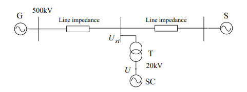
3 Existing Loss of Excitation Protection Scheme and Problems 3.1 Existing Loss of Excitation Protection SchemeThe schematic diagram of the synchronous condenser connect to the system is shown in Fig. 2. The voltage of the synchronous condenser SC terminal U is at the rated voltage level of 20 kV, and is connected to the 500 kV system via the step-up transformer. Ust is the high voltage side voltage of the step-up transformer, which is the system voltage. U is the synchronous condenser terminal voltage.
|
Fig.2 Synchronous condenser access system schematic |
The existing synchronous condenser loss of excitation protection scheme consists of three quantities to form the protection logic: reactive power, excitation voltage, and system voltage.
Reactive power reverse criterion is as follows:
| $ Q < - {Q_{set}} $ | (1) |
where Q is the per unit value of the synchronous condenser reactive power, the reference value is the rated power; Qset is the reactive power reverse setting value, which can be the value of the Ⅰ segment setting value QsetⅠ or the Ⅱ segment setting value QsetⅡ. Ⅰ segment setting value QsetⅠ = 0.11, Ⅱ segment setting value QsetⅡ = 0.55.
The excitation low voltage criterion is as follows:
| $ {U_r} < {U_{rset}} $ | (2) |
where Ur is the per unit value of the synchronous condenser excitation voltage, the reference value is the no load excitation voltage, the value is 0.25.
The system low voltage criterion is as follows:
| $ {U_{stpu}} < {U_{stset}} $ | (3) |
where Ustpu is the per unit value of the synchronous condenser system voltage, the reference value is the system rated voltage, the value is 0.9.
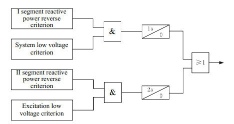
The protection logic block diagram is shown in Fig. 3.
|
Fig.3 Existing logic diagram of loss of excitation protection |
The protection is divided into two sections: the Ⅰ segment is the reactive power reverse criterion and the system low voltage criterion constitutes the AND logic. The Qset takes the value of the Ⅰ segment and the delay is 1s. Ⅱ segment is the reactive power reverse criterion and the excitation low voltage criterion constitutes the AND logic. The Qset takes the value of the Ⅱ segment and the delay is 2s.
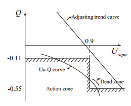
3.2 Problem AnalysisThe reactive power reverse criterion and the system low voltage criterion are mapped to the system voltage-reactive power characteristic plane as shown in Fig. 4.
|
Fig.4 System voltage-reactive power characteristic plane |
As can be seen from Fig. 4, the system voltage-reactive power operating characteristic curve is stepped. From the calculation formula of reactive power, the reactive power is proportional to the square of the system voltage, and the Ustpu–Q relationship curve should be a smooth parabola. Therefore, the stepped action characteristic curve does not conform to the Ustpu–Q relationship curve, and there is a dead zone as shown in Fig. 4.
Under normal operation, when system voltage decreases, the synchronous condenser emits inductive reactive power; when system voltage increases, the synchronous condenser absorbs the inductive reactive power. The function of synchronous condenser under normal operation is homeostatic regulation. The adjustment trend curve expresses the general trend. Under low system voltage conditions, when the regulation is normal, according to the adjustment trend curve, the synchronous condenser emits inductive reactive power, and the reactive power is positive and large; When the loss of excitation occurs, the synchronous condenser absorbs the inductive reactive power, and the reactive power is negative. The loss of excitation fault is contrary to the preset function of normal regulation, which can be called reverse adjustment. Therefore, under low system voltage conditions, the operating characteristic curve can reliably distinguish between normal regulation and loss of magnetic fault.
Under high system voltage conditions, when adjusting normally, according to the adjustment trend curve, the synchronous condenser absorbs the inductive reactive power, and the reactive power is negative; when the loss of excitation occurs, the synchronous condenser also absorbs the inductive reactive power, and the reactive power is negative. As mentioned earlier, the low excitation limit of the synchronous condenser is very low, close to the reactive power of the total loss of excitation. Therefore, the Ⅱ segment reactive power reverse setting (−0.55 pu) is between the low excitation limit (−0.5 pu) and the total loss of excitation (−0.6 pu). Under high system voltage conditions, when partial loss of excitation fault occurs, the leading reactive power may be higher than the low excitation limit. The II segment reactive power reverse criterion will be rejected, and the excitation voltage may also be higher than the excitation low voltage setting, and the protection will be rejected. That is, under high system voltage conditions, the loss of excitation and regulation cannot be reliably distinguished only by the magnitude of the reactive power of the phase ingress.
In summary, the stepped characteristic curve of the existing synchronous condenser loss of excitation protection has a dead zone; The low excitation limit is close to the reactive power of the phase in the case of full loss of excitation, and the protection may be rejected when part of the loss of excitation is caused by the high system voltage. Existing solutions cannot coordinate the sensitivity and safety of loss of excitation protection.
4 Novel Principle of Loss of Excitation Protection Based on Leading Rate 4.1 Selection of Characteristic PlaneThe excitation voltage is a physical quantity that reflects the nature of the synchronous condenser loss of excitation. When the synchronous condenser is loss of excitation fault, the most direct response is that the excitation voltage is reduced and the measured reactive power is negative. Under the same loss of excitation fault, when the terminal voltage is different, the excitation voltage is reduced to the same extent, but the leading reactive power of will be different. That is, the reactive power is easily affected by the operating conditions of the system, and is not a physical quantity that directly reflects the malfunction of the synchronous condenser.
As the physical quantity of the rotor side of the synchronous condenser, the excitation voltage is directly reflected on the stator side as the stator internal potential, which is expressed as follows:
| $ \dot E = \dot U + j{X_d}\dot I $ | (4) |
where
Under the same system operating conditions, when different levels of loss of excitation faults occur in the synchronous condenser, relationships between reactive power and excitation voltage, the steady-state value of the stator internal potential are shown in Fig. 5.

|
Fig.5 Relationship between reactive power and excitation voltage, the steady-state value of the stator internal potential |
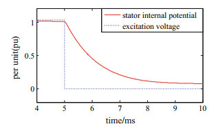
It can be seen from Fig. 5 that under different levels of loss of excitation fault, the excitation voltage is substantially the same as the steady state value of the stator internal potential amplitude. When the synchronous condenser has a full loss of excitation fault, the transient process of the excitation voltage and the amplitude of the stator internal potential is shown in Fig. 6. It can be seen from Fig. 6 that the excitation voltage and the amplitude of the stator internal potential have the same change trend after the loss of excitation fault. In the transient case, due to the action of the armature reaction, the reduction of the excitation voltage is reflected in the stator is a slowly changing process.
|
Fig.6 Transient process diagram of excitation voltage and amplitude stator internal potential after loss of excitation |
The steady state value of the stator internal potential is basically the same as the excitation voltage, and the transient change is slower than the excitation voltage, but the trend is the same. Therefore, the excitation voltage and the stator internal potential are selected to construct the rotor side and the stator side plane, respectively. The horizontal axis of the rotor side plane is the system voltage per unit value, the vertical axis is the excitation voltage per unit value; the horizontal axis of the stator side plane is the system voltage per unit value, and the vertical axis is the stator internal potential amplitude per unit value.
In this paper, the rotor side plane and the stator side plane are used to form a double criterion to improve the reliability of protection.
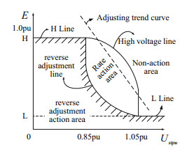
4.2 Characteristic CurveTaking the stator side plane as an example, the characteristic curves of the rotor side plane are identical. In this paper, the stator side plane is divided by a hyperbola as shown in Fig. 7. To avoid the dead zone caused by the stepped curve, the characteristic curve should be improved smooth. For the simplicity of function, high voltage line and reverse adjustment line are set as hyperbola. The curvature of high voltage line and reverse adjustment line are the same. The stator side plane is divided into a reverse adjustment action area, a rate action area, and a non-action area.
|
Fig.7 Area division of the stator side plane |
The reverse adjustment action zone is located below the H line, the reverse adjustment line, and the L line, and utilizes the reverse adjustment characteristic of the loss of excitation fault. Under low system voltage conditions, when normal regulation, according to the adjustment trend curve, the amplitude of the stator internal potential should be greater than 1 pu; When the loss of excitation fault occurs, the steady-state values of the excitation voltage and the amplitude of the stator internal potential are basically the same, the amplitude of the stator internal potential is less than 1 pu, and even the full loss of excitation is 0 pu. The stator inverse adjustment criterion based on hyperbolic function is as follows:
| $ \left\{ {\begin{array}{*{20}{c}} {E \le H\;\;\;0 < {U_{stpu}} < 0.85}\\ {E \le \frac{{0.05}}{{{U_{stpu}} - \lambda }} - \frac{{0.05}}{{1.05 - \lambda }} + L\;\;\;\;0.85 \le {U_{stpu}} \le 1.05}\\ {E \le L\;\;\;\;\;1.05 < {U_{stpu}}}\\ {\lambda = 0.95 - 0.1\sqrt {1 + \frac{1}{{H - L - 0.2}}} } \end{array}} \right. $ | (5) |
where E is the per unit value of the stator internal potential amplitude, and the rated voltage of the terminal is used as the reference value. The coefficient is confirmed by the location and curvature of hyperbola function. H is the high setting value threshold, H < 1, L is the low setting value threshold, L > 0. The high setting value threshold ensures that some of the loss of excitation faults fall into the reverse-regulating action zone under low system voltage conditions, and the low-set threshold ensures reliable fall into the reverse-regulating action zone when the full loss of excitation fault occurs.
The rate action zone is located between the reverse regulation line and the high voltage line to protect against partial loss of excitation faults under high system voltage conditions. The stator high voltage criterion is constructed based on the hyperbolic function as follows:
| $ \left\{ {\begin{array}{*{20}{c}} {E \le \frac{{0.05}}{{{U_{stpu}} - \eta }} - \frac{{0.05}}{{1.05 - \eta }} + L + 0.2\;\;\;\;\;\;0.85 \le {U_{stpu}} \le 1.05}\\ {E > \frac{{0.05}}{{{U_{stpu}} - \lambda }} - \frac{{0.05}}{{1.05 - \lambda }} + L\;\;\;\;\;\;\;0.85 \le {U_{stpu}} \le 1.05}\\ {\eta = 0.95 + 0.1\sqrt {1 + \frac{1}{{H - L - 0.2}}} } \end{array}} \right. $ | (6) |
Under high system voltage conditions, when normal regulation, according to the adjustment trend curve, the amplitude of stator internal potential should be less than 1 pu; When part of the loss of excitation fault, the amplitude of stator internal potential will also be less than 1 pu. It cannot be reliably distinguished between partial loss of excitation fault and normal regulation by relying on the characteristic plane alone. Therefore, in addition to the rate action region on the characteristic plane, a phase-rate detector is proposed to distinguish between partial loss of excitation faults and normal regulation under high system voltage conditions.
4.3 Leading Rate DetectorUnder high system voltage conditions, it is impossible to reliably distinguish the partial loss of excitation faults and normal adjustments by the reactive power, the amplitude of stator internal potential or the excitation voltage.
When the synchronous condenser is adjusted in steady state, the excitation adjustment is affected by the reactive outer loop control model. According to the engineering field test results, the fastest speed is 6–7 Mvar/s [13, 14]. But when loss of excitation fault occurs, the speed is in millisecond level [7], which is much faster than the steady state adjustment. Obviously, the loss of excitation fault is fast and the steady state adjustment is slow. The speed is an amount that can clearly distinguish between the loss of excitation fault and the steady state adjustment, and can be expressed from the stator side and the rotor side, respectively. On the stator side, the amount of change in the amplitude of stator internal potential at a certain time interval ΔtE is calculated to indicate the velocity; on the rotor side, the amount of change in the excitation voltage at a certain time interval Δtur is calculated to indicate the velocity. It can be seen from Fig. 6 that the change of the potential in the stator after the loss of magnetic fault is slower than the excitation voltage, so ΔtE is larger than Δtur. After a large number of simulation analysis, ΔtE is considered as 400 ms and Δtur is considered as 40 ms. Stator speed criterion and rotor speed criterion are as follows:
| $ E - {E_{ - \Delta {t_E}}} < {\rho _{set}} $ | (7) |
| $ {U_r} - {U_{r - \Delta {t_{ur}}}} < {\rho _{set}} $ | (8) |
where E-ΔtE is the value of the amplitude of stator internal potential before the ΔtE time interval, Ur-Δtur is the excitation voltage before the Δtur time interval, and ρset is the rate setting value. When loss of excitation fault occurs in the synchronous condenser, both the stator internal potential amplitude and the excitation voltage are reduced, and the variation is negative, so ρset is set to be less than zero. ρset is set to be less than the fastest steady-state adjustment rate, guarantee protection sensitivity when partial loss of excitation fault occurs, and guarantee sufficient protection sensitivity when full loss of excitation fault occurs.
Considering the transient operating conditions of the system voltage sudden increase, the synchronous condenser is adjusted for rapid phase in, which causes the excitation voltage and the stator internal potential to decrease, and the speed of the reduction is faster, making the stator speed criterion and the rotor speed criterion easy to maloperation. Therefore, increase the b block locking criterion as follows:
| $ {U_{stpu}} - {U_{stpu - \Delta {t_s}}} > {z_{set}} $ | (9) |
where Ustpu-Δts is the system voltage per unit value before the Δts time interval, and zset is the blocking setting value and greater than zero. When a loss of excitation fault occurs, the system voltage decreases, and the system voltage increment is negative; When the increment of the system voltage within a certain time interval is greater than the blocking setting value, it is considered that the system is in the transient state of the system voltage sudden increase, and then block rate criterion ensures that the protection is reliable and does not maloperation.
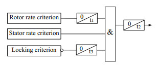
The leading rate detector consists of a stator rate criterion, a rotor rate criterion, and a blocking criterion. The action logic is shown in Fig. 8, and the operation result broadening is t2. Since the calculation time interval of the excitation voltage change rate is much smaller than the stator internal potential, the moment which the rotor speed criterion is satisfied may be earlier than the stator rate criterion. Therefore, the operation result broadening of the rotor speed criterion is set to t1 to wait for the stator rate criterion. The leading rate detector operates when both the rotor rate criterion and the stator rate criterion are satisfied. Once the amount of change in the system voltage satisfies the blocking criterion, the phase rate detector is blocked for a period of time t3 to prevent protection from maloperation.
|
Fig.8 Leading rate detector action logic diagram |
4.4 Overall Criterion
Using the stator and rotor dualization criterion, for the stator side plane, such as Sect. 3.2, the stator reverse adjustment criterion and the stator high voltage criterion are constructed based on the hyperbolic function. Similarly, for the rotor side plane, the rotor reverse adjustment criterion based on the hyperbolic function and the rotor high voltage criterion are as follows:
| $ \left\{ {\begin{array}{*{20}{c}} {{U_r} \le H\;\;\;\;\;0 < {U_{stpu}} < 0.85}\\ {{U_r} \le \frac{{0.05}}{{{U_{stpu}} - \lambda }} - \frac{{0.05}}{{1.05 - \lambda }} + L\;\;\;\;\;\;\;0.85 \le {U_{stpu}} \le 1.05}\\ {{U_r} \le L\;\;\;\;1.05 < {U_{stpu}}}\\ {\lambda = 0.95 - 0.1\sqrt {1 + \frac{1}{{H - L - 0.2}}} } \end{array}} \right. $ | (10) |
| $ \left\{ {\begin{array}{*{20}{c}} {{U_r} \le \frac{{0.05}}{{{U_{stpu}} - \eta }} - \frac{{0.05}}{{1.05 - \eta }} + L + 0.2\;\;\;\;\;\;0.85 \le {U_{stpu}} \le 1.05}\\ {{U_r} > \frac{{0.05}}{{{U_{stpu}} - \lambda }} - \frac{{0.05}}{{1.05 - \lambda }} + L\;\;\;\;\;\;\;0.85 \le {U_{stpu}} \le 1.05}\\ {\eta = 0.95 + 0.1\sqrt {1 + \frac{1}{{H - L - 0.2}}} } \end{array}} \right. $ | (11) |
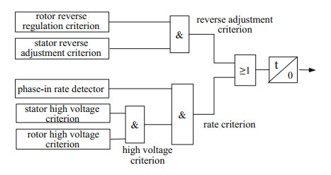
The reverse adjustment criterion is obtained by the stator reverse adjustment criterion being AND with the rotor reverse regulation criterion. The high voltage criterion is obtained by the stator high voltage criterion being AND with the rotor high voltage criterion. The rate criterion is obtained by the high voltage criterion being AND with the leading rate detector. The inverse adjustment criterion is OR with the rate criterion and finally outputs via a delay t. The overall logic block diagram of the novel protection principle is shown in Fig. 9.
|
Fig.9 The overall logic block diagram of the novel protection principle |
The reverse adjustment criterion is used to protect the full loss of excitation fault and partial loss of excitation fault under low system voltage conditions; Rate criterion are used to protect against partial loss of excitation faults under high system voltage conditions. The novel scheme consists of the inverse adjustment criterion and the rate criterion "OR", which can reliably protect the full loss of excitation fault and part of the loss of excitation fault, and the protection is reliable and does not maloperation under the conditions of system voltage sudden increase.
In summary, the novel protection principle adopts a hyperbolic characteristic curve, which avoids the dead zone problem caused by the stepped curve. In the rate criterion, a leading rate detector is introduced to distinguish the partial loss of excitation fault and regulation under high system voltage by the magnitude of the rate, which improves the reliability and sensitivity of the protection.
5 SimulationA simulation model is built in PSCAD according to Fig. 2. The synchronous condenser rated capacity is 300 Mvar, the rated voltage is 20 kV, and the direct-axis synchronous reactance is 1.53 pu. The step-up transformer rated capacity is 360 MVA, conversion ratio is 530/20 kV, and short-circuit impedance is 12%. The length of line between synchronous condenser and synchronous generator is 100 km; the length of line between synchronous condenser and equivalent system source is 50 km. The positive sequence equivalent system impedance is 5.4 Ω.The angle of equivalent system impedance is 85°.
5.1 Existing Protection SchemeWhen the system voltage is 0.99 pu and loss of excitation fault occurs, the characteristic plane motion trajectory of the existing synchronous condenser loss of excitation protection is shown in Fig. 10. As can be seen from Fig. 10, the low voltage criterion of the existing protection system does not operate, and the II segment reactive power reverse criterion does not operate. It can be seen from Fig. 3 that the existing protections Ⅰ and Ⅱ segment do not operate. That is, when the partial loss of excitation fault is under the high system voltage, the existing protection will miss trip.

|
Fig.10 Existing protection characteristic plane motion track |
5.2 Novel Principle of Protection
Full loss of excitation fault. The excitation voltage set to zero artificially, full loss of excitation fault occurs. The stator side plane motion characteristics and the rotor side plane motion characteristics of the synchronous condenser are shown in Figs. 11 and 12, respectively.

|
Fig.11 Stator side plane motion characteristics during full loss of excitation |

|
Fig.12 Rotor side plane motion characteristics during full loss of excitation |
It can be seen from Figs. 10 to 11 that the stator internal potential and excitation voltage before the fault are located in the non-action zone. After the loss of excitation fault, the stator internal potential slowly falls into the reverse adjustment zone, and the excitation voltage directly enters the reverse adjustment zone. The stator reverse adjustment criterion and the rotor reverse adjustment criterion are all reliable action. As can be seen from Fig. 9, the reverse adjustment criterion is reliable action. That is, when the total loss of excitation fault occurs, the novel scheme operates reliably.
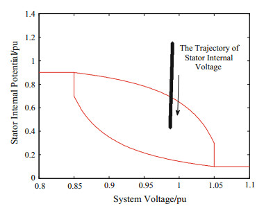
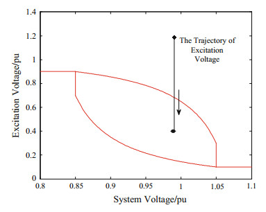
Partial loss of excitation fault. The excitation voltage set to less value artificially, partial loss of excitation fault occurs. When the system voltage is 0.99 pu, partial loss of excitation fault occurs in the synchronous condenser, and the stator side plane motion characteristics and the rotor side plane motion characteristics of the synchronous condenser are shown in Figs. 13 and 14, respectively.
|
Fig.13 Stator side plane motion characteristics during partial loss of excitation |
|
Fig.14 Rotor side plane motion characteristics during partial loss of excitation |
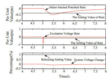
It can be seen from Figs. 13 to 14 that the stator internal potential and excitation voltage before the fault are located in the non-action zone. After partial loss of excitation fault, the stator internal potential slowly falls into the rate action zone, and the excitation voltage directly enters the rate action zone. The stator high voltage criterion and the rotor high voltage criterion operate reliably. As can be seen from Fig. 9, the high voltage criterion operates. Whether the protection can be reliably operated depends on whether the leading rate detector is reliable or not. The results of the rotor rate criterion, the stator rate criterion, and the blocking criterion are shown in Fig. 15, respectively. ρset is set as −0.15 and Zset is set as 0.01 according to simulation results.
|
Fig.15 The results of the rotor rate criterion, the stator rate criterion, and the blocking criterion |
As can be seen from Fig. 15, the moment which the excitation voltage rate is lower than the rate setting value is earlier than the stator internal potential rate, and the moment which the rotor rate criterion is satisfied is earlier than the stator rate criterion. As can be seen from Fig. 8, the rotor speed criterion broadening t1 time is "AND" with the stator speed criterion, and the result is reliable operation.
The high voltage criterion and the phase advance rate detector operate reliably. As can be seen from Fig. 9, the rate criterion is reliable action. That is, when system is under high voltage and occur the partial loss of excitation fault, the novel scheme can operate reliably.
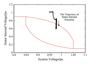
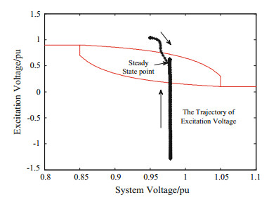
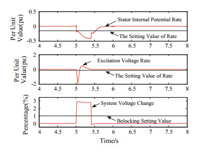
System voltage sudden increase. When the system voltage suddenly increases from 0.95 to 0.97 pu, the stator internal potential and excitation voltage decrease, and the waveform changes with time as shown in Fig. 16. The stator side plane operating characteristics and the rotor side plane operating characteristics are as shown in Figs. 17 and 18, respectively. After the system voltage suddenly increases, the stator internal potential and excitation voltage enter the rate action zone, and the stator high voltage criterion and the rotor high voltage criterion are all reliable action. As can be seen from Fig. 9, the high voltage criterion operates. The results of the rotor rate criterion, the stator rate criterion, and the blocking criterion are shown in Fig. 19, respectively. Both the stator speed criterion and the rotor speed criterion are miss trip. Since the increment of the system voltage in a certain time interval is greater than the block setting value, the blocking criterion is reliably operated, and the leading rate detector is reliably inoperative. It can be seen from Fig. 9 that the rate criterion is reliable and does not operate, and the novel scheme is reliable and does not maloperation.

|
Fig.16 Stator internal potential and excitation voltage waveform |
|
Fig.17 Stator side plane motion characteristics when system voltage suddenly increases |
|
Fig.18 Rotor side plane motion characteristics when system voltage suddenly increases |
|
Fig.19 Rotor speed criterion, stator speed criterion and blocking criterion result when system voltage suddenly increases |
In summary, under high system voltage condition, the existing protection may refuse to operate when partial loss of excitation occurs, and the novel scheme reliably operates due to the action of the leading rate detector. The novel scheme operates reliably under the conditions of full loss of excitation and partial loss of excitation, and it does not operate reliably when sudden increase of system voltage occurs, which improves the reliability and sensitivity of protection, and the performance is better than the existing protection scheme.
6 ConclusionA novel loss of excitation protection principle for synchronous condenser based on leading rate is proposed in this paper. The leading rate detector based on stator internal potential and excitation voltage is proposed to distinguish partial loss of excitation and normal regulation under high system voltage condition. The PSCAD simulation results show that under the high system voltage and partial loss of excitation fault conditions, the existing protection scheme refuse to operate, and the novel protection principle operates reliably due to the action of the leading rate detector. The novel loss of excitation protection principle for synchronous condenser operates reliably under both full loss of excitation and partial loss of excitation conditions, and does not operate reliably when sudden increase of system voltage occurs. The novel loss of excitation protection principle for synchronous condenser has high sensitivity and reliability, and has a good applicability in practical engineering project.
| 1. |
Zhou X, Lu Z, Liu Y, Chen S (2014) Development models and key technologies of future grid in China. Proc CSEE
34(29): 4999-5008. (  0) 0) |
| 2. |
Zeng Q (2015) Techno-economic analysis of UHVAC and UHVDC power transmission systems. Power Syst Technol
39(2): 341-348. (in Chinese) (  0) 0) |
| 3. |
Tu J, Zhang J, Wang J, et al (2015) Mechanism analysis on the sending-side instability caused by the receiving-side contingencies of large-scale HVDC asynchronous interconnected power systems. Proc CSEE
35(21): 5492-5499. (  0) 0) |
| 4. |
Wang Y, Zhang Y, Zhou Q, et al (2017) Study on application of new generation large capacity synchronous condenser in power grid. Power Syst Technol
41(1): 28-34. (in Chinese) (  0) 0) |
| 5. |
Liu Z, Zhang Q, Wang Y, et al (2015) Research on reactive compensation strategies for improving stability level of sending-end of 750 kV grid in Northwest China. Proc CSEE
35(5): 1015-1022. (in Chinese) (  0) 0) |
| 6. |
Teleke S, Abdulahovic T, Thiringer T, et al (2008) Performance comparison of synchronous condenser and SVC. IEEE Trans Power Delivery
23(3): 1606-1612. DOI:10.1109/TPWRD.2007.916109 (  0) 0) |
| 7. |
Luo L, Li Z, Song X, et al (2016) Study on the relay protection scheme of high-capacity synchronous condenser. Hunan Elect Power
36(5): 26-30. (  0) 0) |
| 8. |
Lin Q (1994) Analysis and research on the loss of excitation protection of synchronous condenser. Fujian Power Electr Eng
1: 1-5. (  0) 0) |
| 9. |
Wang D (1984) Synchronous condenser loss of excitation operation characteristics and recommended protection scheme. North China Elect Power
(1): 16-23. (  0) 0) |
| 10. |
Dongxia Z, Juanhong N, Rui Y, et al (2016) SFC start and relay protection of 300 Mvar large synchronous condenser. Power Syst Prot Control
44(20): 160-164. (  0) 0) |
| 11. |
Zheng T, Yu Q, Zhan R, et al (2018) Impact of synchronous condenser access on generator loss of excitation protection. Power Syst Prot Control
46(4): 50-56. (  0) 0) |
| 12. |
Xie B, Xu K, Liu J, et al (2018) Study on the principle and setting method of low excitation limit setting for excitation regulator. Power Syst Prot Control
46(8): 142-147. (  0) 0) |
| 13. |
Wu K, Fang L, Lu C, et al (2018) Discussion on coordinated control strategy for large synchronous compensator and reactive power. Zhejiang Electric Power
37(2): 36-41. (  0) 0) |
| 14. |
Shi X, Wei M, Han J, et al (2017) Research on control strategy of large synchronous condensers. Electric Power
50(12): 44-50. (  0) 0) |
| 15. |
National Energy Administration (2016) Guide on leading power factor operation test of synchronous generator: DL/T 1523—2016.
China Electric Power Press, Beijing.
(  0) 0) |
| 16. |
Guo C, Yu Z, Yin X (2012) Coordinative setting calculation of minimum-excitation limit and loss-of excitation protection for generator. ProcCSEE
32(28): 129-132. (  0) 0) |
 2020 : 3-22 DOI: 10.1007/978-981-13-9779-0_1


