A millimeter-wave unmanned aerial vehicle (UAV) cellular multiuser network is investigated based on beamspace multiple-input and multiple-out put. A beam selection scheme assisted by UAV mobility is proposed. At first, an optimal deployment position of UAV base station is identified with the aim of reducing power leakage problem among users. Afterwards, a simple power focused beam selection criterion called beam reselection is introduced to avoid the problem that the same beam is selected by different users, which will cause the waste of radio-frequency chains. Numerical simulations results show that the proposed scheme achieve near optimal achievable sum rate performance and higher power efficiency compared with conventional beam selection scheme.
在无人机毫米波多用户通信网络中,基于波束空间多输入多输出系统提出了一种利用无人机移动特性的波束选择方法.首先,以减少用户间的能量泄漏为目标设计了无人机基站的最优部署位置;然后,为避免不同用户选择同一波束造成射频链路浪费的情况,提出了一种通过用户接收能量衡量的波束重新选择准则.仿真结果表明,相比传统的波束选择方法,所提方法可以实现接近最优的系统和速率性能以及更高的能量效率.
Millimeter-wave (mm-wave) communication has been considered as one of key enabling technologies in fifth generation of mobile communications system (5G) wireless communication system[1]. Mm-wave multiple-input and multiple-output (MIMO) communication could achieve multi-Gbit/s data rates due to its large amount of available spectrum resource (30~300GHz)[2]. Another potential technology for 5G communication is unmanned aerial vehicles (UAVs) aided wireless communication[3] with the benefit of low cost and high maneuverability. UAVs equipped with communication devices could be deployed as aerial base station (BS) and provide communication services for ground users when there is a temporary event or the communication infrastructure is destroyed after a natural disaster[4]. Combining mm-wave communication with UAV cellular is considered as a promising method to efficiently support high data rate[5].
In order to compensate the severe path loss in mm-wave communication, a large number of antenna arrays are needed to form narrow directional beams and high array gains[6]. In the conventional MIMO communication system, each antenna is connected with a radio-frequency (RF) chain[7], which becomes impossible to realize in mm-wave communication system because of the high power consumption and high cost. The concepts of beamspace MIMO (B-MIMO) are proposed in Ref.[7] based on the sparsity of mm-wave channels to reduce the hardware complexity. The channels are transformed into beamspace channel by utilizing discrete Fourier transform (DFT) and only a small number of beams are selected[8-9]. The conventional beam selection scheme proposed in Ref.[8] selects beams which contain most channel power. But the same beam may be selected by different users, which will cause the waste of RF chains and power leakage problem[10].
In this paper, a beam selection scheme assisted by UAV mobility called BRS-UMis designed for an mm-wave UAV cellular multiuser network. By exploiting the mobility of the UAV BS, the optimal deployment position is identified to reduce the power leakage problem. And a power focused beam reselection scheme is proposed to avoid that the same beam is selected by different users. Numerical results indicate the proposed scheme achieves near optimal achievable sum rate performance and higher power efficiency compared with conventional fixed BS beam selection scheme.
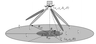
1 System ModelFig. 1 shows an mm-wave UAV cellular multiuser network. A UAV control station is located in the cell center. The radius of the cell is Rcell. And a rotary wing UAV such as a quadcopter, which is able to stay stationary in the air or move in any direction[3], is deployed as UAV BS. The height of UAV BS hu is fixed and the UAV BS could only adjust its position in the red inner circular region whose radius is Rin. Rin is determined with the control range of the UAV control station. A uniform planar array (UPA) is equipped on the UAV BS, Nh and Nv is the number of antenna elements in rows and columns. N=NhNv is the total number of antenna elements. And there are K single antenna ground users located in the cell, who are served by the UAV BS simultaneously. The locations of ground users are assumed to be known and remain unchanged at UAV BS through global positioning system (GPS). The scenario in this paper can be a sports events or a vocal concert, people who attend the events usually have a fixed seat. Their locations can remain unchanged during the period of the events and UAVs are deployed to offload the traditional communication service or enhance the quality of communication in such a hot spot area[3].

|
Figure 1 Illustration of a mm-wave UAV cellular multiuser network |
The received symbol vector of K ground users is given by
| $ \mathit{\boldsymbol{y}} = {\mathit{\boldsymbol{H}}^{\rm{H}}}\mathit{\boldsymbol{Fs}} + \mathit{\boldsymbol{n}} $ | (1) |
where H=[h1, h2, …, hK] and hk∈CN×1 is the channel vector between the UAV BS and the kth ground user, F∈CN×K is the precoding matrix. In the conventional MIMO communication system, the number of RF chains NRF is equal to N, which is impractical for mm-wave system because N is very large. In addition, s is the transmitted symbol vector for K ground users and n is the additive white Gaussian noise (AWGN) vector.
In this paper, we focus on the downlink transmission when the UAV BS stays stationary in the air and frequency division duplex (FDD) mode is considered. And the spatial multipath channel model is adopted, the downlink channel vector between the kth ground user and the UAV BS is written as[7]
| $ {\mathit{\boldsymbol{h}}_k} = {\beta _{k,0}}\alpha \left( {{\gamma _{k,0}},{\psi _{k,0}}} \right) + \sum\limits_{l = 1}^L {{\beta _{k,l}}\alpha \left( {{\gamma _{k,l}},{\psi _{k,l}}} \right)} $ | (2) |
where βk, 0 and βk, l are the complex path losses of the LOS and the lth non-line-of-sight (NLOS) path. α(γ, ψ) is the N×1 steering vector of the UPA array and is given by[11]
| $ \begin{array}{*{20}{c}} {\alpha \left( {\gamma ,\psi } \right) = {\alpha _{{\rm{el}}}}\left( \gamma \right) \otimes {\alpha _{{\rm{az}}}}\left( \psi \right)}\\ {{\alpha _{{\rm{el}}}}\left( \gamma \right) = \frac{1}{{\sqrt {{N_v}} }}{{\left[ {{{\rm{e}}^{ - {\rm{j2 \mathsf{ π} }}i\gamma }}} \right]}_{i \in \mathit{\Gamma }\left( {{N_v}} \right)}}}\\ {{\alpha _{{\rm{az}}}}\left( \gamma \right) = \frac{1}{{\sqrt {{N_h}} }}{{\left[ {{{\rm{e}}^{ - {\rm{j2 \mathsf{ π} }}k\psi }}} \right]}_{k \in \mathit{\Gamma }\left( {{N_h}} \right)}}} \end{array} $ | (3) |
where
Denote the N×N beamforming matrix as
| $ {\mathit{\boldsymbol{H}}_b}{\rm{ = }}\mathit{\boldsymbol{UH}}{\rm{ = }}\left[ {\mathit{\boldsymbol{h}}_1^b,\mathit{\boldsymbol{h}}_2^b, \cdots ,\mathit{\boldsymbol{h}}_K^b} \right] $ | (4) |
| $ {\mathit{\boldsymbol{y}}_s} \approx \mathit{\boldsymbol{H}}_s^{\rm{H}}{\mathit{\boldsymbol{F}}_s}\mathit{\boldsymbol{s}} + \mathit{\boldsymbol{n}} $ | (5) |
where
Compared with conventional fixed BS, the UAV BS brings another degree of freedom—UAV mobility, which could be utilized to help improve network performance. In this section, a beam selection scheme assisted by UAV mobility called BRS-UM for a mm-wave UAV cellular network is proposed. The proposed scheme contains two steps. At first, the optimal position of UAV BS is identified in order to reduce power leakage problem. Subsequently, a simple power focused beam selection criterion called beam reselection (BRS) is executed and guaranteed to allocate a unique beam for each user.
2.1 Problem FormulationAs shown in Fig. 1, the UAV position is denoted as
| $ \left| {\cos {\theta _k}} \right| = \frac{{{R_{k,{\rm{u}}}}}}{{\sqrt {R_{k,{\rm{u}}}^2 + h_{\rm{u}}^2} }} $ | (6) |
| $ \left| {\sin {\theta _k}\cos {\varphi _k}} \right| = \frac{{{h_{\rm{u}}}}}{{\sqrt {R_{k,{\rm{u}}}^2 + h_{\rm{u}}^2} }}\left| {\cos \left( {{\varphi _{k,0}} + \delta } \right)} \right| $ | (7) |
where φk, 0 represents the azimuth AOD relative to the UAV BS when δ=0 and is given by
| $ {\varphi _{k,0}} = \left\{ {\begin{array}{*{20}{c}} {\arccos \frac{{{x_k} - {x_{\rm{u}}}}}{{{R_{k{\rm{u}}}}}},\;\;\;\;\;\;\;\;\;\;\;{y_k} - {y_{\rm{u}}} \ge 0}\\ {\arccos \frac{{{x_k} - {x_{\rm{u}}}}}{{{R_{k{\rm{u}}}}}} + {\rm{ \mathsf{ π} }},\;\;\;\;\;\;\;{y_k} - {y_{\rm{u}}}{\rm{ < 0}}} \end{array}} \right. $ | (8) |
The ground users are assumed to be static in this paper, so
Property 1 When there exists a pair of
Proof Define the jth row of U as
| $ \begin{array}{l} h_k^b\left( j \right) = {\beta _k}\left\{ {\left[ {\frac{1}{{{N_v}}}\frac{{\sin \left( {{\rm{ \mathsf{ π} }}{N_v}\left( {{{\bar \gamma }_m} - \frac{1}{2}\cos {\theta _k}} \right)} \right)}}{{\sin \left( {{\rm{ \mathsf{ π} }}\left( {{{\bar \gamma }_m} - \frac{1}{2}\cos {\theta _k}} \right)} \right)}}} \right]} \right. \times \\ \left. {\left[ {\frac{1}{{{N_h}}}\frac{{\sin \left( {{\rm{ \mathsf{ π} }}{N_h}\left( {{{\bar \psi }_n} - \frac{1}{2}\sin{\theta _k}\cos {\varphi _k}} \right)} \right)}}{{\sin \left( {{\rm{ \mathsf{ π} }}\left( {{{\bar \psi }_n} - \frac{1}{2}\sin{\theta _k}\cos {\varphi _k}} \right)} \right)}}} \right]} \right\} \end{array} $ | (9) |
When
According to Ref.[8], when
| $ \begin{array}{l} {\rm{di}}{{\rm{s}}_{{\rm{el}}}}\left( {\cos {\theta _k}} \right) = \min \left[ {\bmod \left( {\frac{1}{2}\left| {\cos {\theta _k}} \right|,\frac{1}{{{N_v}}}} \right),} \right.\\ \left. {\frac{1}{{{N_v}}} - \bmod \left( {\frac{1}{2}\left| {\cos {\theta _k}} \right|,\frac{1}{{{N_v}}}} \right)} \right] \end{array} $ | (10) |
Similarly, the minimum distance between
| $ \begin{array}{*{20}{c}} {{\rm{di}}{{\rm{s}}_{{\rm{az}}}}\left( {\sin{\theta _k}\cos {\varphi _k}} \right) = }\\ {\min \left[ {\bmod \left( {\frac{1}{2}\left| {\sin{\theta _k}\cos {\varphi _k}} \right|,\frac{1}{{{N_h}}}} \right),} \right.}\\ {\left. {\frac{1}{{{N_h}}} - \bmod \left( {\frac{1}{2}\left| {\sin{\theta _k}\cos {\varphi _k}} \right|,\frac{1}{{{N_h}}}} \right)} \right]} \end{array} $ | (11) |
And the optimization problem is formulated as
| $ \begin{array}{l} \forall k,\left\{ \begin{array}{l} \mathop {\min }\limits_{\left( {{x_{\rm{u}}},{y_{\rm{u}}},{h_{\rm{u}}},\delta } \right)} {\rm{di}}{{\rm{s}}_{{\rm{el}}}}\left( {\cos {\theta _k}} \right)\\ \mathop {\min }\limits_{\left( {{x_{\rm{u}}},{y_{\rm{u}}},{h_{\rm{u}}},\delta } \right)} {\rm{di}}{{\rm{s}}_{{\rm{az}}}}\left( {\sin{\theta _k}\cos {\varphi _k}} \right) \end{array} \right.\\ \;\;\;\;\;\;\;\;\;\;{\rm{s}}.{\rm{t}}.x_{\rm{u}}^2 + y_{\rm{u}}^2 \le R_{{\rm{in}}}^2 \end{array} $ | (12a) |
| $ \delta \in \left[ { - \frac{1}{2}{\rm{ \mathsf{ π} ,}}\frac{1}{2}{\rm{ \mathsf{ π} }}} \right] $ | (12b) |
However, the above optimization problem is difficult to solve since the modification of UAV BS's position will change the (θ, φ) of all ground users. Then we relax the optimization problem into a sub-optimization format:
| $ \mathop {\min }\limits_{\left( {{x_{\rm{u}}},{y_{\rm{u}}},{h_{\rm{u}}},\delta } \right)} \sum\limits_{k = 1}^K {{\rm{di}}{{\rm{s}}_{{\rm{el}}}}\left( {\cos {\theta _k}} \right)} $ | (13) |
| $ \mathop {\min }\limits_{\left( {{x_{\rm{u}}},{y_{\rm{u}}},{h_{\rm{u}}},\delta } \right)} \sum\limits_{k = 1}^K {{\rm{di}}{{\rm{s}}_{{\rm{az}}}}\left( {\sin{\theta _k}\cos {\varphi _k}} \right)} $ | (14) |
In the following, a method to identify the optimal position of UAV BS which achieves Eq.(13) and Eq.(14) is described. The position of UAV BS has two parts: hovering location
| $ \mathit{\Phi } = \left\{ {\left( {{x_{\rm{u}}},{y_{\rm{u}}},{h_{\rm{u}}}} \right):{x_{\rm{u}}} = {r_{\rm{u}}}\cos {\alpha _{\rm{u}}},{y_{\rm{u}}} = {r_{\rm{u}}}\sin {\alpha _{\rm{u}}}} \right\} $ | (15) |
where ru=iΔr, i=0, 1, …, Nr and αu=tΔα, t=0, 1, …, Nα, Δr and Δα are the minimum resolution determined by the minimum move range of UAV. Nr=
Similarly, a set Θ that contains all the candidate orientation angles of UAV BS is defined as
| $ \begin{array}{*{20}{c}} {\mathit{\Theta } = \left\{ {\delta :\delta = - \frac{1}{2}{\rm{ \mathsf{ π} }} + q\Delta \delta ,q = 0,1, \cdots ,{N_\delta }} \right\},}\\ {{N_\delta } = \left\lfloor {\frac{{\rm{ \mathsf{ π} }}}{{\Delta \delta }}} \right\rfloor } \end{array} $ | (16) |
From Eq.(6), Eq.(7) and Eq.(8), it is found that |cos θk| is merely determined by the hovering location of UAV BS and |sin θkcos φk| is determined by the both parts. Based on this, a method is proposed to identify the optimal position of UAV BS
① Based on all the positions of ground users known at UAV BS,
② Based on the result
In this way, the optimal position of UAV BS is identified.
2.3 Step 2: Beam ReselectionIn this section, a simple power focused beam selection criterion called beam reselection is introduced. After the UAV BS is deployed in the optimal position obtained from Step 1, the largest beam in the beamspace channel vector is selected for each ground user firstly. When the same beam is selected by more than one user, it will cause performance loss and the waste of corresponding RF chains[9]. So beam reselection process is required for users who select the same beam.
Define bk∈Ω is the indice of selected beam of kth ground user and Ω={1, 2, …, N} is the complete set of all indices. Then divide the users in two subsets: same beam user subset ASU and different beam user subset
① Divide all K users into ASU and ADU according the beams they selected. Afterwards, divide all the beams into ΩS and ΩUNS according to user division;
② For users in ASU, for example,
③ Repeat ①-② until ASU is empty and every user select a unique beam, hence |ΩS|=K.
Since for each user the largest beams are allocated with the current set in each iteration. And a unique beam would be allocated to each user in the end of the algorithm.
3 Numerical Results and AnalysisIn this section, numerical results are presented to analyze the performance of the proposed BRS-UM scheme compared with the conventional fixed BS 1/2-beam selection (1/2BS-FB) scheme, where The base station is fixed at the original (0, 0)[8]. The ground users are uniformly distributed in the cell. According to Friis transmission formula[12],
|βk|2=
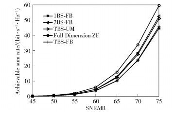
As shown in Fig. 2, the system achievable sum rate with different beam selection schemes is presented. And the full dimension ZF system is also provided for comparison. It is observed that the proposed BRS-UM scheme achieves a better performance than 1BS-FB scheme and only shows a less gap from 2BS-FB scheme. The performance of beam reselection scheme for fixed BS (BRS-FB) is also presented and only achieves small improvement compared with 1BS-FB. It implies that power leakage problem is the main reason to the system performance loss. And the power leakage problem is reduced by exploiting UAV mobility. Although the full dimension ZF system achieves the best performance due to all beams are selected, NRF=N, it suffers from high RF hardware complexity.

|
Figure 2 Simulation results of achievable sum rate versus SNR with different benchmarks |
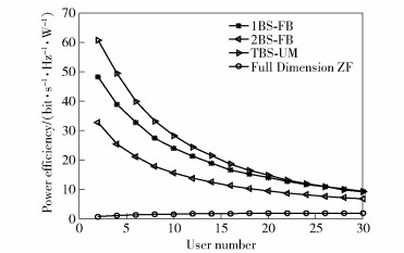
Fig. 3 shows the power efficiency of different schemes with different number of users. It is observed that the proposed BRS-UM scheme achieves the best power efficiency performance because BRS-UM scheme uses fewer RF chains and achieves near optimal sum rate. When the number of users becomes larger, the power efficiency both becomes worse due to the increase of the number of RF chains. And the full dimension ZF achieves the worst power efficiency because of high number of RF chains.

|
Figure 3 Simulation results of power efficiency versus user number with different benchmarks |
In this paper, we have proposed a beam selection scheme assisted by UAV mobility for a mm-wave UAV cellular multiuser network. The proposed BRS-UM scheme has two main advantages: 1) the power leakage problem among the users is greatly reduced by making use of UAV mobility; 2) beam reselection avoids that the same beam is selected by different users. Numerical results demonstrate that the proposed BRS-UM scheme achieves almost optimal sum rate performance and higher power efficiency compared with conventional fixed BS beam selection scheme. Extending the BRS-UM scheme to a mobile scenario, where the ground users are not static, is our future work.
| [1] |
Xiao Ming, Mumtaz S, Huang Yongming, et al. Millimeter wave communications for future mobile networks[J]. IEEE Journal on Selected Areas in Communications, 2017, 35(9): 1909-1935. doi: 10.1109/JSAC.2017.2719924 |
| [2] |
Ghosh A, Thomas T A, Cudak M C, et al. Milli-meter-wave enhanced local area systems: a high-data-rate approach for future wireless networks[J]. IEEE Journal on Selected Areas in Communications, 2014, 32(6): 1152-1163. doi: 10.1109/JSAC.2014.2328111 |
| [3] |
Zeng Yong, Zhang Rui, Lim T J. Wireless communications with unmanned aerial vehicles: opportunities and challenges[J]. IEEE Communications Magazine, 2016, 54(5): 36-42. doi: 10.1109/MCOM.2016.7470933 |
| [4] |
Merwaday A, Guvenc I. UAV assisted hetero-geneous networks for public safety communica-tions[C]// 2015 IEEE Wireless Communications and Networking Conference Workshops (WCNCW). New York: IEEE Press, 2015: 329-334.
|
| [5] |
Xiao Zhenyu, Xia Pengfei, Xia Xianggen. Enabling UAV cellular with millimeter-wave communication: potentials and approaches[J]. IEEE Communications Magazine, 2016, 54(5): 66-73. doi: 10.1109/MCOM.2016.7470937 |
| [6] |
Roh W, Seol J Y, Park J, et al. Millimeter-wave beamforming as an enabling technology for 5G cellular communications: theoretical feasibility and prototype results[J]. IEEE Communications Magazine, 2014, 52(2): 106-113. doi: 10.1109/MCOM.2014.6736750 |
| [7] |
Brady J, Behdad N, Sayeed A M. Beamspace MIMO for millimeter-wave communications: system architecture, modeling, analysis, and measurements[J]. IEEE Transactions on Antennas and Propagation, 2013, 61(7): 3814-3827. doi: 10.1109/TAP.2013.2254442 |
| [8] |
Sayeed A, Brady J. Beamspace MIMO for high-dimensional multiuser communication at millimeter-wave frequencies[C]//2013 IEEE Global Communications Conference (GLOBECOM). New York: IEEE Press, 2013: 3679-3684.
|
| [9] |
Gao Xinyu, Dai Linglong, Chen Zhijie, et al. Near-optimal beam selection for beamspace mmWave massive MIMO systems[J]. IEEE Communications Letters, 2016, 20(5): 1054-1057. doi: 10.1109/LCOMM.2016.2544937 |
| [10] |
Zhao Jianwei, Gao Feifei, Jia Weimin, et al. Angle domain hybrid precoding and channel tracking for millimeter wave massive MIMO systems[J]. IEEE Transactions on Wireless Communications, 2017, 16(10): 6868-6880. doi: 10.1109/TWC.2017.2732405 |
| [11] |
Han Yu, Zhang Haochuan, Jin Shi, et al. Investigation of transmission schemes for millimeter-wave massive MU-MIMO systems[J]. IEEE Systems Journal, 2017, 11(1): 72-83. doi: 10.1109/JSYST.2015.2481089 |
| [12] |
Friis H. A note on a simple transmission for-mula[J]. Proceedings of the IRE, 1946, 34(5): 254-256. doi: 10.1109/JRPROC.1946.234568 |


