文章信息
- Yury V. BOGACHEV, Mikhail N. KNYAZEV, Yaroslav Yu. MARCHENKO
- Yury V. BOGACHEV, Mikhail N. KNYAZEV, Yaroslav Yu. MARCHENKO
- 紧凑型电子自旋共振(ESR)仪
- Compact ESR Equipment
- 波谱学杂志, 2016, 33(1): 27-36
- Chinese Journal of Magnetic Resonance, 2016, 33(1): 27-36
- http://dx.doi.org/10.11938/cjmr20160102
-
文章历史
- 收稿日期: 2015-09-02
- 收修改稿日期: 2016-01-23
2. Resonance-M, Ltd., Saint-Petersburg State Electrotechnical University, Saint-Petersburg, 197376, Russia
2. Resonance-M, Ltd., Saint-Petersburg State Electrotechnical University, Saint-Petersburg, 197376, Russia
Well known produced compact ESR spectrometers[1, 2, 3, 4, 5]have a closed architecture and they are oriented only for separate specific ESR applications. But some applications require a free access to the sample, for example, when it is necessary to conduct experiments with a light irradiation of the sample or to change and control the sample’s temperature.
It is interesting to develop compact module ESR equipment, which can be characterized by good performance at compact size, low weight and minimized costs. This equipment can be used in research, in analytical applications and for educational process. This device with open architecture could be useful for example for mobile laboratories carrying out technological control, medical diagnostics analysis and ecological monitoring.
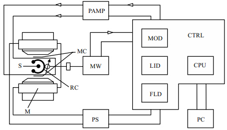
1 Experimental methods 1.1 ESR equipment design featuresFunctionally our ESR spectrometer consists of the following blocks(Fig. 1)[6, 7]: magnet(M), resonant cavity(RC)with modulation coils(MC) and investigated sample(S), microwave unit(MW), power amplifier(PAMP), registration and control unit - controller(CTRL), power supply unit(PS), personal computer(PC).
|
| Fig. 1 ESR spectrometer functional scheme |
The magnet system based on electromagnet or permanent magnet creates a polarizing magnetic field B0. Scanning coils are used to scan the magnetic field over the given range. They are fixed on kerns, symmetrically with respect to the gap of magnet. The control of current in scanning coils is carried out by power supply unit and controller. The investigated sample(S)is located in resonant cavity which is disposed in the gap of a magnet. High-frequency(100 kHz)modulation coils are fastened on side walls of the resonant cavity(TE 102 type) and connected to a power amplifier.
The registration and control unit-controller(CTRL)realizes functions of magnetic field HF modulation control(MOD), lock-in signal detection(LID), magnetic field scan control(FLD), preliminary processing of an ESR signal(CPU). The registration and control unit creates regulated stabilized voltages for power supply of the microwave oscillator and for HF-modulation power amplifier, control signals of a magnetic field scans for magnetic field power supply unit. This unit is working under the control of the microcontroller. Any controls and adjustments required for autonomous detecting and processing of the ESR spectra, are integrated in the registration and control unit. The ESR spectrometer is attached to the personal computer for the access to some service functions.
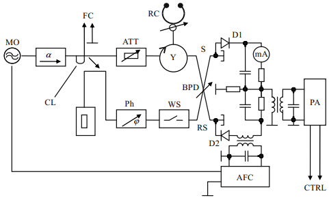
1.2 Microwave unitA microwave unit generates energy of the microwave field passing to the resonant cavity and provides the ESR signal detection. We developed two types of microwave units: homodyne and autodyne ones. The functional scheme of the homodyne type microwave unit is shown in the Fig. 2.
|
| Fig. 2 Homodyne type microwave unit functional scheme |
A microwave Gunn oscillator(MO)generates energy of the microwave field in X-b and (9.0~9.6 GHz). Frequency variation of the microwave oscillator is carried out with special electromechanical arrangement. The microwave oscillator also has an electrical automated frequency control(AFC)system in the range of 30 MHz. The oscillator frequency is stabilized by means of AFC system. The function of an attenuator(ATT)is to control the intensity of the microwave field. A slot bridge, D1 and D2 detectors are used in the balanced phase detector(BPD). The waveguide shunt has a phase shifter(Ph) and a waveguide switch(WS). The phase shift adjustment of microwave reference signal(RS)going to balanced phase detector along with signal(S)from Y-circulator allows to obtain maximum signal/noise ratio(S/N). The function of waveguide switch is to pass or stop the reference signal going to balanced phase detector. The coupling loop(CL)directs the power(1 mW)to the external frequency counter(FC). The microwave unit also comprises a preamplifier(PA) and stabilized power supply.
X-b and ESR spectrometers which use oscillators on a Gunn diode or an avalanche diode placed in a working microwave cavity are called autodyne type ESR spectrometers[8, 9]. They have some advantages in comparison with homodyne and superheterodyne type ESR spectrometers such as a smaller size, simplicity in operation and a long time stability of generation. Q factor of the microwave cavity is not more than 500 in this case and it leads to limitation of ESR spectrometers sensitivity. Furthermore, conditions of microwave generation can be broken after changing the sample because the modification of microwave field distribution in cavity and the change of amplitude of the magnetic microwave field can occur. This circumstance doesn’t allow to get optimum distribution of microwave field in the cavity from the point of view of ESR sensitivity. It should be considered that the change of sample temperature results in a change of the oscillator diode temperature. This alteration leads to a shift of frequency and a change of generated power, therefore it results in the decrease of the measurement accuracy. Thus autodyne ESR spectrometers of this type may be used mainly for teaching process or as ESR analyzer for samples which have the same dielectric properties[8, 9].
We developed and experimentally investigated two-cavities autodyne ESR spectro- meters deprived of these drawbacks. Distinctive feature of these ESR spectrometers is the location of the sample in the working cavity coupled with separate generator cavity where Gunn diode is located. This cavity serves not only as a working cavity but also as a stabilizing cavity. In this case Q factor of working cavity is higher and the frequency and amplitude noises are less, than in the case of only one cavity. It means that higher sensitivity may be reached. Our measurements show that sensitivity of the two-cavities autodyne ESR spectrometer is not worse than 5×10¹¹ spin/(10-4 T), whereas the sensitivity of one cavity autodyne ESR spectrometer is 2×10¹² spin/(10-4 T)[8].
1.3 ESR signal control and recording unitThe ESR signal control and recording unit is a module microprocessor system. The module set of the recording unit depends on the function of an ESR spectrometer and its modifications. Master and interface modules are possible. The processor and graphics adapter modules belong to master modules which are printed-circuit boards. Interface modules are: a digital interface, ESR signal recording module for an autodyne spectrometer, signal recording module for a homodyne spectrometer, temperature control module and magnet system control module. These modules are printed-circuit boards.
1.4 ESR spectrometers magnet systemThe magnet system is based on electromagnet or permanent magnet. These magnets are characterized by small weight and dimensions, high efficiency and simplicity in operation, low dissipation field, no cooling system, high performance. Mathematical simulation and experiments with different magnetic materials allowed to optimize the magnet system construction and technology, to develop unique compact magnet systems for ESR spectrometers.
The simulation of the electromagnet coils temperature field and magnetic field variation is based on solving inhomogeneous equations of heat transfer. The restrictions on dimensions, weight, current strength and number of ampere-turns dictated by desirable induction and homogeneity of magnetic field were considered during simulation. As a result there was developed an optimal electromagnet construction with small dimensions and weight, no cooling system. Theoretical analysis of electromagnet heat conditions permitted to plot nomograms for calculating geometrical dimensions of electromagnet components(coils, kern, yoke), determining the cross section of copper b and , the number of winding sections, electromagnet current and power consumption. Practical electromagnets for ESR spectrometers which are produced in accordance with the calculations show that they are accurate within 5%.
Main electromagnet has the following specifications: scan range of magnetic field induction: 20~600 mT; homogeneity of magnetic field: 10-5(for effective sample volume); stability of magnetic field: 10-5; air gap width: 24 mm; diameter of pole pieces: 100 mm, dimensions: 260×300×320 mm3; weight: 80 kg.
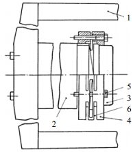
An important element of the electromagnet is special fastening of pole pieces which improves the field homogeneity due to some simple operations. The fastener(see Fig. 3)is made in the form of a clamp nut having a number of through slots and adjusting screws.
|
| Fig. 3 Fastening of electromagnet pole pieces: 1. yoke, 2. kerns, 3. pole pieces, 4. clamp nuts, 5. adjusting screws,6. damper |
The through slots are parallel to the axis of pole pieces and kerns. Three slots whose axes pass across the geometrical center of the nut are homogeneously distributed on the outside surface and are in one plan parallel to nut butts. Kerns are made so that butts turned to the yoke fit it closely on all the butt surface; the butt of one of the kerns turned to the pole piece is a cone with angular vertex of about 179°, while the butt of the other kern is flat. Pole pieces are attached to kerns by clamp nuts made of elastic material. The nut, which fastens the pole piece to the kern having cone-shaped butt has a number of through slots made as described above. It ensures elastic deformation of tension or compression between part of the nut screwed on the kern and part of the clamp nut with the pole piece fixed in it.
The adjustment of field homogeneity in the electromagnet gap is accomplished by rotating adjusting screws placed along the butt surface of the clamp nut so that their axes pass in the middle of slots. The deformation of some parts of a clamp nut controlled by slots and adjusting screws causes fixed position variation of a pole piece relative to the axis passing through the center of pole pieces. Thus, as the mass of a pole piece is several kilograms, i.e. much smaller than one of kerns and coils, the deformation effect on adjusting screws is significantly less. This ensures both simplicity of adjustment and higher time stability of homogeneity of the magnet system.
For various practical ESR applications in industry, medicine, agriculture etc. it is necessary to use compact low weight instrumentation. In some cases there is no necessity to scan magnetic field in wide range. For example, there is a wide class of objects(spin labels, free-radical states, ions of transition metals)whose ESR spectrum research requires the magnetic field scanning over the limited range. In these cases it is reasonable to use magnet system based on permanent magnets from magnetic hard materials; this allows to reduce the power consumption, dimensions and the weight of the magnet system in many times. Production of power supply, stabilization system and magnetic field control unit is thus simplified.
We developed permanent magnets made from various magnetic hard materials which can be magnetized to any induction of the magnetic field over the range of 0.01~1.5 T in the gap of 20~10 mm. These parameters depend on the frequency and the construction of probes employed in ESR spectrometers. The homogeneity of the magnetic field is about 10-5(in volume of 10-6 m3), the weight is not heavier than 30 kg. To produce magnetic field up to 0.2 T ferrites are used as magnetic hard materials, while samarium-cobalt alloys are used to obtain magnetic fields higher than 0.2 T.
The developed permanent magnets include a P- or O-shaped yoke made of a magnetically soft material, kerns of magnetic hard elements with rectangular or circular cross-section and pole pieces(concentrators)of magnetically soft material. Scanning coils are fixed on kerns, symmetrically with respect to the magnet gap. High homogeneity of the magnetic field is accomplished by means of a special system of homogeneity adjustment, by grinding concentrator surfaces and magnetization homogeneity of magnet elements. Temperature and physical characteristics of magnetic hard elements are used to ensure long-term stability and reliability of a magnet system.
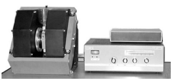
2 Results and applicationsWe developed a new compact ESR equipment[6].The original ESR instrumentation(Fig. 4)consist of electromagnet, ESR cavity(TE 102 type), ESR microwave unit, ESR signal control and recording unit and power supply unit. Maximum ESR ampoule diameter(11 mm)in the microwave cavity of ESR spectrometer allow to use the finger dewar for the nitrogen temperature measurements. We have also developed compact digital temperature control unit for 100~400 K range.
|
| Fig. 4 SCompact ESR equipment |
Specifications of compact ESR equipment are presented in Table 1.
| Parameters | Values |
| ESR sensitivity/(10-4 T) | 2×10¹⁰ spin |
| ESR operating frequency/GHz | 9.0~9.6 |
| Maximum microwave power/W | 0.15 |
| Induction of magnetic field/T | 0.05~0.7 |
| Maximum ESR ampoule diameter/mm | 11 |
Togetherwith the researchers from various scientific centers of Russia and other countries, specialized compact ESR equipment has been successfully tested for solving the following problems[10, 11, 12, 13]:
· investigation of the behavior of paramagnetic ions of transition metals(Mn2+, Fe3+, Cu2+, Cr3+)in aqueous and aqueous-acid matrices in liquid and frozen states;
· determination of photo-oxidizable impurities(metals with variable valence——V2+, Cr2+, Fe2+ and aromatic compounds——benzene, hydro-xenon, oil products)in water solutions;
· determination of isotopic composition, deuterium concentration in natural waters;
· evaluation of traces of non-paramagnetic metals of different groups(Ag, Pb, Cd, Hg, Pb and others)in solutions by the extraction-radiospectroscopic analysis;
· monitoring of spin-labeled waters pumped into oil wells to increase the oil output;
· determination of vanadium(IV) and free radicals contents in oil and oil products;
· control of quantum haemotherapeutics methods such as ultraviolet and laser blood irradiation and millimeter wave irradiation of nonthermal action;
· determination of membrane states and the peculiarities of thrombocyte lipid peroxidation by spin-labeling method for patients with unstable stenocardia;
· investigation of the antioxidant system of blood protection at different forms of stresses(immobilized, infectional, operational);
· control over the antioxidant applications in case of different infections;
· detection of nitric oxide(NO)radicals in animal cells and tissues, specifically in cardio-vascular and central nervous system, alimentary canal, immune and reproductive system;
· study of new spin labels, probes and traps(imidazoline and imidazolidine nitroxides)in molecular biology and medicine(as spin pH-sensitive probes for measurement of local pH-values inside various cells and tissues, as a contrast enhancers in NMR- tomography);
· ecologic monitoring of spin-labeled sewage;
· evaluation of retrospective doses of radiation in ESR-biodosimetry using the measure of ESR signal of dental enamel;
· separation of magnetoanisotropic and isotropic spin interactions by the orientationally modulated EPR method in solids.
Technical features and possibilities of our compact ESR equipment have been tested in the international intercomparison trial on “self-calibrated” ESR dosimeters[13]. Experimental data obtained not only on our instrumentation(model ESR-10-Mini)but also on ESR spectrometers of other manufactures at the same measurement conditions give evidence of high performance of our compact ESR spectrometer.
One of the significantapplications of our compact ESR spectrometer is its usage in the synthetic rubber industry for the ESR control in the technological process of isoprene polymerization catalyst preparation[10].
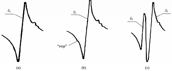
We examined the ESR of the catalyst system {TiCl4 + Al(i-C4H9)3} in the toluene solution, used in the polyisoprene production. The ESR research was carried out under different temperatures, various concentrations and component ratios, some electron-donor compound additions. The results of the ESR investigation show that when TiCl4 and Al(i-C4H9)3 interact in the toluene solution over the temperature range from 20℃ to-80℃ with Al/Ti ratio from 0.5 to 2.0, paramagnetic Ti3+ complexes are generated, that causes two mutually overlapping ESR signals S1 and S2 having the Gaussian line form with the width ΔHpp = 16×10-4 T, the g-factor being g1 = 1.924 and g2 = 1.931 respectively(Fig. 5).
|
| Fig. 5 ESR spectra of three-component catalyst system under -78 ℃:(a)Al/Ti < 1;(b)Al/Ti ≈ 1;(c)Al/Ti > 1 |
The introduction of the electron-donor compound into the catalyst system causes the shift of the S1 signal whose g-factor becomes equal to 1.916, other ESR spectrum parameters are constant. The ESR research both in two-component and three-component catalyst systems under dynamic technological conditions shows that the line intensity S1 and S2 and the resulting ESR spectrum form depend mainly on the component concentration and ratios, the temperature and catalyst preparation time, and the presence of impurities.
With Al/Ti ratio from 0.5 to 0.9, irrespective of the catalyst preparation temperature, in the ESR spectrum there is only signal S1 [Fig. 5(a)]. Intensity of this signal increases with the increase in Al/Ti ratio and has a maximum at Al/Ti = 0.9~1.0. The signal S1 intensity decreases when Al/Ti ratio becomes larger than 1.0. The signal S2 appears at Al/Ti = 0.9~1.0 first as “a step” [Fig. 5(b)] on the intensive signal(S1)wing, then it becomes more resolved [Fig. 5(c)], its intensity is increasing with the increase in the Al/Ti ratio. The intensity increase of the signal S2 is proportional to the intensity decrease of the signal S1. The intensity of signal S2 is maximum when Al/Ti = 1.5~1.6, signal S1 in this case is a small signal.
The line form, g-factors of signals S1 and S2 for Al/Ti = 0.5~2.0 over the temperature range from 20 ℃ to-80 ℃ are invariable, the line width ΔHpp is increased slightly when the temperature is decreased.
The measurements of the catalyst activity show that the maximum catalytic activity occurs at Al/Ti = 0.9~1.0. The interaction of the catalyst under Al/Ti = 1.0 with the monomer- isoprene at 20 ℃ results in the absence of signal S1 and the presence of an intensive signal S3, with the g-factor being equal to 1.948 and the line width ΔHpp = 24×10-4 T. In this case the signal S2 is not observed, because of its overlapping with an intensive signal S3.
Thus, the ESR study for isoprene polymerization catalysts shows the presence of two paramagnetic complexes Ti3+, having different lig and environment. One of these complexes from which the ESR signal S1 arises, is catalytically active.
The obtained dependencies between the variation of ESR spectra parameters and the component ratios, the temperature and the catalyst preparation time, permitted to develop and implement the automated system of the ESR control in the technological process of the isoprene polymerization catalyst production. The described system has been realized under continuous dynamic operating technological conditions in the synthetic rubber industry, it is based on the compact ESR analyzers equipped with a specialized microprocessor system developed by the authors.
Automated ESR analyzers are successfully used from 1979 at six large factories producing synthetic rubber(polyisoprene)in Russia.
3 ConclusionsA new compact ESR equipment was developed both for research and for analytical applications. The instrumentation described can be characterized by low cost, reliability and simplicity, small size and high level of measurement automation, a wide choice of functional modules and units. Various modifications of the presented compact ESR instrumentation are successfully realized which can be used not only in stationary research laboratories but also in mobile clinic and field laboratories as well as in industrial conditions to control continuous technological processes.
Acknowledgement: We thank Dr. C. Jing of Euclid Techlabs LLC, Solon, OH, USA for help in preparing the Chinese part of manuscript.| [1] | [OL] http://www.bruker.com |
| [2] | [OL] http://www.activespectrum.com |
| [3] | [OL] http://www.magnettech.de |
| [4] | [OL] http://www.resonanceinstruments.com |
| [5] | [OL] http://www.adani.by |
| [6] | [OL] http://www.resonance-m.com |
| [7] | Bogachev Yu V, Drapkin V Z, Knyazev M N, et al. Compact problem-oriented EPR equipment. (Rus.)[J]. Izvestia SPbSETU “LETI”, Russia, 2009, 7: 12-22. |
| [8] | Hogg R D. A low cost X-band IMPATT diode marginal oscillator for EPR[J]. Am J Phys, 1973, 41(2): 224-229. |
| [9] | Rupp L W, Walsh W M, Steinfeld A. Simplified microwave frequency electron spin resonance spectrometer[J]. Am J Phys, 1970, 38(2): 238-242. |
| [10] | Bogachev Yu V, Drapkin V Z, Knyazev M N, et al. EPR and ENDOR investigations of isoprene polymerization catalysts. The EPR application in synthetic rubber industry. (Rus.)[J]. Izvestia SPbSETU “LETI”, Russia, 2009, 3: 9-14. |
| [11] | Saakov V S, Drapkin V Z, Krivchenko A I, et al. Derivative Spectrophotometry and Electron Spin Resonance (ESR) Spectroscopy for Ecological and Biological Questions[M]. New York: Springer-Verlag Wien, 2013. |
| [12] | Bogachev Yu V, Drapkin V Z, Knyazev M N, et al. Magnetic Resonance. Basics and Applications (Rus.)[M]. Russia: Saint-Petersburg, SPbSETU “LETI”, 2009. |
| [13] | Gancheva V, Yordanov N D, Callens F, et al. An international intercomparison trial on “self-calibrated” alanine EPR dosimeters[J]. Radiat Phys Chem, 2008, 77(3): 357-364. |
 2016, Vol. 33


