2. 中国科学院大学, 北京 100049
2. University of Chinese Academy of Sciences, Beijing 100049, China
航空磁法测量是磁异常检测的重要方法之一,广泛应用于地球物理和军事领域,尤其在矿产资源勘查和航空反潜中获得成功应用[1-3]。航空磁法测量具有以下优点:
1) 高效:航空磁法测量采用飞机搭载磁力仪实现空间磁场的测量,可以快速实现大面积的勘探作业。
2) 安全:通过机载平台进行空间磁场测量,可以避免人员进入高危区域,降低作业风险。
3) 可靠:相比于地面磁场测量方式,航空磁法测量可以避免地面局部磁异常体及地表噪声的影响,提高数据的可靠性。
在航空磁法测量过程中,设备搭载平台通常是固定翼、直升机、无人机等飞行器。由于搭载平台含有铁磁性材料,在航磁测量时,必然会对飞机搭载的磁力仪产生干扰磁场,影响数据的准确性,因此在进行航空磁法测量时,有效地补偿飞机产生的磁干扰具有重要的意义。
航磁补偿技术起源于二战时期磁异常反潜技术,为提高对潜艇的检测能力,Tolles[4-5]提出航磁补偿模型,将飞机的干扰磁场分成3部分:恒定干扰磁场、感应干扰磁场和涡流干扰磁场,并提出硬补偿方案。其后,Leliak[6]进一步完善航磁补偿模型,针对模型中的复共线性问题,给出正弦机动飞行的方式实现标定飞行,显著地提升了补偿器的补偿效果。随着电子技术的发展,传统的硬补偿方法逐渐发展为软补偿方法,Leach[7]将航磁补偿模型作为最小二乘问题,给出航磁补偿问题的软补偿方法。21世纪,Nelson[8-11]在该领域进行了大量研究,包括补偿后剩余磁场的功率谱分析、地面补偿方法以及飞机噪声源分析等。其后Noriega[12-14]对航磁补偿结果的稳定性进行研究,提出有效评估标定飞行结果的数值方法,引入评估补偿系数泛化能力的交叉标定系数。在国内相关领域,也有众多学者开展相关研究并且有丰富的成果涌现,相关单位主要有中船重工第715研究所、海军工程大学、航遥中心、国防科学技术大学、哈尔滨工业大学、吉林大学、中国科学院遥感应用研究所、中国科学院电子学研究所等[15-25]。
在航磁补偿过程中,飞机首先需要进行标定飞行,在标定飞行时,飞机需要以一定的规范进行机动飞行,由于飞机航速不同,导致飞机机动飞行频率不同,最终每次用于求解补偿系数的频带会相应地发生变化。因此在航磁补偿过程中有必要对补偿系数求解的最优频带进行估计。
本文针对机动飞行导致磁补偿系数求解频带发生变化的问题,提出采用功率谱估计的方法实现最优补偿系数求解频带的估计,结合航磁补偿模型,达到提高补偿效果的目的。该方法成功应用于搭载固定伸杆的直升机航磁勘探系统,并通过野外标定飞行实验验证该方法的有效性。
1 航磁补偿 1.1 航磁补偿模型航磁补偿模型的基本原理是利用三轴磁通门磁力仪测量飞机的姿态,从而补偿光泵总场测量磁力仪受到的干扰磁场。在航磁补偿模型中,通过建立三轴磁通门磁力仪输出和地磁场矢量在飞机载体坐标系中方向余弦的关系实现飞机姿态的测量,二者关系可表示为
| $ \begin{array}{l} {u_1} = \cos X\left( t \right) = T\left( t \right)/\sqrt {T{{\left( t \right)}^2} + L{{\left( t \right)}^2} + V{{\left( t \right)}^2}} \\ {u_2} = \cos Y\left( t \right) = L\left( t \right)/\sqrt {T{{\left( t \right)}^2} + L{{\left( t \right)}^2} + V{{\left( t \right)}^2}} \\ {u_3} = \cos Z\left( t \right) = V\left( t \right)/\sqrt {T{{\left( t \right)}^2} + L{{\left( t \right)}^2} + V{{\left( t \right)}^2}} , \end{array} $ | (1) |
式中:u1、u2和u3是地磁场矢量和飞机载体坐标系3个方向轴正方向夹角的余弦值;T(t)、L(t)和V(t)是三轴磁通门在3个方向上的输出。
航磁补偿模型中光泵探头处受到的飞机磁干扰可以分成以下3类:
1) 恒定干扰磁场:飞机的制作材料中存在永磁性材料,这些材料在光泵磁力仪探头处产生的干扰磁场即是恒定干扰磁场。其表达式为
| $ \begin{array}{l} {H_{{\rm{PERM}}}}\left( t \right) = {c_1}{u_1} + {c_2}{u_2} + {c_3}{u_3}\\ \;\;\;\;\;\;\;\;\;\;\;\;\;\; = {A_1}{c_1} + {A_2}{c_2} + {A_3}{c_3}, \end{array} $ | (2) |
式中:ci, i=1, 2,3为恒定干扰磁场的补偿系数;Ai, i=1, 2, 3为方向余弦组成的特征项。
2) 感应干扰磁场:飞机中的铁磁性材料会受到地磁场的磁化,产生的磁化磁场在光泵磁力仪探头处产生的干扰磁场即是感应干扰磁场,其表达式为
| $ \begin{array}{l} {H_{{\rm{IND}}}}\left( t \right) = {H_{\rm{e}}}\left( t \right)\left( \begin{array}{l} {c_4}u_1^2 + {c_5}{u_1}{u_2} + {c_6}{u_1}{u_3}\\ + {c_7}u_2^2 + {c_8}{u_2}{u_3} + {c_9}u_3^2 \end{array} \right)\\ \;\;\;\;\;\;\;\;\;\;\;\; = {A_4}{c_4} + {A_5}{c_5} + {A_6}{c_6} + {A_7}{c_7} + {A_8}{c_8} + {A_9}{c_9}, \end{array} $ | (3) |
式中:He(t)为地磁场的大小;ci, i=4, …, 9为感应干扰磁场的补偿系数;Ai, i=4, …, 9为对应的方向余弦和He(t)组成的特征项。
3) 涡流干扰磁场:飞机在地磁场中做切割地磁场磁力线运动时,飞机的金属蒙皮等金属部件会感生涡旋电流,该涡旋电流会进一步产生感生磁场,进而对光泵探头处产生干扰磁场,其表达式为
| $ \begin{array}{l} {H_{{\rm{EDDY}}}}\left( t \right) = {H_{\rm{e}}}\left( t \right)\left( \begin{array}{l} {c_{10}}{u_1}{{u'}_1} + {c_{11}}{u_1}{{u'}_2} + {c_{12}}{u_1}{{u'}_3} + \\ {c_{13}}{u_2}{{u'}_1} + {c_{14}}{u_2}{{u'}_2} + {c_{15}}{u_2}{{u'}_3} + \\ {c_{16}}{u_3}{{u'}_1} + {c_{17}}{u_3}{{u'}_2} + {c_{18}}{u_3}{{u'}_3} \end{array} \right)\\ \;\;\;\;\;\;\;\;\;\;\;\;\;\; = {A_{10}}{c_{10}} + {A_{11}}{c_{11}} + {A_{12}}{c_{12}} + {A_{13}}{c_{13}} + \\ \;\;\;\;\;\;\;{A_{14}}{c_{14}} + {A_{15}}{c_{15}} + {A_{16}}{c_{16}} + {A_{17}}{c_{17}} + {A_{18}}{c_{18}}, \end{array} $ | (4) |
式中:u′1、u′2和u′3分别为u1、u2和u3对时间的导数;ci, i=10, …, 18为恒定干扰磁场的补偿系数;Ai, i=10, …, 18为对应的方向余弦和He(t)组成的特征项。
飞机在光泵探头处的干扰磁场可以表示为
| $ \begin{array}{l} {H_{\rm{d}}}\left( t \right) = {H_{{\rm{PERM}}}}\left( t \right) + {H_{{\rm{IND}}}}\left( t \right) + {H_{{\rm{EDDY}}}}\left( t \right)\\ \;\;\;\;\;\;\;\;\; = \sum\limits_{i = 1}^{18} {{A_i}{c_i}} . \end{array} $ | (5) |
对应的矩阵表达式可以表示为
| $ {\mathit{\boldsymbol{H}}_{\rm{d}}} = \mathit{\boldsymbol{AC}} + \mathit{\boldsymbol{z}}, $ | (6) |
式中:飞机干扰磁场Hd为Hd(t)的离散时间序列组成的列向量,其表达式为Hd=[Hd(1) Hd(2) … Hd(n)]T;C为补偿系数ci, i=1, …, 18组成的列向量,其表达式为C=[c1 c2 … c18]T;A为对应的特征项的离散时间序列,可以表示为
式(6)中补偿系数的最小二乘解可以表示为
| $ \mathit{\boldsymbol{C}} = {\left( {{\mathit{\boldsymbol{A}}^{\rm{T}}}\mathit{\boldsymbol{A}}} \right)^{ - 1}}{\mathit{\boldsymbol{A}}^{\rm{T}}}{\mathit{\boldsymbol{H}}_{\rm{d}}}. $ | (7) |
由于航磁补偿模型中存在一定程度的复共线性,因此采用岭回归算法来实现补偿系数C的求解,将提升补偿参数求解的准确性,其表达式为
| $ {\mathit{\boldsymbol{C}}_k} = {\left( {{\mathit{\boldsymbol{A}}^{\rm{T}}}\mathit{\boldsymbol{A}} + k\mathit{\boldsymbol{I}}} \right)^{ - 1}}{\mathit{\boldsymbol{A}}^{\rm{T}}}{\mathit{\boldsymbol{H}}_{\rm{d}}}. $ | (8) |
通过标定飞行获取的数据求取补偿系数Ck,进而对飞机的干扰磁场实现补偿,其中补偿系数Ck作用于飞机机动飞行存在的频带。在标准标定飞行过程中,由于在不同频带上机动飞行引起的干扰磁场强度不同,而与机动飞行不相关的噪声却大致相同,因此计算获得的补偿系数Ck跟飞机的机动飞行相关,不同的频带会影响补偿系数Ck计算的准确性。在求解补偿参数之前,需要先预估机动飞行的频率范围,从而获取最优的补偿系数求解频带。
1.2 航磁补偿模型频带估计航磁补偿模型中地磁场矢量在飞机载体坐标系的方向角的余弦cosX(t),cosY(t)和cosZ(t)会随着飞机机动飞行的动作发生周期性的变化。为了方便书写,将3个方向角的余弦简记为cosX,cosY和cosZ,因此可以将3个方向角的余弦假定为下式:
| $ \begin{array}{*{20}{c}} {\cos X = {d_1} + {k_1}\sin \left( {2{\rm{ \mathsf{ π} }}ft + {\theta _1}} \right)}\\ {\cos Y = {d_2} + {k_2}\sin \left( {2{\rm{ \mathsf{ π} }}ft + {\theta _2}} \right)}\\ {\cos Z = {d_3} + {k_3}\sin \left( {2{\rm{ \mathsf{ π} }}ft + {\theta _3}} \right)} \end{array}, $ | (9) |
式中:d1,d2和d3分别为常数项;k1,k2和k3为方向角的变化幅度;θ1,θ2和θ3为姿态角间的相差;f为飞机的机动频率。
式(3)感应干扰磁场可以变化为
| $ {H_{{\rm{IND}}}} = {H_e}\left( \begin{array}{l} {c_4}\left( \begin{array}{l} d_1^2 + \frac{1}{2}k_1^2 + 2{d_1}{k_1}\sin \left( {2{\rm{ \mathsf{ π} }}ft + {\theta _1}} \right) - \\ \frac{1}{2}k_1^2\cos \left( {4{\rm{ \mathsf{ π} }}ft + 2{\theta _1}} \right) \end{array} \right) + \\ {c_5}\left( \begin{array}{l} {d_1}{d_2} + {d_1}{k_2}\sin \left( {2{\rm{ \mathsf{ π} }}f + {\theta _2}} \right) + \\ {d_2}{k_1}\sin \left( {2{\rm{ \mathsf{ π} }}ft + {\theta _1}} \right) - \\ \frac{1}{2}{k_1}{k_2}\left( \begin{array}{l} \cos \left( {4{\rm{ \mathsf{ π} }}ft + {\theta _1} + {\theta _2}} \right) - \\ \cos \left( {{\theta _1} - {\theta _2}} \right) \end{array} \right) \end{array} \right) + \\ {c_6}\left( \begin{array}{l} {d_1}{d_3} + {d_1}{k_3}\sin \left( {2{\rm{ \mathsf{ π} }}f + {\theta _3}} \right) + \\ {d_3}{k_1}\sin \left( {2{\rm{ \mathsf{ π} }}ft + {\theta _1}} \right) - \\ \frac{1}{2}{k_1}{k_3}\left( \begin{array}{l} \cos \left( {4{\rm{ \mathsf{ π} }}ft + {\theta _1} + {\theta _3}} \right) - \\ \cos \left( {{\theta _1} - {\theta _3}} \right) \end{array} \right) \end{array} \right)\\ + {c_7}\left( \begin{array}{l} d_2^2 + \frac{1}{2}k_2^2 + 2{d_2}{k_2}\sin \left( {2{\rm{ \mathsf{ π} }}ft + {\theta _2}} \right) - \\ \frac{1}{2}k_2^2\cos \left( {4{\rm{ \mathsf{ π} }}ft + 2{\theta _2}} \right) \end{array} \right)\\ {c_8}\left( \begin{array}{l} {d_2}{d_3} + {d_2}{k_3}\sin \left( {2{\rm{ \mathsf{ π} }}f + {\theta _3}} \right) + \\ {d_3}{k_2}\sin \left( {2{\rm{ \mathsf{ π} }}ft + {\theta _2}} \right) - \\ \frac{1}{2}{k_2}{k_3}\left( \begin{array}{l} \cos \left( {4{\rm{ \mathsf{ π} }}ft + {\theta _2} + {\theta _3}} \right) - \\ \cos \left( {{\theta _2} - {\theta _3}} \right) \end{array} \right) \end{array} \right) + \\ {c_9}\left( \begin{array}{l} d_3^2 + \frac{1}{2}k_3^2 + 2{d_3}{k_3}\sin \left( {2{\rm{ \mathsf{ π} }}ft + {\theta _3}} \right) - \\ \frac{1}{2}k_3^2\cos \left( {4{\rm{ \mathsf{ π} }}ft + 2{\theta _3}} \right) \end{array} \right) \end{array} \right). $ | (10) |
式(4)涡流干扰磁场可以变化为
| $ {H_{{\rm{EDDY}}}} = {H_{e}}{\rm{ \mathsf{ π} }}f\left( \begin{array}{l} {c_{10}}{k_1}\left( \begin{array}{l} 2{d_1}\cos \left( {2{\rm{ \mathsf{ π} }}ft + {\theta _1}} \right) + \\ {k_1}\sin \left( {4{\rm{ \mathsf{ π} }}ft + 2{\theta _1}} \right) \end{array} \right) + \\ {c_{11}}{k_2}\left( \begin{array}{l} 2{d_1}\cos \left( {2{\rm{ \mathsf{ π} }}ft + {\theta _2}} \right) + \\ {k_1}\left( \begin{array}{l} \sin \left( {4{\rm{ \mathsf{ π} }}ft + {\theta _1} + {\theta _2}} \right) + \\ \sin \left( {{\theta _1} - {\theta _2}} \right) \end{array} \right) \end{array} \right) + \\ {c_{12}}{k_3}\left( \begin{array}{l} 2{d_1}\cos \left( {2{\rm{ \mathsf{ π} }}ft + {\theta _3}} \right) + \\ {k_1}\left( \begin{array}{l} \sin \left( {4{\rm{ \mathsf{ π} }}ft + {\theta _1} + {\theta _3}} \right) + \\ \sin \left( {{\theta _1} - {\theta _3}} \right) \end{array} \right) \end{array} \right) + \\ {c_{13}}{k_1}\left( \begin{array}{l} 2{d_2}\cos \left( {2{\rm{ \mathsf{ π} }}ft + {\theta _1}} \right) + \\ {k_2}\left( \begin{array}{l} \sin \left( {4{\rm{ \mathsf{ π} }}ft + {\theta _2} + {\theta _1}} \right) + \\ \sin \left( {{\theta _2} - {\theta _1}} \right) \end{array} \right) \end{array} \right) + \\ {c_{14}}{k_2}\left( \begin{array}{l} 2{d_2}\cos \left( {2{\rm{ \mathsf{ π} }}ft + {\theta _2}} \right) + \\ {k_2}\sin \left( {4{\rm{ \mathsf{ π} }}ft + 2{\theta _2}} \right) \end{array} \right) + \\ {c_{15}}{k_3}\left( \begin{array}{l} 2{d_2}\cos \left( {2{\rm{ \mathsf{ π} }}ft + {\theta _3}} \right) + \\ {k_2}\left( \begin{array}{l} \sin \left( {4{\rm{ \mathsf{ π} }}ft + {\theta _2} + {\theta _3}} \right) + \\ \sin \left( {{\theta _2} - {\theta _3}} \right) \end{array} \right) \end{array} \right) + \\ {c_{16}}{k_1}\left( \begin{array}{l} 2{d_3}\cos \left( {2{\rm{ \mathsf{ π} }}ft + {\theta _1}} \right) + \\ {k_3}\left( \begin{array}{l} \sin \left( {4{\rm{ \mathsf{ π} }}ft + {\theta _3} + {\theta _1}} \right) + \\ \sin \left( {{\theta _3} - {\theta _1}} \right) \end{array} \right) \end{array} \right) + \\ {c_{17}}{k_2}\left( \begin{array}{l} 2{d_3}\cos \left( {2{\rm{ \mathsf{ π} }}ft + {\theta _2}} \right) + \\ {k_3}\left( \begin{array}{l} \sin \left( {4{\rm{ \mathsf{ π} }}ft + {\theta _3} + {\theta _2}} \right) + \\ \sin \left( {{\theta _3} - {\theta _2}} \right) \end{array} \right) \end{array} \right) + \\ {c_{18}}{k_3}\left( \begin{array}{l} 2{d_3}\cos \left( {2{\rm{ \mathsf{ π} }}ft + {\theta _3}} \right) + \\ {k_3}\sin \left( {4{\rm{ \mathsf{ π} }}ft + 2{\theta _3}} \right) \end{array} \right) \end{array} \right). $ | (11) |
将式(2),式(10)和式(11)代入式(5)中,可知飞机干扰磁场的频率分量包含方向余弦cosX,cosY和cosZ的基频f和其二次谐频2f。因此为了获得最优的补偿频带,从而有效地求取磁干扰补偿系数,需要对地磁场矢量在飞机载体坐标系中的方向余弦进行频谱分析。本文采用功率谱估计的方法来实现最优补偿系数求解频带的估计。
2 功率谱估计功率谱估计可以获得信号的功率谱密度,用来实现对信号各频率成分的估计[26]。常见的功率谱估计方法可以分为非参数功率谱估计和参数功率谱估计,针对不同类型的信号,不同的方法效果有所不同。
2.1 Welch功率谱估计Welch法属于非参数谱估计方法,其特点在于两个方面:1)允许子序列xi(n)相互叠加;2)对各子序列可以进行加窗处理,产生的是平均的修正周期图。
假设相邻的子序列偏移D个点,各子序列长度为L,则第i个序列是
| $ {x_i}\left( n \right) = x\left( {n + iD} \right),n = 0,1, \cdots ,L - 1, $ | (12) |
其中xi(n)和xi+1(n)的重叠(L-D)个点,若整个样本点由K个子序列覆盖,则样本点长度N和K的关系可表示为
| $ N = L + D\left( {K - 1} \right). $ | (13) |
在使用Welch功率谱估计时,为改善旁瓣较大导致的谱失真,对子序列信号进行加窗处理,窗函数为w(n),信号x(n)的Welch谱估计可表达为
| $ {{\hat P}_{xx1}}\left( {{{\rm{e}}^{{\rm{j}}\omega }}} \right) = \frac{1}{{KL}}\sum\limits_{i = 0}^{K - 1} {{{\left| {\sum\limits_{n = 0}^{L - 1} {w\left( n \right)x\left( {n + iD} \right){{\rm{e}}^{ - {\rm{j}}n\omega }}} } \right|}^2}} . $ | (14) |
Welch谱估计是功率谱的渐进无偏估计。
2.2 AR模型功率谱估计AR模型功率谱估计属于参数化的功率谱估计方法,该方法假定信号是一个均方误差为σ2的高斯白噪声序列u(n)激励一个线性时不变系统H(z)所得到的。该系统H(z)即是对应的AR模型。输入信号u(n)和分析信号x(n)间关系满足
| $ x\left( n \right) + \sum\limits_{k = 1}^p {{a_k}x\left( {n - k} \right)} = u\left( n \right), $ | (15) |
所分析信号x(n)的功率谱估计为
| $ {{\hat P}_{xx2}}\left( {{{\rm{e}}^{{\rm{j}}\omega }}} \right) = {\sigma ^2}{\left| {H\left( z \right)} \right|^2}\left| {_{z = {{\rm{e}}^{{\rm{j}}\omega }}}} \right., $ | (16) |
其中H(z)的表达式为
| $ H\left( z \right) = \frac{1}{{1 + \sum\limits_{k = 1}^p {{a_k}{z^{ - k}}} }}. $ | (17) |
航磁补偿中通过功率谱估计能有效地获得飞机干扰场频带,进而获得最优的补偿系数Ck。下面采用两种不同的功率谱估计方法实现最优补偿系数求解频带的估计,并实现飞机干扰磁场的补偿和补偿质量评估。
3 野外飞行实验 3.1 飞行实验设计航磁补偿实验采用直升机搭载固定伸杆来实现,搭载固定伸杆的直升机在3 000 m高空进行标定飞行,完成标定飞行后,直升机进一步完成验证飞行,以便对数据的质量进行评估。搭载设备的直升机见图 1(a)所示, GPS记录的飞行航迹如图 1(b)所示。

|
Download:
|
| 图 1 野外直升机飞行实验 Fig. 1 Helicopter experiment | |
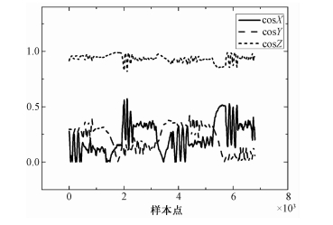
通过与飞机固联的三轴磁通门实现飞机姿态的测量,进而获得地磁场矢量在飞机载体坐标系中的方向余弦,在飞机机动飞行过程中,该方向余弦与飞机机动保持一致的变化,因此采用该方向余弦作为谱估计的对象能获得飞机机动飞行的频带范围。图 2为磁通门的输出计算得到的方向余弦信号。

|
Download:
|
| 图 2 地磁场在载体坐标系中的方向余弦 Fig. 2 Direction cosine of the geomagnetic field in aircraft coordinate system | |
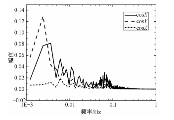
直接傅里叶变换后信号频域的结果见图 3所示。

|
Download:
|
| 图 3 方向余弦的FFT Fig. 3 FFT of direction cosine | |
从图 3可见,直接对信号做傅里叶变换,虽然飞机的机动频率也以尖峰的形式出现在频谱上,但是由于傅里叶变换结果中存在较多的尖峰,在没有任何先验知识的情况下,难以分辨出哪个尖峰对应飞机的机动频率,因此直接FFT变换难以正确区分最优补偿系数求解频带。
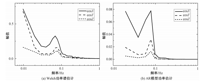
Welch功率谱估计的结果见图 4(a)所示;AR模型功率谱估计的结果见图 4(b)所示。

|
Download:
|
| 图 4 方向余弦功率谱估计 Fig. 4 Power spectrum estimation of direction cosine | |
从图 4(a)和图 4(b)可见,方向余弦的基频的最大值不超过0.1 Hz(峰值点位于0.078 Hz),因此二次谐频不超过0.2 Hz,可见Welch功率谱估计和AR模型功率谱估计均可以很好地将最优补偿系数求解频带提取出来,两种不同的方法具有高度的一致性,结果可互相验证。
3.3 航磁补偿质量评估在飞机干扰磁场补偿过程中,采用包含最优补偿系数求解频带和不包含最优补偿系数求解频带的两种不同的高通滤波器对数据进行预处理,并比较最终补偿效果。其中包含最优补偿系数求解频带的滤波器的通带应该低于方向余弦的基频,因此选用截止频率为0.065 Hz的高通滤波器;不包含最优补偿系数求解频带的滤波器的通带应该高于二次谐频,因此选用截止频率为0.22 Hz的高通滤波器。采用式(8)从标定飞行中获得飞机磁干扰补偿系数,并实现对标定飞行的补偿。补偿结果如图 5所示。其中图 5(a)和图 5(b)为截止频率为0.065 Hz的高通滤波器预处理后再进行补偿的结果;图 5(c)和图 5(d)为截止频率为0.22 Hz的高通滤波器预处理后再进行补偿的结果。

|
Download:
|
| 图 5 不同截止频率滤波器预处理后补偿结果 Fig. 5 Compensation results of filters with different cut-off frequencies | |
图 5采用双纵轴显示,虚线为补偿前的飞机干扰磁场,对应左纵轴;实线为补偿后的剩余磁场对应右纵轴。可见两种不同截止带宽的滤波器均可以对飞机干扰磁场实现较好的预处理,直观上难以直接分辨哪种滤波器处理后的补偿结果最优,因此采用定量的方式对补偿结果进行评估。
航磁补偿中的评估准则采用补偿提升比IR,其表达式为
| $ {\rm{IR}} = \frac{{{\sigma _{\rm{u}}}}}{{{\sigma _{\rm{c}}}}}, $ | (18) |
式中:σu为补偿前信号的标准差,σc为补偿后信号的标准差。两种不同截止频率的滤波器处理后的补偿信号的提升比见表 1所示。其中滤波器1为截止频率为0.065 Hz的滤波器,滤波器2为截止频率为0.22 Hz的滤波器。
|
|
表 1 标准差与补偿提升比 Table 1 Standard deviation and IR |
表中前3行为标定飞行数据结果,后3行为验证飞行数据结果。可见采用截止频率为0.065 Hz的高通滤波器处理后获得最优补偿系数再进行补偿,对于标定飞行和验证飞行均可以获得更好的补偿效果。
4 结论本文提出采用功率谱估计的方法对航磁补偿最优补偿系数求解频带进行估计,并设计标定飞行实验,对航磁补偿结果进行验证。实验结果表明,参数化谱估计和非参数化谱估计对飞机机动飞行频率的估计均优于傅里叶变换。在航磁补偿数据预处理阶段,采用功率谱估计获得最优补偿系数求解频带后计算得到的最优补偿系数,能有效地提高航磁补偿的补偿提升比。
| [1] |
Nabighian M N. The historical development of the magnetic method in exploration[J]. Geophysics, 2005, 70(6): 33-61. DOI:10.1190/1.2133784 |
| [2] |
Hood P. History of aeromagnetic surveying in Canada[J]. Leading Edge, 2012, 26(11): 1384-1392. |
| [3] |
Doll W E, Gamey T J, Bell D T, et al. Historical development and performance of airborne magnetic and electromagnetic systems for mapping and detection of unexploded ordnance[J]. Journal of Environmental & Engineering Geophysics, 2012, 17(1): 1-17. |
| [4] |
Tolles W E. Compensation of aircraft magnetic fields: US 2692970 A[P/OL]. 1954-10-26[2017-07-05]. http://www.freepatentsonline.com/2692970.pdf.
|
| [5] |
Tolles W E. Magnetic field compensation system: US 2706801 A[P/OL]. 1955-04-19[2017-07-05]. http://www.freepatentsonline.com/2706801.pdf.
|
| [6] |
Leliak P. Identification and evaluation of magnetic-field sources of magnetic airborne detector equipped aircraft[J]. Aerospace & Navigational Electronics Ire Transactions on, 1961, ANE-8(3): 95-105. |
| [7] |
Leach B W. Aeromagnetic compensation as a linear regression problem[J]. Information Linkage Between Applied Mathematics & Industry, 2010, 139-161. |
| [8] |
Nelson J B. Aeromagnetic noise during low-altitude flights Over the scotian shelf: DRDC-ATLANTIC-TM-2002-089[R]. Dartmouth NS: Defence Research & Development Canada Atlantic, 2002, 1-40. https://www.researchgate.net/publication/264874391_Aeromagnetic_Noise_During_Low-Altitude_Flights_Over_the_Scotian_Shelf
|
| [9] |
Nelson J B. Predicting in-flight MAD noise from ground measurements: DREA-TM-2001-112[R]. Dartmouth NS: Defence Research Establishment Atlantic, 2002, 1-26. http://pubs.rddc.gc.ca/BASIS/pcandid/www/engpub/DDW?W%3DSYSNUM=518407
|
| [10] |
Nelson J B. Aeromagnetic noise from magnetometers and data acquisition systems[C/OL]//8th International Congress of the Brazilian Geophysical Society(2003-09-14)[2017-07-05]. http://www.earthdoc.org/publication/publicationdetails/?publication=41507.
|
| [11] |
Nelson J B. Aircraft magnetic noise sources[C/OL]//8th International Congress of the Brazilian Geophysical Society, (2003-09-14)[2017-07-05]. http://www.earthdoc.org/publication/publicationdetails/?publication=41506.
|
| [12] |
Noriega G. Aeromagnetic compensation in gradiometry:performance, model stability, and robustness[J]. IEEE Geoscience & Remote Sensing Letters, 2015, 12(1): 117-121. |
| [13] |
Noriega G. Performance measures in aeromagnetic compensation[J]. Leading Edge, 2011, 30(10): 1122-1127. DOI:10.1190/1.3657070 |
| [14] |
Noriega G. Model stability and robustness in aeromagnetic compensation[J]. First Break, 2013, 31(3): 73-79. |
| [15] |
王景然, 卢立波, 刘浩, 等. 贝尔直升机航磁仪磁补偿结果分析[J]. 海洋测绘, 2013, 33(6): 11-13. |
| [16] |
庞学亮, 张宁, 林春生. 基于有限脉冲响应模型的飞机磁场补偿方法[J]. 振动、测试与诊断, 2009, 29(4): 462-465. DOI:10.3969/j.issn.1004-6801.2009.04.020 |
| [17] |
刘首善, 唐林牧, 许庆丰, 等. 航磁补偿技术及补偿质量的评价方法[J]. 海军航空工程学院学报, 2016, 31(6): 641-647. |
| [18] |
骆遥, 段树岭, 王金龙, 等. AGS-863航磁全轴梯度勘查系统关键性指标测试[J]. 物探与化探, 2011, 35(5): 620-625. |
| [19] |
李季, 潘孟春, 罗诗途, 等. 半参数模型在载体干扰磁场补偿中的应用研究[J]. 仪器仪表学报, 2013, 34(9): 2147-2152. |
| [20] |
Dou Z J, Han Q, Niu X M, et al. An aeromagnetic compensation coefficient-estimating method robust to geomagnetic gradient[J]. IEEE Geoscience & Remote Sensing Letters, 2016, 13(5): 611-615. |
| [21] |
Dou Z J, Han Q, Niu X M, et al. An adaptive filter for aeromagnetic compensation based on wavelet multiresolution analysis[J]. IEEE Geoscience & Remote Sensing Letters, 2016, 13(8): 1069-1073. |
| [22] |
Zhang D L, Huang D N, Lu J W, et al. Aeromagnetic compensation with partial least square regression[C/OL]//25th Geophysical Conference & Exhibition Adelaide: Australian Society of Exploration Geophysicists, (2016-08-21)[2017-07-05]. http://www.publish.csiro.au/ex/pdf/ASEG2016ab300.
|
| [23] |
Guo C H, Ma M, Cheng D F. A new solution of aircraft magnetic interference field based on errors-in-variables method[J]. Journal of Computational Intelligence & Electronic Systems, 2015, 4(1): 70-73. |
| [24] |
王婕, 郭子祺, 刘建英. 固定翼无人机航磁探测系统的磁补偿模型分析[J]. 航空学报, 2016, 37(11): 3435-3443. |
| [25] |
Wu P L, Zhang Q Y, Fei C C, et al. Aeromagnetic gradient compensation method for helicopter based on ∈-support vector regression algorithm[J]. Journal of Applied Remote Sensing, 2017, 11(2): 025012. DOI:10.1117/1.JRS.11.025012 |
| [26] |
乐贵明, 叶宗海, 龚菊红. 2001年11月24日特大磁暴前银河宇宙线短时间尺度功率谱分析[J]. 中国科学院研究生院学报, 2002, 19(2): 163-167. DOI:10.3969/j.issn.1002-1175.2002.02.011 |
 2018, Vol. 35


