Global buckling always causes stress-strain accumulation in the pipeline with the increase in temperature, which may jeopardize the structural integrity and cause pipeline failure (DNV, 2012). Therefore, global buckling is a key aspect that is frequently considered in subsea pipeline designs (Wang and Tang, 2020). The options for pipeline buckling control and mitigation can be divided into two categories. The first category prohibits the occurrence of pipeline global buckling with design schemes, including reducing the design temperature and pressure on pipelines and increasing the flexural stiffness of the pipeline and soil resistance to the pipeline. The second category initiates a controlled buckling response in preset locations of pipelines by design schemes, including introducing artificial imperfections and reducing local soil resistance in the pipeline during installation (Bruton et al., 2003).
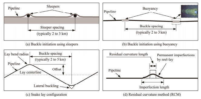
The design scheme of 'prohibit buckling' is always adopted for pipelines in the shallow sea. By contrast, 'initiate controlled buckling' was recommended for pipelines in the deep sea by SAFEBUCK projects (Bruton and Carr, 2005) because a remarkably sophisticated and cost-effective solution is to work with instead of working against the pipeline by controlling the formation of lateral buckles along the pipeline. Buckling initiation techniques, including sleepers (Wang and Jukes, 2008; Sinclair et al., 2009), distributed buoyancy (Thompson et al., 2009; Li et al., 2016; Wang et al., 2018), snake lay (Matheson et al., 2004; Peek et al., 2004; Luo et al., 2013), and residual curvature method (RCM) (Teigen and Ibrahim, 2015, 2017), have been widely applied in engineering and studied by scholars in the last 20 years. The configurations of these typical buckling initiation devices and methods are shown in Fig. 1.
|
Fig. 1 Typical buckling initiation device and methods. |
As shown in Fig. 1, the spacing of trigger devices/configurations (snake lay bend and permanent imperfections by reel-lay) is typically 2 - 5 km. The pipeline segment between two adjacent buckles possibly becomes a short pipeline with the successful initiation of global buckling in most trigger devices/configurations (Carr et al., 2008). Pipeline walking may occur for these short pipeline segments when a pipeline is subjected to tension from the steel catenary riser (SCR), global seabed slope along the pipeline length, or thermal gradient along the pipeline (Bruton et al., 2003, 2010; Rong et al., 2009). Thus, a pipeline, which is designed to buckle laterally, may laterally and axially displace over time when subjected to repeated heating and cooling cycles.
Studies on the coupling interaction of pipeline buckling and walking are limited. In 2003, Bruton first conducted a study on the coupling response of global buckling and walking by pipeline with free ends measuring 12 in. in diameter and 5 km in length. The study claimed that pipeline walking would cause asymmetrical development of its global buckling configuration. Depending on changes in local seabed slopes, a combination of pipeline walking drivers and global buckling was investigated by Cumming et al. (2009). Through response analysis along the pipeline route, Cumming divided the effects of axial movement on pipeline buckling during heating and cooling cycles into the following three categories: experiencing decreasing axial feed-in (givers), maintaining the buckle shape with minimal changes in axial feed-in (stayers), and accumulating the axial feed-in (collectors). Based on the nonlinear finite element simulation results, the lateral buckling and pressure circulation in the pipeline will promote the axial movement of pipelines, as described by Zhou et al. (2010). A strong walking tendency due to the buckle has been identified by Solano et al. (2014) for long pipelines, which have a low tendency to walk. The effects of the number of buckling along a short pipeline on walking rate were evaluated as a controlled walking strategy by Seyfipour et al.(2019, 2021). The study shows that setting more buckling than traditional along a short pipeline with a relatively small VAS can alleviate pipeline walking.
Research on the coupling deformation of pipeline buckling and walking is not only limited in number till now but also in guidance capability to pipeline safety design in engineering. According to the classical research and engineering application (Carneiro et al., 2009), the design principle of the buckling mitigation method, which aims to in-itiate controlled buckling, can be summarized as two points. First, global buckling at most preset pipeline locations, wherein the critical axial force required for buckling initiation must be sufficiently low, should be successfully triggered. Second, the maximum stress and strain of the pipeline in post-buckling should be controlled in the allowable range; that is, the limit state of the pipeline buckling should conform to the design specification. Owing to the two principles, the influence analysis of walking on pipeline buckling should focus on the effect of walking on the capacity of buckling initiation (critical axial force required for buckling) and the influence on the integrity and failure probability of the pipeline post-buckling. However, the above-mentioned existing studies mostly focused on the influence of pipeline walking on the buckling deformation mode. Investigations on the effect of walking on the capacity of buckling initiation and the integrity and failure probability of the pipeline post-buckling are unavailable.
The monitoring data of submarine pipelines in some projects show that pipeline walking per kilometer can reach several centimeters in one opening and closing cycle, and the total cumulative displacement is several meters for a typical design life (Tørnes et al., 2000). The existing studies on pipeline walking are mostly focused on short pipelines (Liu et al., 2020; Hong et al., 2021). However, multiple global buckles along a long pipeline will facilitate division into multiple short pipeline segments. The walking of each short pipeline during heating and cooling cycles will cause cumulative displacement along the long pipeline. The accumulation of axial displacement may induce the failure of submarine pipelines in the form of excessive structural stress and loss of prestress in SCRs, which seriously threatens the safety of the end connection of pipelines (Perinet and Simon, 2011). Therefore, the key to the influence analysis of global buckling on pipeline walking is to establish a calculation method for the walking of a short pipeline segment. However, existing research on the coupling deformation of pipeline buckling and walking only indicates that global buckling may induce pipeline walking, with no research aimed at estimating the walking of pipeline segments between two adjacent buckles.
Submarine pipelines to explore and exploit oil and gas resources in the deep sea are increasingly required to satisfy the 'deep-shallow-land' development model, which inevitably lays considerable long-distance pipelines on the seabed with a definite slope. Thus, a calculation method of the axial movement of a buckling pipeline is proposed with a pipeline on a sloping seabed. Subsequently, the coupling mechanism of lateral buckling and pipeline walking is studied with the influence law of axial movement on global lateral buckling.
2 FE Model to Simulate the Coupling Deformation of Pipeline Buckling and Walking 2.1 FE ModelLiu et al. (2014) proposed a 3D explicit method based on ABAQUS to simulate the global buckling of pipelines. This method was applied to pipeline buckling analysis in many concepts by Liu et al., including the calculation of the perfect VAS length (Liu et al., 2016), lateral buckling based on the model of nonlinear pipe-soil interaction (Liu and Wang, 2018), and critical length calculation of buckling pipelines (Liu and Li, 2018). These applications further increase the applicability of the 3D explicit method in the simulation of global buckling in pipelines. Li and Liu (2020) recently improved the method and applied it to the multiple buckling simulation of a pipeline with more than one initial imperfection, which detailed the method to introduce double imperfections into the FEA model. The coupling deformation simulation of pipeline buckling and walking is also related to submarine pipelines involving multiple imperfections. Thus, the improved 3D explicit method is used in this study.
The improved 3D explicit method can be briefly described as follows. The beam element with element-type PIPE 31 is used to model the pipeline. The constitutive model of the pipeline is the linear elastic model, where the material properties include the pipeline density, outside diameter and wall thickness of the pipeline, elastic modulus, Poisson ratio, and thermal expansion coefficient. The boundary conditions of the pipeline are free on both ends. The average element size of the pipeline is 1 m. The initial imperfections of pipelines are introduced into the pipeline model by the 'import sketch' step in ABAQUS. The form of a single initial imperfection among these multiple pipeline imperfections is calculated by the 'buckle' step in ABAQUS. The C3D8R solid element is used to model the seabed. The constitutive model of the soil is the Mohr-Coulomb model, where the material properties of the soil include the effective density, elastic modulus, Poisson ratio, cohesion, and internal friction angle of soil. The element size of the soil is 1 m. The boundary conditions around the seabed are laterally and axially constrained, and the omnidirectional freedom is constrained at the bottom of the seabed. Hard contact between pipeline and soil in the vertical direction is applied to simulate the interaction between pipeline and seabed, whereas the lateral interaction is simulated by the penalty function. This condition implies that the lateral resistance is governed by the friction coefficient and submerged weight of the pipeline.
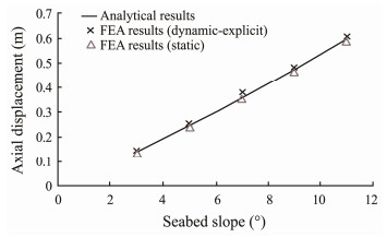
A total of 11 steps are considered to simulate the coupling deformation of pipeline buckling and walking. The first step is to apply the gravity field to ensure a hard contact between the pipeline and the soil. The second step is to increase the temperature of the pipeline to simulate a high-temperature load until the pipeline exhibits global buckling and walking. The third step is to cool the pipe from the design temperature to the ambient temperature. The second step combined with the third step is a heating and cooling cycle. The second and third steps are repeated in steps 4 - 11 to allow four additional heating and cooling cycles in the pipeline. Moreover, the step must be appropriately defined during the dynamic explicit calculation to limit the ratio of the kinematic energy to the internal energy, which results in the required quasistatic calculation by this study. Considering the calculation cost and accuracy, the period of each step is 300 s in this study, and its rationality can be verified in Fig. 2.
|
Fig. 2 Pipeline walking per heating and cooling cycles caused by the seabed slope. |
The 3D explicit method has been applied and verified in the analysis of independent buckling of pipelines and joint buckling of pipelines with multiple imperfections but has not been adopted for the pipeline walking problem. Therefore, the walking simulation using the 3D explicit method is validated by the walking induced by the seabed slope of a pipeline in Bohai Bay (the design parameters of the pipeline and soil are shown in Table 1). The design temperature of the pipeline is 95℃ with an ambient temperature of 10℃.
|
|
Table 1 Design parameters (Li and Liu, 2020) |
According to Carr et al. (2008), pipeline walking per heating and cooling cycles caused by the seabed slope can be calculated by Eq. (1).
| $ {X_\theta } = \left({\frac{{wL\sin \theta - uwL\cos \theta + \left| P \right|}}{{EA\mu }}} \right)L\tan \theta, $ | (1) |
where Xθ is the walking per heating and cooling cycles at the midpoint of the pipeline, E is the elastic modulus, A is the cross-sectional area of the pipe, u is the friction coefficient between pipe and seabed, w is the weight of the pipe per unit length, L is the pipeline length, θ is the seabed slope, and P is the fully constrained effective axial force of the pipeline.
| $ P = EA\alpha (T - {T_0}), $ | (2) |
where α is the thermal expansion coefficient of the material, T is the operating temperature, and T0 is the ambient temperature.
With the 3D explicit method, pipeline walking during five heating (from ambient temperature to the design temperature) and cooling (from the design temperature to ambient temperature) cycles are calculated for a straight pipeline with a length of 2000 m, which is a short pipeline according to the definition of Carr et al. (2008): uwL/P is less than 1. The slope of the seabed varies from 3˚ to 11˚, and other parameters of the pipeline and seabed are shown in Table 1. The FEA results of the axial displacement per cycle at the midpoint of the pipeline are determined by the average walking during cycles 2 to 5. The results of pipeline walking per cycle calculated by the FEA method and the analytical solution are shown in Fig. 2, where the FE results of pipeline walking calculated by static methods are also provided for comparison.
Fig. 2 shows a certain error between the FEA results of the 3D explicit method and analytical results. The maximal error is 7% when the seabed slope is 7˚. The error is small for cases of other seabed slopes, which is approximately 3%. One of the main reasons for this error is that pipeline walking is a quasistatic problem. The FEA results of static methods in Fig. 2 are in good agreement with the analytical results. Thus, previous numerical analyses of pipeline walking mostly use static methods.
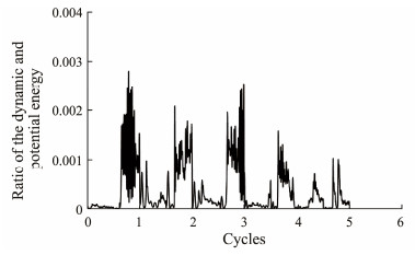
To simulate the coupling deformation of pipeline buckling and walking, on the one hand, the dynamic explicit method has a significant advantage in the convergence of pipeline buckling analysis (Liu and Li, 2018), especially for the global buckling caused by several heating and cooling cycles, wherein the improved static method risk is no longer applicable. Therefore, the dynamic method becomes an option. On the other hand, Fig. 2 shows that the magnitude of errors is acceptable despite errors between analytical and FEA results using the 3D explicit method. Moreover, the simulation results show that the ratio of dynamic and potential energy during the pipeline heating and cooling process is low, as shown in Fig. 3. This finding reflects the good convergence of dynamic analysis. Therefore, the dynamic explicit method is adopted to simulate the coupling deformation of pipeline walking and buckling in this study.
|
Fig. 3 Ratio of the dynamic and potential energy. |
A double-imperfection pipeline on the inclined seabed is considered to study the walking phenomenon of a buckling pipeline. As shown in Fig. 1, the spacing between two adjacent imperfections caused by buckling initiation techniques in pipeline engineering is usually 2 to 3 km (Sinclair et al., 2009; Wang et al., 2018). In this study, the pipeline length is set as 6000 m, and its two ends are free. The two imperfections (I and H) divide the 6000 m pipeline into three pipeline segments with lengths of 2000 m, where A, B, and C are the midpoints of each pipeline segment, as shown in Fig. 4. The wavelength L0 m of the two imperfections is 40 m, and the imperfection amplitudes V0 mI and V0 mH are 0.5 m. Other parameters of the pipeline are shown in Table 1.

|
Fig. 4 Pipeline with double imperfections. |
The seabed slope θ in Fig. 4 is modified to demonstrate the walking phenomenon of a buckling pipeline. The axial displacements of points A, B, and C during five heating and cooling cycles are shown in Fig. 5. The positive displacement in the figures refers to the axial movement toward the lower end of the seabed slope.

|
Fig. 5 Axial displacements of points A, B, and C in five heating and cooling cycles. |
Fig. 5(a) shows the absence of a cumulative axial movement at midpoint B of pipeline segment IH with increasing cycle numbers when the seabed slope is 0˚. When the seabed is 5˚ and 9˚, all axial displacements at points A, B, and C accumulate with cycle numbers, and the trend of axial displacement accumulation increases with the seabed slope. Thus, the walking phenomenon of a buckling pipeline on the inclined seabed is directly demonstrated.
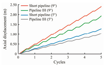
For pipelines with multiple imperfections, the walking of one pipeline segment between two adjacent imperfecttions is identical to that of pipeline segment IH in Fig. 4. Thus, the walking behavior of a pipeline with multiple imperfections can be studied on the basis of pipeline segment IH. The axial displacement at the midpoint of pipeline segment IH (2000 m) and that at the midpoint of a short straight pipeline with a length of 2000 m are shown in Fig. 6.
|
Fig. 6 Axial displacements of buckling pipeline segment IH and a short straight pipeline. |
Fig. 6 shows that for pipelines on a seabed of the same slope, the walking of the short straight pipeline is always larger than that of pipeline IH and the gap increases with the number of cycles. To study the cause of this gap, the axial force curves of pipeline segment IH and the short straight pipeline during five cycles are shown in Figs. 7 and 8, respectively, where letters M and N correspondingly represent the anchors during heating and cooling.

|
Fig. 7 Axial force of buckling pipeline segment IH during five cycles. |

|
Fig. 8 Axial force of the short straight pipeline during five cycles. |
The pipeline gravity component along the seabed slope combined with soil resistance on the pipeline causes the asymmetry in axial force along the pipeline. Therefore, virtual anchor M during the heating process does not coincide with virtual anchor N in the cooling process. The pipeline movement direction on both sides of one virtual anchor is indicated by the arrows in Fig. 7. The movement direction of pipeline segment MN points to the lower end of the seabed in heating and cooling processes. Therefore, the pipeline walks downward in the heating and cooling cycles.
The comparison between Figs. 7 and 8 shows the difference in axial force distribution at the ends of the short straight pipeline and pipeline segment IH. Unlike the complete free condition of the short straight pipeline, the end conditions of pipeline segment IH are determined by the buckling of the pipeline. This phenomenon is one of the reasons for the difference in walking between the buckling pipeline and the short straight pipeline. Another alternative reason lies in the difference in axial force along the short straight pipeline and pipeline segment IH, especially during the cooling process. Axial force curves of cooling 1 - 5 of the short straight pipeline almost overlap, whereas the residual axial force of pipeline IH increases with the rising cycles, which will eventually increase the distance between virtual anchor points M and N of the pipeline.
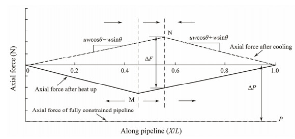
3.2 Analytical Solution for Walking of the Buckling Pipeline 3.2.1 Walking analytical solution of the short straight pipelineThe axial force curves of a short straight pipeline during a heating and cooling cycle, which is placed on the seabed inclined along the length direction of the pipeline, are shown in Fig. 9.
|
Fig. 9 Axial force curves of a short straight pipeline (2000 m) during a heating and cooling cycle. |
Carr et al. (2008) showed that the pipeline walking per cycle induced by the seabed inclination is equal to the expansion between two virtual anchors during one heating and cooling cycle.
Fig. 9 shows that the axial force of pipeline section MN changes as ΔF during the heating and cooling processes:
| $ \Delta F = L(\mu w\cos \theta - w\sin \theta) . $ | (3) |
The expansion amount per heating and cooling cycle of pipeline segment MN Xθ is:
| $ {X_\theta } = \frac{{\left| P \right| - L(\mu w\cos \theta - w\sin \theta)}}{{EA}}{X_{{\text{MN}}}} . $ | (4) |
According to the geometric relationship in Fig. 9, the spacing between virtual anchors M and N (XMN) is:
| $ {X_{{\text{MN}}}} = \frac{{L\tan \theta }}{\mu } . $ | (5) |
Thus, the walking per heating and cooling cycle at the midpoint of pipeline Xθ is:
| $ {X_\theta } = \left({\frac{{\left| P \right| - L(\mu w\cos \theta - w\sin \theta)}}{{EA\mu }}} \right)L\tan \theta . $ | (6) |
The meanings of the letters in Eqs. (3) - (6) are identical to the above.
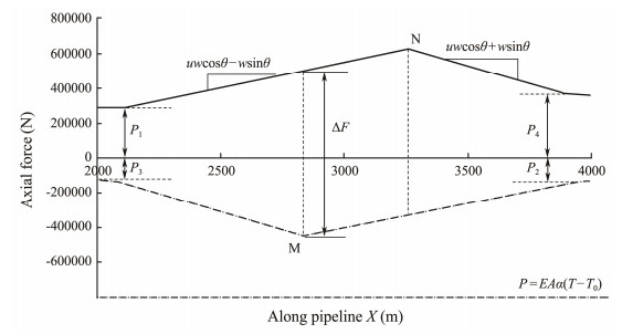
3.2.2 Analytical solution of walking for the buckling pipelineThe FEA results of pipeline walking have been relatively stable since the second cycle. Thus, the analytical solution of buckling pipeline axial movement is derived on the basis of the axial force curve of the second cycle in Fig. 7(a).
Fig. 10 shows that the change in axial force ΔF of pipeline section MN during the heating and cooling cycle is:
| $ \Delta F = L(\mu w\cos \theta - w\sin \theta) + \left| {{P_1}} \right| + \left| {{P_2}} \right| . $ | (7) |
|
Fig. 10 Axial force curves of pipeline IH (2000 m) during a heating and cooling cycle. |
P1 and P2 can be determined by the pipeline buckling analysis. Expansion amount Xθ per heating and cooling cycle of pipeline segment MN is:
| $ {X_\theta } = \frac{{\left| P \right| - \left[ {L(\mu w\cos \theta - w\sin \theta) + \left| {{P_1}} \right| + \left| {{P_2}} \right|} \right]}}{{EA}}{X_{{\text{MN}}}} . $ | (8) |
The geometric relationship in Fig. 10 shows that:
| $ \left\{ \begin{gathered} \mu w\cos \theta - w\sin \theta {\text{ = }}\frac{{({P_{\text{N}}} - {P_1}) + ({P_{\text{M}}} - {P_2})}}{{L + {X_{{\text{MN}}}}}} \hfill \\ \mu w\cos \theta + w\sin \theta {\text{ = }}\frac{{({P_{\text{N}}} - {P_4}) + ({P_{\text{M}}} - {P_3})}}{{L - {X_{{\text{MN}}}}}} \hfill \\ \end{gathered} \right. . $ | (9) |
P1 and P2 are approximately equal to P4 and P3, respectively, as shown in Fig. 10. Thus, Eq. (9) is simplified to:
| $ {X_{{\text{MN}}}} = \frac{{L\tan \theta }}{\mu }, $ | (10) |
| $ {X_\theta } = \left({\frac{{\left| P \right| - \left[ {L(\mu w\cos \theta - w\sin \theta) + \left| {{P_1}} \right| + \left| {{P_2}} \right|} \right]}}{{EA\mu }}} \right) \cdot L\tan \theta . $ | (11) |
Therefore, by comparing Figs. 10 and 7(a), the effect of the number of cycles on the analytical formula of walking is analyzed as follows. From cycles 1 to 5, axial forces P2 and P3 hardly change while P1 and P4 both accumulate with the cycle numbers. This phenomenon gradually increases the difference between P1 and P4 in Eq. (9); therefore, XMN increases accordingly. In addition, the growth in P1 will increase ΔF in Eq. (7).
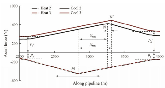
Take cycles 2 and 3 as examples to analyze the effect of changes in P1 and P4 on the walking analytical formula.
The geometric relationships in Fig. 11 show that
| $ {X_{{\text{MN'}}}} = {X_{{\text{MN}}}} + {X_{{\text{NN'}}}} = \frac{{L\tan \theta }}{\mu } + \frac{{{{P'}_4} - {{P'}_1}}}{{2\mu w\cos \theta }} . $ | (12) |
|
Fig. 11 Axial force of pipeline section IH in cycles 2 and 3 (seabed slope = 5˚). |
Thus,
| $ \begin{array}{l} {X_\theta } = \left({\frac{{\left| P \right| - \left[ {L(\mu w\cos \theta - w\sin \theta) + \left| {{{P'}_1}} \right| + \left| {{P_2}} \right|} \right]}}{{EA\mu }}} \right) \cdot\\ \;\;\;\;\;\;\;\;\; \left({L\tan \theta + \frac{{{{P'}_4} - {{P'}_1}}}{{2\mu w\cos \theta }}} \right) . \end{array} $ | (13) |
The comparison of Eqs. (13) and (11) shows that the increase in P1 weakens axial movement Xθ and the increment in the difference between P4 and P1 strengthens Xθ. Thus, the two factors have opposite effects. According to the buckling mechanism, the changes in P1 and P4 in each cycle are relatively small to P. In addition, if the effect of the changes in P1 and P4 on the walking is considered, then the walking of the buckling pipeline must be calculated cycle by cycle, which significantly increases the calculation cost. This study recommends simply adopting Eq. (11) to estimate the walking of buckling pipelines based on the aforementioned reasons.
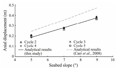
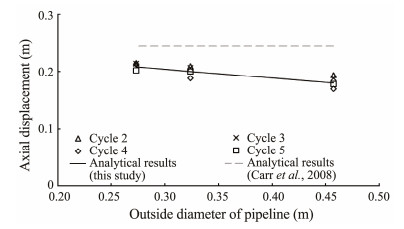
3.2.3 Validation of the analytic solution for the walking of a buckling pipelineThe analytical results of the walking of pipeline segment IH in a double-imperfection pipeline on the seabed of 5˚, 7˚, and 9˚ were determined by Eq. (11) and are plotted in Fig. 12 with the FEA results of axial displacement at the midpoint of pipeline segment IH during cycles 2 - 5. The analytical results determined by Carr et al. (2008) are also provided for comparison in Fig. 12.
|
Fig. 12 Analytical results vs. FEA results of each cycle. |
Fig. 12 shows that the analytical results determined by Eq. (11) and the FEA results have consistent trends with each other, but the analytical results determined by Carr et al. (2008) markedly differ from the numerical results. This difference is due to the analytical solution of Carr, which is derived from short straight pipelines and cannot be directly applied to the walking calculation of buckling pipelines. Thus, considering the influence of pipeline buckling force is necessary when calculating the walking of a buckling pipeline, as shown in Eq. (11).
Fig. 12 also reveals that the analytical results determined by Eq. (11) and the FEA results have consistent trends with each other, but some differences in specific values with an error of approximately 1% to 7% are found. The FEA results show that the walking error between cycles is within 10%. Two conclusions can be drawn from this analysis. First, the walking difference between cycles is limited, and the computational cost of going through each cycle is high. Therefore, the difference between cycles should be ignored to simplify the calculation. Second, when the cyclic effect on walking is ignored, the analytical results using Eq. (11) are consistent with the FEA results, which validates the proposed walking analytical solution of the buckling pipeline.
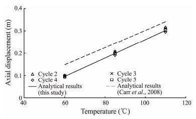
The comparison of the analytical and FEA results for pipelines with different outside diameters and operation temperatures is shown in Figs. 13 and 14 to further verify the applicability of the analytical solution for the walking of a buckling pipeline (Eq. (11)) for varying parameters, such as pipe size and environmental conditions.
|
Fig. 13 Analytical results vs. FEA results for pipelines with different outside diameters. |
|
Fig. 14 Analytical results vs. FEA results for pipelines with different temperatures. |
Figs. 13 and 14 show that for buckling pipelines with different outside diameters and operating temperatures, the FEA results of walking are consistent with the analytical results proposed in this paper. This finding verifies the applicability of the analytical solution for the walking of a buckling pipeline.
4 Influence Analysis of Walking on Global Buckling 4.1 Effect of Walking on the Capacity of the Buckling InitiationThe capacity of buckling initiation is one of the most important factors in pipeline buckling design. Thus, the influence analysis of walking on the critical axial force required for buckling is conducted through a group of double-imperfection pipelines (Fig. 4) on the seabed with a slope of 0˚, 5˚, and 9˚.
Fig. 15 shows that when the seabed slope is 0˚, the axial force at imperfections I and H completely coincide in five cycles, which indicates that the buckling axial forces during heating are consistent at imperfections I and H, and the same is true for the residual axial force during cooling. A slight difference in buckling axial force at imperfections I and H is observed for pipelines on the seabed with slopes of 5˚ and 9˚ when the cycle numbers increase. The effect of walking on the buckling axial force can be neglected because the difference is remarkably small. However, the residual axial force of pipelines on the seabed with slopes of 5˚ and 9˚ evidently varies with the number of cycles. The residual axial force at imperfection H is larger than that at imperfection I, and the difference accumulates with the cycle numbers.

|
Fig. 15 Axial force at imperfections I and H. |
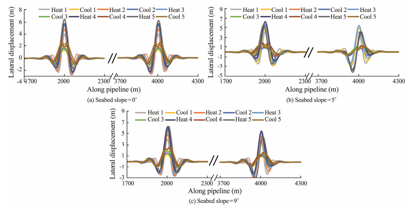
The lateral displacement curves along the pipeline on the seabed with slopes of 0˚, 5˚, and 9˚ are plotted as shown in Fig. 16 to analyze the effect of walking on the buckling mode.
|
Fig. 16 Lateral displacement curves of pipelines on the seabed with different slopes. |
Fig. 16 shows that the buckling of the pipeline at two imperfections is completely symmetrical for the case where the seabed slope is 0˚. However, buckling amplitude and mode at the two imperfections are no longer symmetrical when the seabed slope increases to 5˚ and 9˚. Take the case where the seabed slope is equal to 5˚ as an example to analyze the asymmetry phenomenon. The lateral displacement curves of each cycle are separately extracted to analyze the change process of the buckling mode during the cycles, as shown in Fig. 17.

|
Fig. 17 Lateral displacement curves of pipelines on a seabed with slope = 5˚. |
For pipeline imperfection H at the low end of the seabed slope, Fig. 17 shows that the maximum buckling amplitude decreases while the secondary buckling amplitude increases with the cycle numbers, facilitating the changes in buckling mode from 3 to 2 as described by Hobbs (1984). However, the modes remain unchanged for pipeline imperfection I at the high end of the seabed slope despite the limited variation of the pipe buckling amplitude with the number of cycles. This condition explains the gradual asymmetry of buckles at the two imperfections. In addition, this analysis shows that the effect of walking produces asymmetrical buckling at one imperfection; that is, the amplitudes of the secondary buckling on the left and right sides of the primary buckling are not equal, which is consistent with the study of Bruton et al. (2003).
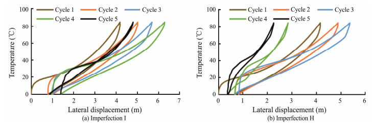
The lateral displacement at the midpoint of imperfections I and H during heating and cooling cycles is shown in Fig. 18.
|
Fig. 18 Lateral displacement at the midpoint of imperfections I and H (seabed slope = 5˚). |
Fig. 18 shows that the buckling displacement at the midpoint of the upslope imperfection I gradually increases from cycles 1 to 4 but decreases in the fifth cycle. Meanwhile, the downslope imperfection H shows an early and severely weakened trend of the buckling amplitude. Thus, for pipelines with multiple imperfections, further studying this walking effect, which weakens the maximum buckling amplitude of the pipeline, and its accumulation with imperfection numbers, is reasonable.
4.3 Effect of Walking on the Failure Assessment of a Buckling PipelineThe visual expression of the walking effect on pipeline buckling lies in the changes in buckling amplitude and mode. These changes are accompanied by variations in bending moment, stress, and strain. These factors may jeopardize the structural integrity and cause pipeline failure. Therefore, the influence analysis of walking on the failure assessment of global lateral buckling in pipelines is necessary.
DNV-OS-F101 (2012) suggests two design criteria for the failure assessment: displacement- and load-controlled criteria. A pipeline checked for displacement-controlled criteria will typically have tensile strains above 0.4%. Fracture assessment is required if tensile strains exceed 0.4%. For the load-controlled criterion, pipe members subjected to axial force and bending moment will be designed to satisfy the following criterion at all cross-sections.
| $ \eta = {\left\{ {{\gamma _{\text{m}}} \cdot {\gamma _{{\text{SC}}}} \cdot \frac{{\left| {{M_{{\text{Sd}}}}} \right|}}{{{\alpha _{\text{c}}} \cdot {M_{\text{p}}}}} + {{\left\{ {\frac{{{\gamma _{\text{m}}} \cdot {\gamma _{{\text{SC}}}} \cdot {S_{{\text{Sd}}}}}}{{{\alpha _{\text{c}}} \cdot {S_{\text{p}}}}}} \right\}}^2}} \right\}^2} \leqslant 1, $ | (14) |
where γm is the material resistance factor, γSC is the safety class resistance factor, MSd is the design moment, αc is the flow stress parameter, Mp is the plastic capacity of the moment, SSd is the design effective axial force, Sp is the plastic capacity of axial force, and η is the failure parameter; when η ≤ 1, the pipeline efficiently works under the current load combination. A large value of η, which corresponds to a high load, indicates a high failure probability.
The buckling results of the pipeline during five load cycles when the seabed slope is 0˚ are shown in Table 2. All integration points of each pipe element are checked, but only the worst point is presented in Table 2.
|
|
Table 2 Buckling results of the pipeline on a seabed with a slope of 0˚ |
Table 2 shows that failure parameters and total strain of the pipelines reach the peak in the first cycle. This finding is attributed to the weakened subsequent buckling deformation due to residual stress and strain in the pipeline generated at the end of the first cycle. Without walking (seabed slope = 0˚), the values of failure parameters at the two imperfections of the pipeline are close but only vary in the fifth cycle.
The pipeline laid on the seabed with a slope of 9˚ is taken as a case to analyze the effect of walking on the failure assessment of the buckling pipeline. The failure assessment of global buckling in pipelines with walking during five heating and cooling cycles is described in Table 3.
|
|
Table 3 Buckling results of the pipeline on a seabed with a slope of 9˚ |
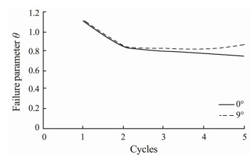
Similar to the pipelines in Table 2, failure parameters and total strain of the pipelines are maximal in the first cycle in Table 3. However, the failure parameters at the two imperfections differ after the first cycle, as well as the total strain for the pipeline with walking (seabed slope = 9˚). This finding indicates that pipeline walking affects the failure assessment of global lateral buckling in pipelines.
Fig. 19 shows the comparison of the failure parameters of the pipelines with seabed slopes of 0˚ and 9˚ in Tables 1 and 3, respectively.
|
Fig. 19 Failure parameters of the pipelines with/without walking. |
Fig. 19 shows that the failure parameters of the pipelines with/without walking are approximately identical to each other in the first and second cycles. With the increase in the cycles, the failure parameter of the pipeline with walking (seabed slope = 9˚) is gradually larger than that of the pipeline without walking (seabed slope = 0˚). This finding indicates that pipeline walking is unfavorable to the integrity of a pipeline that exhibits global buckling.
5 ConclusionsGlobal lateral buckling is mainly used to release the axial force of submarine pipelines subjected to high temperatures and pressures. However, the buckling at multiple locations of a long pipeline may divide the originally fully constrained pipeline into multiple short pipeline segments, which may increase the risk of pipeline walking. Thus, a pipeline, which is designed to buckle laterally, may laterally and axially displace over time when subjected to repeated heating and cooling cycles. Hence, the coupling deformation of global lateral buckling and walking of submarine pipelines is studied with theoretical and FEA methods. The conclusions are as follows.
1) A walking phenomenon in the pipeline segment between two adjacent buckles is observed for a buckled pipeline laid on an inclined seabed. This buckling pipeline segment walks differently from a short straight pipeline for two reasons. The end conditions of the pipeline segment determined by the buckling are different from the complete free condition of the short straight pipeline. The residual axial force of the pipeline segment and distance between two anchors MN change with the increase in cycles, while those of the short straight pipeline remain unchanged.
2) Compared with the walking of the short straight pipeline, the axial movement mechanism of the long pipeline with global buckling is analyzed. An analytical solution for the walking of buckling pipelines is proposed on the basis of the aforementioned analysis. Subsequently, the sensitivity of this method to heating and cooling cycles is analyzed, which validates the proposed walking analytical solution of the buckling pipeline.
3) The effect of walking on the buckling axial force is negligible. The effect of pipeline walking on post-buckling can be described as the gradually asymmetric buckling at various imperfections with heating and cooling cycles. In addition, the buckling at one imperfection is no longer symmetrical.
4) The influence analysis of walking on the failure assessment of buckling pipelines shows that the pipelines with/without walking have identical failure parameters in the first and second cycles. With the increase in cycle numbers of heating and cooling, the failure parameters of the pipeline with walking (seabed slope = 9˚) are gradually larger than those of the pipeline without walking (seabed slope = 0˚), which indicates that the pipeline walking is unfavorable for pipeline safety.
AcknowledgementsThe study is supported by the China National Postdoctoral Program for Innovative Talents (No. BX2021213), and the Natural Science Foundation for Distinguished Young Scholars of China (No. 51825904).
Bruton, D. A. S., Carr, M., Sinclair, F., and MacRae, I., 2010. Lessons learned from observing walking of pipelines with lateral buckles including new driving mechanisms and updated analysis models. Offshore Technology Conference. Houston, Texas, OTC-20750-MS.
(  0) 0) |
Bruton, D., and Carr, M., 2005. The safe design of hot on-bottom pipelines with lateral buckling using the design guideline developed by the SAFEBUCK Joint Industry Project. Proceedings of the Deep Offshore Technology Conference. Vitoria, Espirito Santo, 1-26.
(  0) 0) |
Bruton, D., Carr, M., and Leslie, D., 2003. Lateral buckling and pipeline walking, a challenge for hot pipelines. Offshore Pipeline Technology Conference. Amsterdam, 1-35.
(  0) 0) |
Carneiro, D., Gouveia, J., Parrilha, R., Oazen, E., Tardelli, L., and Cardoso, C., 2009. Design of small diameter HT/HP sour service reeled rigid pipelines. Proceedings of the 7th Rio Pipeline Conference. Rio de Janeiro. 1-10.
(  0) 0) |
Carr, M., Sinclair, F., and Bruton, D., 2008. Pipeline walking-understanding the field layout challenges, and analytical solutions developed for the SAFEBUCK JIP. Offshore Pipeline Technology Conference. Houston, 3 (3): 1-9.
(  0) 0) |
Cumming, G., Druzynski, A., Tørnes, K., and Rathbone, A., 2009. Lateral walking and feed-in of buckled pipelines due to interactions of seabed features. Proceedings of the 28th International Conference on Offshore Mechanics and Arctic Engineering. Honolulu, 739-751.
(  0) 0) |
DNV-OS-F101, 2012. Submarine Pipeline Systems. Det Norske Veritas (DNV), Akershus, Norway, 75-76.
(  0) 0) |
Hobbs, R. E., 1984. In-service buckling of heated pipelines. Journal of Transportation Engineering, 110(2): 175-189. DOI:10.1061/(ASCE)0733-947X(1984)110:2(175) (  0) 0) |
Hong, Z., Liu, W., and Xu, B., 2021. Research on the pipeline walking caused by cyclic increasing soil friction for free deep-sea submarine pipelines laid on even seabed. Marine Structures, 75: 102873. DOI:10.1016/j.marstruc.2020.102873 (  0) 0) |
Li, C., and Liu, R., 2020. Numerical investigation into the effects of different initial imperfections on the lateral buckling of submarine pipelines. Ocean Engineering, 195: 106752. DOI:10.1016/j.oceaneng.2019.106752 (  0) 0) |
Li, G., Zhan, L., and Li, H., 2016. An analytical solution to lateral buckling control of subsea pipelines by distributed buoyancy sections. Thin-Walled Structures, 107: 221-230. DOI:10.1016/j.tws.2016.06.003 (  0) 0) |
Liu, R., and Li, C., 2018. Determinate dimension of numerical simulation model in submarine pipeline global buckling analysis. Ocean Engineering, 152: 26-35. DOI:10.1016/j.oceaneng.2018.01.014 (  0) 0) |
Liu, R., and Wang, X. Y., 2018. Lateral global buckling of submarine pipelines based on the model of nonlinear pipe-soil interaction. China Ocean Engineering, 32(3): 312-322. DOI:10.1007/s13344-018-0032-y (  0) 0) |
Liu, R., Li, C., and Peng, B., 2020. Axial pipe-soil interaction during pipeline-walking analysis of pipelines placed on Bohai sand. Applied Ocean Research, 99: 102133. DOI:10.1016/j.apor.2020.102133 (  0) 0) |
Liu, R., Liu, W., Yan, S., and Hong, Z., 2016. Finite-element study of methods for triggering pipeline global buckling based on the concept of the perfect VAS length. Journal of Pipeline Systems Engineering and Practice, 7(2): 04015027. DOI:10.1061/(ASCE)PS.1949-1204.0000228 (  0) 0) |
Liu, R., Xiong, H., Wu, X., and Yan, S., 2014. Numerical studies on global buckling of subsea pipelines. Ocean Engineering, 78: 62-72. DOI:10.1016/j.oceaneng.2013.12.018 (  0) 0) |
Luo, Y., Ferdous, Z., and Leslie, W. D., 2013. Post-buckling analysis of snaked-lay pipelines based on a new deformation shape. Journal of Offshore Mechanics & Arctic Engineering, 135(3): 031704. (  0) 0) |
Matheson, I., Carr, M., Peek, R., Saunders, P., and George, N., 2004. Penguins flowline lateral buckle formation analysis and verification. ASME 2004 23rd International Conference on Offshore Mechanics and Arctic Engineering. Vancouver, British Columbra, 67-76.
(  0) 0) |
Peek, R., Matheson, I., Carr, M., Saunders, P., and George, N., 2004. Thermal expansion by lateral buckling: Structural reliability analysis for the Penguins flowline. ASME 2004 23rd International Conference on Offshore Mechanics and Arctic Engineering. Vancouver, British Columbra, 49-55.
(  0) 0) |
Perinet, D., and Simon, J., 2011. Lateral buckling and pipeline walking mitigation in deep water. Offshore Technology Conference. Houston, Texas, OTC-21803-MS.
(  0) 0) |
Rong, H., Inglis, R., Bell, G., Huang, Z., and Chan, R., 2009. Evaluation and mitigation of axial walking with a focus on deep water flowlines. Offshore Technology Conference. Houston, Texas, OTC-19862-MS.
(  0) 0) |
Seyfipour, I., Bahaari, M. R., and Mirghaderi, R., 2021. Efficient methods to mitigate SCR-induced walking of short subsea flowlines. Marine Structures, 76: 102891. DOI:10.1016/j.marstruc.2020.102891 (  0) 0) |
Seyfipour, I., Walker, A., and Kimiaei, M., 2019. Local buckling of subsea pipelines as a walking mitigation technique. Ocean Engineering, 194: 106626. DOI:10.1016/j.oceaneng.2019.106626 (  0) 0) |
Sinclair, F., Carr, M., Bruton, D., and Farrant, T., 2009. Design challenges and experience with controlled lateral buckle initiation methods. ASME 2009 28th International Conference on Ocean, Offshore and Arctic Engineering. Honolulu, Hawaii, 319-330.
(  0) 0) |
Solano, R. F., Antunes, B. R., Hansen, A. S., Sriskandarajah, T., Charnaux, C. R., Ragupathy, P., et al., 2014. Lateral buckling and walking design of a pipeline subjected to a high number of operational cycles on very uneven seabed. International Conference on Offshore Mechanics and Arctic Engineering. American Society of Mechanical Engineers, San Francisco, 45462: V06AT04A020.
(  0) 0) |
Teigen, M., and Ibrahim, M., 2015. Investigation of the behaviour of the lateral buckling control method: Reel-lay induced imperfection. ASME 2015 34th International Conference on Ocean, Offshore and Arctic Engineering. St. John's, Newfoundland, OMAE2015-41848, V05AT04A019.
(  0) 0) |
Teigen, M., and Ibrahim, M., 2017. Validation of residual curvature installation for lateral buckling management using structural reliability analysis (SRA). Proceedings of the ASME 2017 36th International Conference on Ocean. Offshore and Arctic Engineering, Trondheim, 1-10.
(  0) 0) |
Thompson, H. M., Reiners, J., Brunner, M. S., DeLack, K., Qui, X., and Noel, C., 2009. Tahiti flowline expansion control system. Offshore Technology Conference. Houston, Texas, OTC-19858-MS.
(  0) 0) |
Tørnes, K., Ose, B. A., Jury, J., and Thomson, P., 2000. Axial creeping of high temperature flowlines caused by soil ratcheting. ETCE/OMAE2000 Joint Conference: Energy for the New Millenium. New Orleans, 1229-1240.
(  0) 0) |
Wang, J., and Jukes, P., 2008. An integrated design approach to the use of sleepers as vertical upsets for thermal buckle management. 2008 7th International Pipeline Conference. Calgary, 181-188.
(  0) 0) |
Wang, Z., and Tang, Y., 2020. Analytical study on controlled lateral thermal buckling of antisymmetric mode for subsea pipelines triggered by sleepers. Marine Structures, 71: 102728. DOI:10.1016/j.marstruc.2020.102728 (  0) 0) |
Wang, Z., Tang, Y., and Heijden, G. H. M. V. D., 2018. Analytical study of distributed buoyancy sections to control lateral thermal buckling of subsea pipelines. Marine Structures, 58: 199-222. DOI:10.1016/j.marstruc.2017.11.008 (  0) 0) |
Zhou, J., Liu, Y., and Li, X., 2010. Pipe walking-lateral buckling interaction. In: Earth and Space 2010: Engineering, Science, Construction, and Operations in Challenging Environments. ASCE, 3318-3327.
(  0) 0) |
 2023, Vol. 22


