随着深井超深井、高温高压气井、含腐蚀介质气井、热采井等复杂恶劣工况下油气开发日益增多,油套管气密封特殊螺纹接头已得到广泛应用[1-3]。特殊螺纹接头通常具有能满足接头连接强度的改进偏梯形螺纹结构、特殊的金属对金属接触密封结构,同时还具有扭矩止推台肩。然而,要保证接头密封完整性和结构完整性,上扣时不仅要控制最大扭矩在合理范围,而且还应有合理的扭矩分布。由于特殊螺纹接头种类繁多、结构复杂,目前国际上还没有特殊螺纹接头产品质量规范,仅有国际标准ISO13679[4] 中提供了特殊螺纹油套管的性能评价和选择方法。对其上扣扭矩的研究也主要采用实物试验法[5-7] 和有限元方法[8-10],而相关的理论计算方法很少。
为此,本文分析了特殊螺纹接头典型上扣扭矩曲线各部分扭矩构成,基于弹性力学厚壁圆筒理论和旋转台肩扭矩法尔公式,建立了特殊螺纹接头上扣扭矩理论计算公式,研究了不同因素对接头上扣扭矩及其构成的影响规律,以期为特殊螺纹接头优化设计、上扣扭矩控制和强度计算提供理论依据。
1 特殊螺纹接头典型上扣扭矩分析油套管特殊螺纹接头通常采用改进的偏梯形螺纹结构来满足接头拉伸强度高于管体本体强度要求,同时采用专门设计的金属对金属径向密封结构满足接头密封要求。此外,绝大多数特殊螺纹接头在密封区域端部还设计有控制上扣扭矩和辅助密封的扭矩台肩结构(图 1)。
 |
| 图1 常用的油套管特殊螺纹接头示意图 Fig. 1 The schematic diagram of common used premium threaded connections |
由于存在密封面和台肩面,特殊螺纹接头与API 常规螺纹接头上扣扭矩曲线有很大差异,图 2为典型特殊螺纹接头从引扣到上扣完成扭矩-圈数关系曲线。
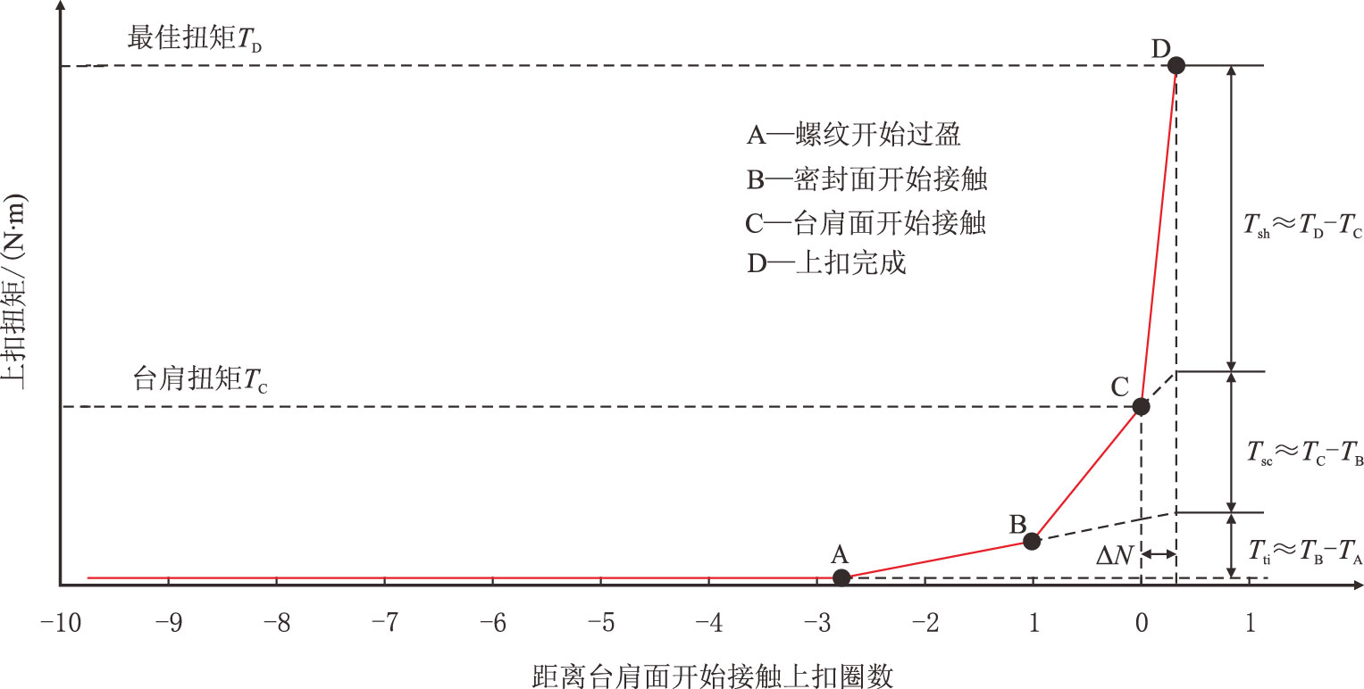 |
| 图2 典型特殊螺纹接头上扣扭矩-圈数关系曲线 Fig. 2 The typical relation curve between makeup torque and turns for premium threaded connections |
分析可知,特殊螺纹接头上扣扭矩主要包括引扣扭矩、螺纹过盈扭矩、作用到密封面上扭矩和作用到台肩面扭矩4 部分,其最佳上扣扭矩为
| $ {T_{\rm D}} = {T_{\rm A}} + {T_{{\rm{ti}}}} + {T_{{\rm{se}}}} + {T_{{\rm{sh}}}}$ | (1) |
式中:
$T_{\rm D}$—最佳上扣扭矩,N⋅m;
$T_{\rm A}$—引扣扭矩或称参考扭矩,N⋅m;
$T_{\rm{ti}}$—螺纹过盈扭矩,N⋅m;
$T_{\rm{se}}$—作用到密封面扭矩,N⋅m;
$T_{\rm{sh}}$—作用到台肩面扭矩,N⋅m。
除引扣扭矩外,实验中各部分扭矩值一般均无法直接检测。考虑密封面长度一般很小,则各部分扭矩可以作近似处理,最佳上扣扭矩也可表达为
| $ {T_{\rm D}} = {T_{\rm A}} + \left( {{T_{\rm B}} - {T_{\rm A}}} \right) + \left( {{T_{\rm C}} - {T_{\rm B}}} \right) + \\\hspace{4em}\left( {{T_{\rm D}} - {T_{\rm C}}} \right)$ | (2) |
式中:
$T_{\rm B}$—密封面开始接触时扭矩,N⋅m;
$T_{\rm C}$—台肩开始接触扭矩,简称台肩扭矩,N⋅m。
2 上扣扭矩理论计算方法 2.1 螺纹面和密封面接触应力上扣完成后,螺纹牙间和密封面间形成的径向过盈量将在接触面之间产生接触应力,这种情况类似于空心圆筒的过盈配合,若沿接触面将管体和接箍简化为多个微小圆柱体接触组合,那么接触应力就可以通过弹性力学厚壁圆筒理论计算。管体内筒和接箍外筒径向过盈配合如图 3 所示。
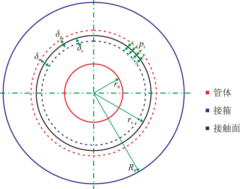 |
| 图3 管体内筒和接箍外筒径向过盈配合示意图 Fig. 3 The schematic diagram of radial interference fit between inner pin and outer coupling |
根据拉梅应力公式[11],内半径为a,外半径为b的厚壁圆筒在内压$p_{\rm i}$、外压$p_{\rm o}$ 作用下圆筒中任意点的径向位移为
| $ {u_{\rm r}} = \dfrac{{1 - \nu }}{E} \cdot \dfrac{{{a^2}{p_{\rm i}} - {b^2}{p_{\rm o}}}}{{{b^2} - {a^2}}} \cdot r + \\\hspace{3em}\dfrac{{1 + \nu }}{E} \cdot \dfrac{{{a^2}{b^2}\left( {{p_{\rm i}} - {p_{\rm o}}} \right)}}{{{b^2} - {a^2}}} \cdot \dfrac{1}{r}$ | (3) |
式中:
$u_{\rm r}$—圆筒中任意点的径向位移,mm;
$\nu$—泊松比,无因次;
E—弹性模量,MPa;
a—圆筒内半径,mm;
b—圆筒外半径,mm;
$p_{\rm{i}}$—内压,MPa;
$p_{\rm{o}}$—外压,MPa;
r—圆筒中任意点半径,mm。
对管体内筒,接触应力$p_{\rm r}$可认为是外压$p_{\rm o}$,而其内压等于零。
在式(3)中,令$a=r_0$,$b=r=r_{\rm c}$,$p_{\rm i}=0$,$p_{\rm o}=p_{\rm r}$,可得管体内筒外表面径向收缩量为
| ${\delta _{\rm p}} = - \dfrac{{{r_{\rm c}}{p_{\rm r}}}}{{{E_{\rm p}}}}\left( {\dfrac{{r_{\rm c}^2 + r_0^2}}{{r_{\rm c}^2 - r_0^2}} - {\nu _{\rm p}}} \right)$ | (4) |
式中:
$\delta_{\rm p}$—管体内筒外表面径向收缩量,mm;
$r_{\rm c}$—接触面半径,mm;
$p_{\rm r}$—径向接触应力,MPa;
$E_{\rm p}$—管体弹性模量,MPa;
$r_0$—管体内半径,mm;
$\nu_{\rm p}$—管体泊松比,无因次。
对接箍外筒,接触应力$p_{\rm r}$可认为是内压$p_{\rm i}$,而其外压等于零。
在式(3)中令$a=r=r_{\rm c}$,$b=R_0$,$p_{\rm i}=p_{\rm r}$,$p_{\rm o}=0$,可得接箍外筒内表面径向伸长量为
| $ {\delta _{\rm c}} = \dfrac{{{r_{\rm c}}{p_{\rm r}}}}{{{E_{\rm c}}}}\left( {\dfrac{{R_0^2 + r_{\rm c}^2}}{{R_0^2 - r_{\rm c}^2}} + {\nu _{\rm c}}} \right)$ | (5) |
式中:
$\delta_{\rm c}$—接箍外筒内表面径向伸长量,mm;
$E_{\rm c}$—接箍弹性模量,MPa;
$R_0$—接箍外半径,mm;
$\nu_{\rm c}$—接箍泊松比,无因次。
由图 3 可知,$\delta_{\rm p}$、$\delta_{\rm c}$绝对值之和应等于径向过盈量$\delta_{\rm r}$,即
| $\left| {{\delta _{\rm p}}} \right| + \left| {{\delta _{\rm c}}} \right| = {\delta _{\rm r}}$ | (6) |
式中:
$\delta_{\rm r}$—径向过盈量,mm。
将式(4)、式(5)代入式(6),得径向接触应力为
| ${p_{\rm r}} = \dfrac{{{\delta _{\rm r}}}}{{{r_{\rm c}}\left[ {\dfrac{1}{{{E_{\rm p}}}}\left( {\dfrac{{r_{\rm c}^2 + r_0^2}}{{r_{\rm c}^2 - r_0^2}} - {\nu _{\rm p}}} \right) + \dfrac{1}{{{E_{\rm c}}}}\left( {\dfrac{{R_0^2 + r_{\rm c}^2}}{{R_0^2 - r_{\rm c}^2}} + {\nu _{\rm c}}} \right)} \right]}}$ | (7) |
考虑大多数情况下油套管螺纹联接中管体和接箍材料相同,式(7)可简化为
| ${p_{\rm r}} = \dfrac{{E{\delta _{\rm r}}\left( {R_0^2 - r_{\rm c}^2} \right)\left( {r_{\rm c}^2 - r_0^2} \right)}}{{2r_{\rm c}^3\left( {R_0^2 - r_0^2} \right)}}$ | (8) |
其中,径向过盈量可由图 2 中附加上扣圈数确定
| $\left\{ \begin{array}{l} \delta _{\rm{tr}}=\left( {N_{\rm D} - N_{\rm A}} \right)P\tan {\gamma _{\rm t}}\hspace{2em} \text{螺纹面}\\ {\delta _{{\rm{sr}}}}{\rm{ = }}\left( {{N_{\rm D}} - {N_{\rm B}}} \right)P\tan {\gamma _{\rm{s}}}\hspace{2.3em} \text{密封面}\\ \end{array} \right.$ | (9) |
式中:
$\delta_{\rm{tr}}$—螺纹面径向过盈量,mm;
$\delta_{\rm{sr}}$—密封面径向过盈量,mm;
$N_{\rm{D}}$,$N_{\rm{A}}$,$N_{\rm{B}}$—图 2 中D、A、B 点对应的上扣圈数,圈;
P—螺距,mm;
$\gamma_{\rm t}$—螺纹半锥角,(°);
$\gamma_{\rm s}$—密封面半锥角,(°)。
2.2 螺纹过盈接触摩擦扭矩特殊螺纹接头一般采用改进的偏梯形螺纹牙,为防止井下螺纹倒扣必须保证足够螺纹径向过盈量。特殊螺纹接头螺纹过盈方式主要有齿顶-齿根过盈(C-R)和齿侧过盈(F-F)两种,对比见表 1。
| 表1 特殊螺纹接头螺纹牙过盈方式对比 Table 1 The comparison of thread tooth interference type of premium threaded connections |
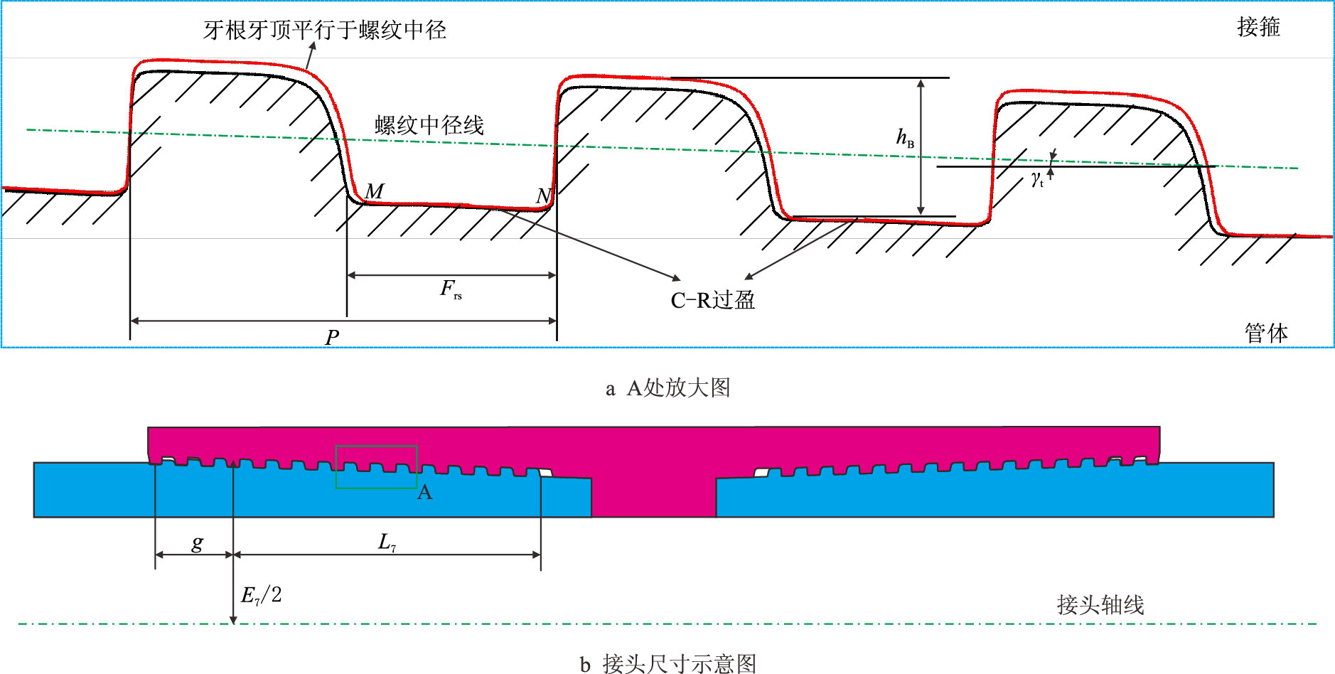 |
| 图4 特殊螺纹接头C-R 过盈接触示意图 Fig. 4 The schematic diagram of interference fit between crest and root for premium threaded connections |
管体螺纹牙根与接箍螺纹牙顶实际接触线为MN,因而接触面半径为
| ${r_{\rm c}}=\left(E_7 - {h_{\rm B}}\right)/2 - x\tan {\gamma _{\rm{t}}}\hspace{1em} (-g \leqslant x \leqslant{L_7})$ | (10) |
式中:$L_7$—完整螺纹长度,mm;
$E_7$—螺纹中径,mm;
$h_{\rm B}$—完整螺纹牙工作高度,mm;
x—坐标值,mm。
从而,螺纹过盈摩擦力矩可通过沿所有接触线$\Sigma {MN}$积分得到
| $ T_{\rm{ti}}= \dfrac{1}{1000} \cdot \int_{\Sigma {MN}} \dfrac{p_{\rm{r}}}{\cos {\gamma _{\rm t}}} \cdot 2\pi \cdot {r_{\rm c}} \cdot \dfrac{{\rm d}x}{\cos {\gamma_{\rm t}}} \cdot {\mu _{\rm t}} \cdot {r_{\rm c}}= \\\hspace{3em} \dfrac{1}{1000} \cdot \dfrac{F_{\rm{rs}}}{P} \cdot \int_{-g}^{L_7} {\dfrac{2\pi {\mu _{\rm t}}{p_{\rm{r}}}{r_{\rm c}^2}}{\cos{\gamma_{\rm t}}^2}} {\rm d}x = \\\hspace{4em} \dfrac{1}{{1000}} \cdot \dfrac{F_{\rm{rs}}}{P} \cdot \dfrac{\pi {\mu_{\rm t}}E{\delta_{\rm{tr}}}}{{\left( {R_0^2 - r_0^2} \right){{\cos }^2}{\gamma _{\rm t}}}}\int_{ - g}^{{L_7}} {\dfrac{{\left( {R_0^2 - r_{\rm c}^2} \right)\left( {r_{\rm c}^2 - r_0^2} \right)}}{{{r_{\rm c}}}}} {\rm{d}}x = \\\hspace{5em} \dfrac{{\pi E{\delta _{\rm{tr}}}{F_{\rm{rs}}}{\mu _{\rm t}}}}{{{\rm{4000}}\left( {r_0^2 - R_0^2} \right)P\sin {\gamma _{\rm t}}{{\cos }^2}{\gamma _{\rm t}}}}\\ \left\{ \begin{array}{l} {\left( {\dfrac{{{E_{\rm{7}}}}}{{\rm{2}}}{\rm{ - }}\dfrac{{{h_{\rm{B}}}}}{{\rm{2}}}{\rm{ + }}g\tan {\gamma _{\rm{t}}}} \right)^{\rm{4}}}{\rm{ - }}{\left( {\dfrac{{{E_{\rm{7}}}}}{{\rm{2}}}{\rm{ - }}\dfrac{{{h_{\rm{B}}}}}{{\rm{2}}}{\rm{ - }}{L_{\rm{7}}}\tan {\gamma _{\rm{t}}}} \right)^{\rm{4}}}{\rm{ + }} \\ \\ 4R_{\rm{0}}^{\rm{2}}r_{\rm{0}}^{\rm{2}}\ln \dfrac{{{E_{\rm{7}}}{\rm{ - }}{h_{\rm{B}}}{\rm{ + 2}}g\tan {\gamma _{\rm{t}}}}}{{{E_{\rm{7}}}{\rm{ - }}{h_{\rm{B}}}{\rm{ - 2}}{L_{\rm{7}}}\tan {\gamma _{\rm{t}}}}}{\rm{ + }} \\ \\ {\rm{2}}\left( {R_{\rm{0}}^{\rm{2}}{\rm{ + }}r_{\rm{0}}^{\rm{2}}} \right)\left[ {\left( {L_{\rm{7}}^{\rm{2}}{\rm{ - }}{g^{\rm{2}}}} \right)\tan {\gamma _{\rm{t}}}{\rm{ - }}\left( {{E_{\rm{7}}}{\rm{ - }}{h_{\rm{B}}}} \right)\left( {g{\rm{ + }}{L_{\rm{7}}}} \right)} \right]\tan {\gamma _{\rm{t}}} \\ \end{array} \right\}$ | (11) |
式中:
$T_{\rm{ti}}$—螺纹过盈摩擦力矩,N⋅m;
$F_{\rm{rs}}$—偏梯形螺纹牙底宽度,mm;
g—非完整螺纹长度,mm;
$\mu_{\rm t}$—螺纹面摩擦系数,无因次。
2.3 作用到密封面上扭矩作用到密封面扭矩包括密封面接触应力产生的螺纹力矩和密封面摩擦力矩。
(1)密封面接触应力产生的螺纹力矩
由于密封面具有一定锥度,密封面接触应力会产生一个轴向预紧力。该轴向预紧力使得螺纹旋合段产生螺纹力矩。锥面对锥面密封结构如图 5 所示,密封面实际接触线为PQ,因而接触面半径为
| ${r_{\rm c}}={r_{\rm{s}0}} + x\tan {\gamma _{\rm{s}}}\hspace{2em} (0 \leqslant x \leqslant {L_{\rm{s}}})$ | (12) |
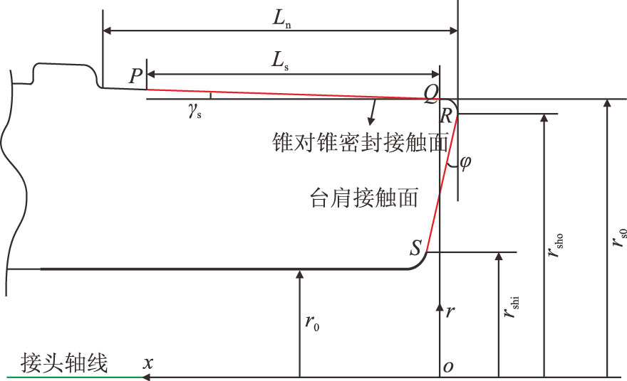 |
| 图5 锥面对锥面密封结构示意图 Fig. 5 The schematic diagram of cone to cone sealing structure |
密封面产生的轴向预紧力可通过沿PQ 积分得到
| $ {{F_{{\rm{se}}}} = \int_0^{{L_{\rm{s}}}} {\dfrac{{{p_{\rm{r}}}\tan {\gamma _{\rm{s}}}\cdot2\pi \cdot{r_{\rm{c}}}}}{{\cos {\gamma _{\rm{s}}}}}} {\rm{d}}x = \\\dfrac{{\pi E{\delta _{{\rm{sr}}}}\tan {\gamma _{\rm{s}}}}}{{\left( {R_0^2 - r_0^2} \right)\cos {\gamma _{\rm{s}}}}}\int_0^{{L_{\rm{s}}}} {\dfrac{{\left( {R_0^2 - r_{\rm{c}}^2} \right)\left( {r_{\rm{c}}^2 - r_0^2} \right)}}{{r_{\rm{c}}^2}}{\rm{d}}x} = } \\ \hspace{3em} {\dfrac{{\pi E{\delta _{{\rm{sr}}}}}}{{\left( {R_0^2 - r_0^2} \right)\cos {\gamma _{\rm{s}}}}}\\\left\{ {\dfrac{1}{3}\left[ {r_{{\rm{s}}0}^3 - {{\left( {{r_{{\rm{s}}0}} + {L_{\rm{s}}}\tan {\gamma _{\rm{s}}}} \right)}^3}} \right] + \\{L_{\rm{s}}}\left( {R_0^2 + r_0^2} \right)\tan {\gamma _{\rm{s}}} + R_0^2r_0^2\left( {\dfrac{1}{{{r_{s0}} + {L_{\rm{s}}}\tan {\gamma _{\rm{s}}}}} - \dfrac{1}{{{r_{{\rm{s}}0}}}}} \right)} \right\}}$ | (13) |
式中:$F_{\rm{se}}$—密封面产生的轴向预紧力,N;
$L_{\rm{s}}$—密封面轴向长度,mm;
$r_{\rm{s0}}$—密封面鼻端半径,mm。
从而,密封面产生的螺纹力矩可由法尔公式[12]计算
| ${T_{\rm{set}}} = \dfrac{{{F_{\rm{se}}}}}{{1000}}\left( {\dfrac{P}{{2\pi }} + \dfrac{{{\mu _{\rm t}}{R_{\rm t}}}}{{\cos \alpha }}} \right)$ | (14) |
其中
| ${R_{\rm t}} = \dfrac{{{E_7} + \left( {g - {L_7}} \right)\tan {\gamma _{\rm t}}}}{2}$ | (15) |
式中:
$T_{\rm{set}}$—密封面产生的螺纹力矩,N⋅m;
$R_{\rm{t}}$—螺纹摩擦力矩当量力臂,mm;
$\alpha$—支撑面角,(°)。
(2)密封面摩擦力矩
密封面摩擦力矩也可通过沿PQ 积分得到
| $ T_{\rm{sef}} = \dfrac{1}{1000} \cdot \int_0^{L_{\rm s}} {\dfrac{p_{\rm{r}}}{\cos {\gamma _{\rm s}}} \cdot 2\pi \cdot {r_{\rm c}} \cdot \dfrac{{\rm d}x}{\cos {\gamma _{\rm {\rm s}}}} \cdot {\mu _{\rm{se}}} \cdot {r_{\rm c}}}= \\ \hspace{3em} \dfrac{{\pi E{\delta _{\rm{sr}}}{\mu _{\rm{se}}}}}{1000{\left({R_0^2 - r_0^2} \right){{\cos }^2}{\gamma _{\rm s}}}}\int_0^{{L_{\rm s}}} {\dfrac{{\left( {R_0^2 - r_{\rm c}^2} \right)\left( {r_{\rm c}^2 - r_0^2} \right)}}{{{r_{\rm c}}}}} {\rm d}x = \\ \hspace{4em} \dfrac{{\pi E{\delta _{\rm{sr}}}{\mu _{\rm{se}}}}}{{2000\left( {R_0^2 - r_0^2} \right)\sin {\gamma _{\rm s}}{{\cos }^2}{\gamma _{\rm s}}}}\left\{ \begin{array}{l} \dfrac{1}{2}\left[ {r_{{\rm s}0}^4 - {{\left( {{r_{{\rm s}0}} + {L_{\rm s}}\tan {\gamma _{\rm s}}} \right)}^4}} \right] + \\2R_0^2r_0^2\ln \dfrac{{{r_{{\rm s}0}}}}{{{r_{v0}} + {L_{\rm s}}\tan {\gamma _{\rm s}}}}+ \\ \left( {R_0^2 + r_0^2} \right)\left[ {{{\left( {{L_{\rm s}}\tan {\gamma _{\rm s}}} \right)}^2} + \\2{r_{{\rm s}0}}{L_{\rm s}}\tan {\gamma _{\rm s}}} \right] \\ \end{array} \right\}$ | (16) |
式中:
$T_{\rm{sef}}$—密封面产生的摩擦力矩,N⋅m;
$\mu_{\rm{se}}$—密封面摩擦系数,无因次。
2.4 作用到台肩面上扭矩作用到台肩面扭矩包括台肩面接触应力产生的螺纹力矩和台肩面摩擦力矩。
(1)台肩面接触应力产生的螺纹力矩
台肩面实际接触线为图 5 中RS ,若台肩面上接触应力均匀分布,则台肩面产生的轴向预紧力为
| ${F_{\rm{sh}}} = {p_{\rm{sh}}}\cos \varphi \cdot \dfrac{{\pi \left( {r_{\rm{sho}}^2 - r_{\rm{shi}}^2} \right)}}{{\cos \varphi }} =\\\hspace{3em} \pi {p_{\rm{sh}}}\left( {r_{\rm{sho}}^2 - r_{\rm{shi}}^2} \right)$ | (17) |
式中:
$F_{\rm{sh}}$—台肩面产生的轴向预紧力,N;
$p_{\rm{sh}}$—台肩接触应力,MPa;
$\varphi$—台肩倒角,(°);
$r_{\rm{shi}}$—台肩内半径,mm;
$r_{\rm{sho}}$—台肩外半径,mm。
同样地,台肩面产生的螺纹力矩可由法尔公式[12] 计算
| ${T_{\rm{sht}}} = \dfrac{{{F_{\rm{sh}}}}}{{1000}}\left( {\dfrac{P}{{2\pi }} + \dfrac{{{\mu _{\rm t}}{R_{\rm t}}}}{{\cos \alpha }}} \right)$ | (18) |
式中:
$T_{\rm{sht}}$—台肩面螺纹力矩,N⋅m。
(2)台肩面摩擦力矩
台肩面摩擦力矩可通过沿RS 积分得到
| $ {T_{\rm{shf}}} = \dfrac{1}{{1000}} \cdot \int_{{r_{\rm{shi}}}}^{{r_{\rm{sho}}}} {{p_{\rm{sh}}} \cdot 2\pi \cdot r \cdot \dfrac{{{\rm d}r}}{{\cos \varphi }} \cdot {\mu _{\rm{sh}}}} \cdot r = \\\hspace{3em} \dfrac{1}{{1000}} \cdot \dfrac{{2\pi {\mu _{\rm{sh}}}{p_{\rm{sh}}}}}{{\cos \varphi }}\int_{{r_{\rm{shi}}}}^{{r_{\rm{sho}}}} {r^2}{\rm d}r =\\\hspace{4em} \dfrac{{\pi {\mu _{\rm{sh}}}{p_{\rm{sh}}}}}{{1500\cos \varphi }}\left( {r_{\rm{sho}}^3 - r_{\rm{shi}}^3} \right)= \\\hspace{5em} \dfrac{{{\mu _{\rm{sh}}}{F_{\rm{sh}}}\left( {r_{\rm{shi}}^2 + {r_{\rm{shi}}}{r_{\rm{sho}}} + r_{\rm{sho}}^2} \right)}}{{1500\left( {{r_{\rm{shi}}} + {r_{\rm{sho}}}} \right)\cos \varphi }}$ | (19) |
式中:
$T_{\rm{shf}}$—台肩面摩擦力矩,N⋅m;
$\mu_{\rm{sh}}$—台肩面摩擦系数,无因次。
其中,台肩面轴向预紧力与设计台肩轴向过盈量近似关系为
| $\dfrac{{{F_{\rm{sh}}}{L_{\rm n}}}}{{\pi E}}\left( {\dfrac{1}{{R_0^2 - r_{\rm n}^2}} + \dfrac{1}{{r_{\rm n}^2 - r_0^2}}} \right) = {\delta _{\rm{sh}}}$ | (20) |
式中:
$\delta_{\rm{sh}}$—台肩轴向过盈量,mm;
$r_{\rm n}$—台肩与外螺纹小端锥体平均半径,mm;
$L_{\rm n}$—台肩与外螺纹小端锥体平均轴向长度,mm。
2.5 上扣扭矩理论公式将式(11)、式(14)、式(16)、式(18)、式(19)中各部分扭矩表达式代入式(1)中,经整理后可得特殊螺纹接头总的上扣扭矩为
| $T = {T_{\rm A}} + {k_{\rm{ti}}}{\delta _{\rm{tr}}} + {k_{\rm{se}}}{\delta _{\rm{sr}}} + {k_{\rm{sh}}}{\delta _{\rm{sh}}}$ | (21) |
式中:
T—特殊螺纹接头总上扣扭矩,N⋅m;
$k_{\rm{ti}}$—螺纹过盈接触扭矩系数,N$\cdot {m}\cdot$mm$^{-1}$,由式(11)确定;
$k_{\rm{se}}$—作用到密封面上扭矩系数,N$\cdot {m}\cdot$mm$^{-1}$,由式(12)~式(16)确定;
$k_{\rm{sh}}$—作用到台肩上扭矩系数,N$\cdot {m}\cdot$mm$^{-1}$,由式(17)~式(20)确定。
式(21)就是特殊螺纹接头扭矩理论计算公式,当对各参数进行合理设计后可由此计算最佳上扣扭矩以及各部分扭矩构成。
3 上扣扭矩及其构成参数敏感性分析特殊螺纹接头上扣扭矩理论公式表明上扣扭矩影响因素主要包括设计过盈量、摩擦系数、螺纹参数、密封面参数、台肩参数和材料参数等。其中,设计过盈量主要受尺寸公差影响,摩擦系数主要受表面涂层、表面光洁度以及螺纹脂影响,而其他参数对同一规格接头来说一般是不变的。
为保证特殊螺纹接头密封完整性和结构完整性,目前国外特殊扣生产厂家普遍认为一方面应该控制总上扣扭矩,另一方面还应将作用到台肩面扭矩与总扭矩比值控制在70% 以上,本文考虑将该比值控制在60%∼75%。为此,主要分析过盈量和螺纹脂摩擦系数对总扭矩以及台肩面作用扭矩与总扭矩比值的影响,以期为合理选择设计参数提供理论依据。以某P110 钢级、外径127 mm 特殊螺纹套管接头为例,其基本参数见表 2,其中螺纹参数参见API Sepc 5B[13]。
| 表2 某套管特殊螺纹接头基本参数 Table 2 The basic parameters for a casing premium threaded connection |
螺纹过盈量主要受上扣圈数、锥度偏差、中径偏差等因素影响。图 6 为螺纹径向过盈量在0.03∼0.30 mm 变化时总上扣扭矩、作用到台肩面扭矩与总扭矩比值变化情况。
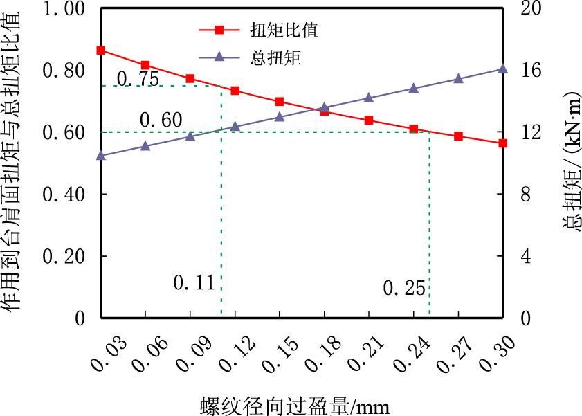 |
| 图6 螺纹牙径向过盈量对总扭矩以及作用到台肩面扭矩与总扭矩比值的影响 Fig. 6 Influences of thread tooth radial interference on the total torque and the ratio of torque acting on shoulder to total torque |
由图 6 可以看出,随螺纹径向过盈量增大,总扭矩呈线性增大,作用到台肩面扭矩与总扭矩比值呈近似线性降低,表明螺纹径向过盈量对总上扣扭矩以及接头密封性能影响很大,为使作用到台肩面扭矩与总扭矩比值控制在0.60∼0.75,螺纹径向过盈量应控制在0.11∼0.25 mm。
3.2 密封面径向过盈量密封面过盈量主要受上扣圈数、密封面锥度以及密封面直径偏差等因素影响。特殊螺纹接头上扣后必须保证密封面之间有足够径向过盈量,从而在密封面产生足够的接触应力分布以保证接头密封性能。以锥面对锥面密封结构为例,计算了密封面径向过盈量在0.10∼0.60 mm 变化时总上扣扭矩、作用到台肩面扭矩与总扭矩比值分布情况,结果如图 7 所示。分析可知:随密封面径向过盈量增大,总扭矩增大,作用到台肩面扭矩与总扭矩比值降低,但总体上二者变化都较小,且密封面过盈量在0.10∼0.60 mm变化时作用到台肩面扭矩与总扭矩比值均处于0.60∼0.75,因此密封面径向过盈量应主要根据接头密封性能对密封面接触应力水平要求确定。
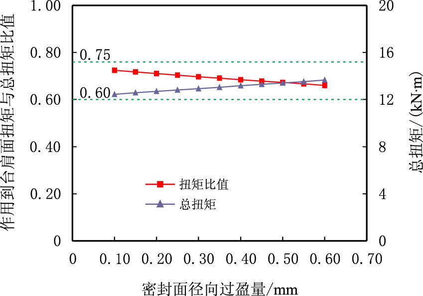 |
| 图7 密封面径向过盈量对总扭矩以及作用到台肩面扭矩与总扭矩比值的影响 Fig. 7 Influences of sealing surface radial interference on the total torque and the ratio of torque acting on shoulder to total torque |
台肩轴向过盈量主要受上扣圈数、尺寸公差等因素影响。图 8 为台肩轴向过盈量在0.005∼0.050 mm 变化时总上扣扭矩、作用到台肩面扭矩与总扭矩比值分布情况。分析可知,随台肩面轴向过盈量增大,总扭矩呈直线增大,作用到台肩面扭矩与总扭矩比值也逐渐增大但增大的速度越来越小。这表明台肩面轴向过盈量对接头总扭矩和密封性能影响均很大。为使作用到台肩面扭矩与总扭矩比值控制在0.60∼0.75,台肩轴向过盈量应控制在0.016∼0.032 mm。同时可以看出,当轴向过盈量足够大时,若继续增大台肩轴向过盈量虽然对台肩扭矩比值影响不大,但总扭矩却大大增加,因而台肩面有屈服风险。因此,应合理控制台肩面尺寸公差和上扣圈数,以保证上扣后台肩面间产生合适的轴向过盈量。
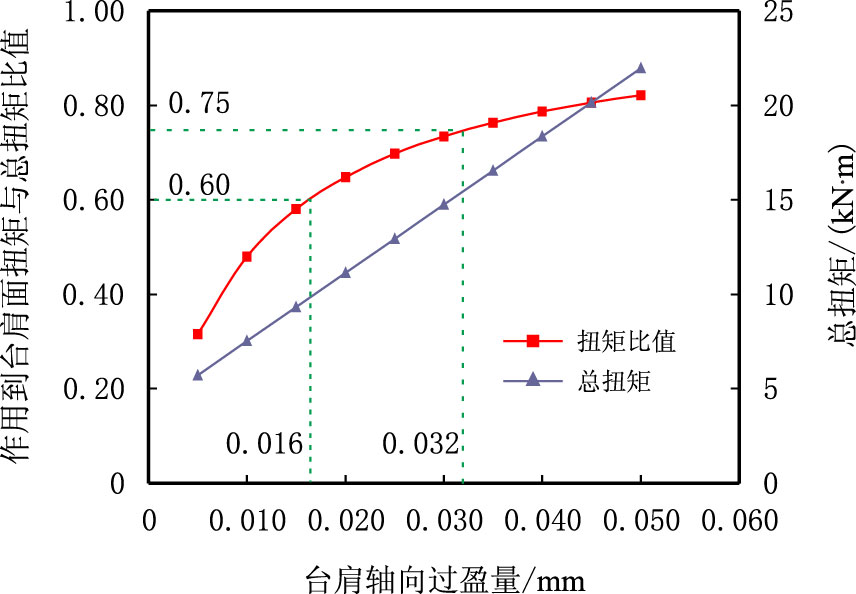 |
| 图8 台肩轴向过盈量对总扭矩以及作用到台肩面扭矩与总扭矩比值的影响 Fig. 8 Influences of shoulder axial interference on the total torque and the ratio of torque acting on shoulder to total torque |
螺纹面间和密封面间摩擦系数主要受表面涂层、表面光洁度以及螺纹脂影响,其中螺纹脂对摩擦系数影响很大。图 9 为螺纹脂摩擦系数在0.04∼0.12 变化时总上扣扭矩、作用到台肩面扭矩与总扭矩比值分布情况。分析可知,随螺纹脂摩擦系数增大,总扭矩呈直线增大,且总扭矩对摩擦系数十分敏感;而作用到台肩面扭矩与总扭矩比值呈直线下降,但该比值总体变化很小,均处于0.60∼0.75。因此应使用合格摩擦系数的螺纹脂,以避免当总上扣扭矩一定时作用到台肩面扭矩不足。
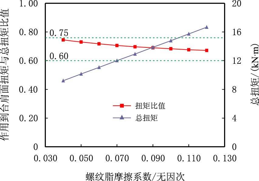 |
| 图9 螺纹脂摩擦系数对总扭矩以及作用到台肩面扭矩与总扭矩比值的影响 Fig. 9 Influences of thread compound friction coefficient on the total torque and the ratio of torque acting on shoulder to total torque |
(1)特殊螺纹接头上扣总扭矩由引扣扭矩、螺纹过盈扭矩、作用到密封面上扭矩和作用到台肩面扭矩4 部分构成。为保证接头密封完整性、避免油套管下入过程发生倒扣,应将作用到台肩面扭矩与总扭矩比值控制在60%∼75%。
(2)特殊螺纹接头总上扣扭矩及其构成主要受螺纹牙径向过盈量和扭矩台肩轴向过盈量控制而受密封面径向过盈量影响小;螺纹脂摩擦系数对作用到台肩面扭矩与总扭矩比值影响不明显,但对总扭矩影响很大。
(3)特殊螺纹接头上扣扭矩及其构成是影响接头连接强度的主要因素之一,建议进一步研究考虑螺纹参数、应力敏感效应的特殊螺纹接头强度理论。
| [1] | Carcagno G. The design of tubing and casing premium connections for HTHP wells[C]. SPE 97584, 2005. |
| [2] | Bradley A B,Nagasaku S,Verger E. Premium connection design, testing, and installation for HPHT sour wells[C]. SPE 97585, 2005. |
| [3] | Sugino M, Nakamura K, Yamaguchi S, et al. Development of an innovative high-performance premium threaded connection for OCTG[C]. OCT 20734, 2010. |
| [4] | International Organization for Standardization(ISO). Petroleum and natural gas industries-procedures for testing casing and tubing connections[C]. ISO 13679:2002. |
| [5] |
解学东, 史交齐, 申昭熙, 等. PSC特殊螺纹接头上扣特性研究[J].
石油机械, 2005, 33 (9) : 12 –15.
Xie Xuedong, Shi Jiaoqi, Shen Zhaoxi, et al. Investigation of makeup performance of premium shouldered connection[J]. China Petroleum Machinery, 2005, 33 (9) : 12 –15. |
| [6] |
王新虎, 申照熙, 王建东, 等. 特殊螺纹油管与套管的上扣扭矩构成与密封性能研究[J].
石油矿场机械, 2010, 39 (12) : 45 –50.
Wang Xinhu, Shen Zhaoxi, Wang Jiandong, et al. Study on the makeup torque constitutes and seal integrity of tubing and casing premium connection[J]. Oil Field Equipment, 2010, 39 (12) : 45 –50. |
| [7] | Murtagian G R, Fanelli V, Villasante J A, et al. Sealability of stationary metal to metal seal[J]. Journal of Tribology, 2004, 126 (3) : 591 –596. DOI:10.1115/1.1715103 |
| [8] |
吴稀勇, 闫龙, 陈涛. 特殊螺纹接头扭矩的分析[J].
焊管, 2010, 33 (9) : 12 –14.
Wu Xiyong, Yan Long, Chen Tao. Analysis on torque of premium connections[J]. Welded Pipe and Tube, 2010, 33 (9) : 12 –14. |
| [9] |
杨智春, 李斌, 史交齐. 特殊扣套管接头的应力及密封特性分析[J].
机械科学与技术, 2004, 23 (7) : 771 –773.
Yang Zhichun, Li Bin, Shi Jiaoqi. Stress and sealing property analysis of premium threaded connection[J]. Mechanical Science and Technology, 2004, 23 (7) : 771 –773. |
| [10] | Xie Jueren. Analysis of strain rate impact on make-up of oilfield premium casing connections[C]. SIMULIA Customer Conference, 2011. |
| [11] | 徐芝纶. 弹性力学[M]. 北京: 高等教育出版社, 2004 . |
| [12] | American Petroleum Institute (API). Recommended practice for drill stem design and operating limits[C]. API RP 7G:16(E), 1998. |
| [13] | American Petroleum Institute (API). Specification for threading, gauging, and thread inspection of casing, tubing,and line pipe threads[C]. API Spec 5B:15(E),2008. |
 2014, Vol. 26

