2. Xi’an University of Technology, School of Automation and Information Engineering, Xi’an 710048, China
2. 西安理工大学 自动化与信息工程学院,西安 710048
Various modern aircrafts such as airplanes and missiles are usually designed with a slender body shape to pursue drag reduction, and these aircrafts are also required to fly at high angles of attack and even for post stall due to the maneuverability requirements. However, as the angle of attack increases, the flow filed around such a slender body may exhibit a complex phenomenon, resulting that the aerodynamic forces and moments become unsteady and non-linear with the angle of attack, eventually leading to an unpredictable lateral force and moment[1]. The asymmetric vortices, which are formed in the leeward region of the slender body with different strengths and positions[2], are responsible for the random lateral forces whose directions and magnitudes are unpredictable. It has been found that asymmetric vortices are very sensitive to small perturbations near the apex of the forebody[2-3], which indicates an opportunity for manipulating these vortices with little input energy to achieve active lateral control. Malcolm[4] and Williams[5] have studied and summarized different flow control methods towards lateral control such as various deployable mechanical devices, blowing and suction, etc. However, most of these control methods are based on steady methods.
In 2008, Liu et al.[6] firstly proposed nearly linear proportional control of lateral forces and moments by dielectric barrier discharge (DBD) plasma s with a duty-cycle technique. Since then, plasma control of lateral forces has drawn more attention. Following related researches are mainly concentrated on different configurations of DBD plasma actuators and electrical parameters to improve its control efficiency[7-10]. As an active flow control device, the DBD plasma actuator has a great potential in flow control due to its many unique advantages, including fast-acting, no moving mechanical parts, low power consumption, etc. Many studies have revealed the effectiveness of DBD plasma actuators for boundary layer control[11-14], aircraft noise reduction[15-16], vortex shedding control[17-18] and control of lateral aerodynamic forces on slender bodies[6, 8] among others.
Typically, a conventional DBD plasma actuator consists of two electrodes separated by a dielectric layer, with one electrode completely encapsulated in the dielectric layer and the other exposed. Upon application of a high-voltage and high-frequency alternating current (AC) power source, the air surrounding the exposed electrode becomes ionized, and plasma is formed. The plasma produces a body force on the ambient air in the presence of the electric field, and the body force accelerates the surrounding air to form a wall jet. Although many studies have confirmed the ability of DBD plasma actuators in flow control, there are still many researches on the optimization of DBD plasma actuators to further promote the ability in flow control. The thrust generated by DBD plasma actuators is considered as a key factor for flow control, which is related to many factors, such as the geometric configuration of the DBD plasma actuator, the dielectric layer material, the peak-to-peak voltage, frequency and so on. A wire-based DBD plasma actuator, whose exposed electrode is steel wire with a small diameter, has been proposed and verified by Enloe[19] and Hoskinson[20], and it can produce much larger thrust and is likely more efficient in flow control than that of the conventional configuration of plasma actuators. However, according to authors’ knowledge, there is only few studies concentrating on the application of flow control with wire-based DBD plasma actuators due to the special structure and some other difficulties. The purpose of this paper is to apply the wire-based DBD plasma actuator to the forebody vortex control for the first time, which provides a feasible method for the application of wire-based DBD plasma actuator in the future.
As mentioned above, not many literatures have studied the plasma actuator with an exposed wire-based electrode yet, though it can generate larger thrust than that of conventional DBD; also, few researches have applied this kind of plasma actuator for actual flow control, especially for the forebody vortex control. In this paper, for the first time, the wire-based DBD plasma actuator is applied to the forebody vortex control at high angles of attack. The thrust generated by wire-based DBD plasma actuators in quiescent air is firstly studied in section 1, with the goal to design an optimal configuration of the wire-based DBD plasma actuator; section 2 provides the wind tunnel test for the forebody vortex control with wire-based DBD plasma actuators under the optimal configuration; and finally conclusions are given in section 3.
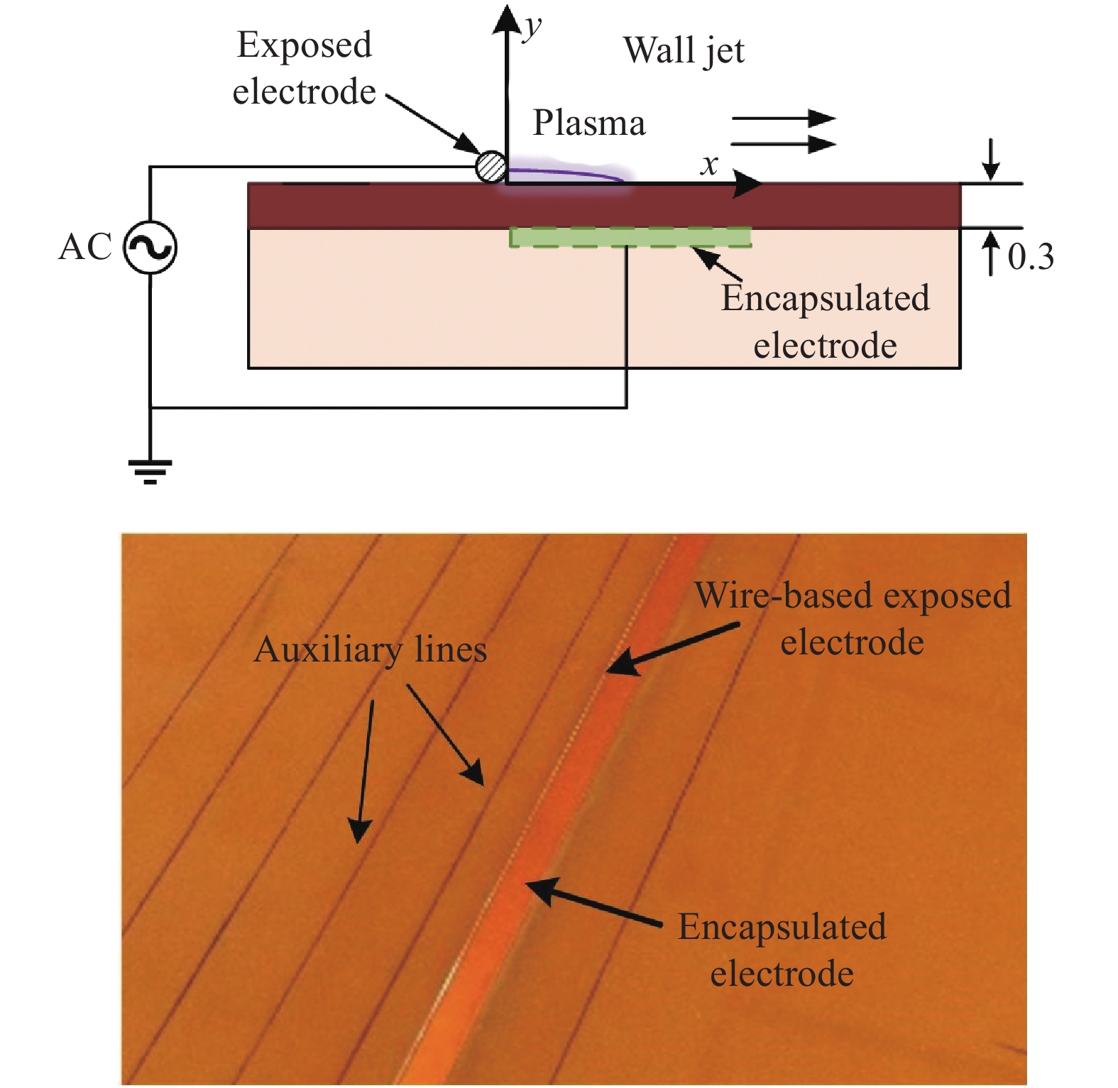
1 Thrust measurement of wire-based DBD plasma actuators 1.1 Experimental setupThe wire-based DBD plasma actuator used in the present study, as shown in Fig.1, consists of an exposed wire-based electrode and a 0.066-mm-thick copper encapsulated electrode (3M EMI Copper Foil Shielding Tape 1181) separated by a 0.3-mm-thick layer (three layers incorporated) of Kapton. The dielectric constant of Kapton is 3.2. The effective spanwise length is 200 mm. The width of the encapsulated electrode is 4 mm, and the diameter of the exposed electrode d will be given in detailed experiments. The exposed wire-based electrode is connected to a high-voltage AC power source CTP-2000K (Vp-p: 0~30 kV; frequency: 5~20 kHz) manufactured by Corona Lab, while the encapsulated electrode is connected to the ground. The voltage and current are measured by a high-voltage probe (P6015A, Tektronix) and a current probe (TCP0030A, Tektronix), respectively. The voltage probe and current probe are monitored and recorded by an oscilloscope (MDO4104, Tektronix) to evaluate the power consumption.
|
Fig.1 Schematic and physical display of the wire-based DBD plasma actuator 图 1 丝状电极等离子体激励器示意图 |
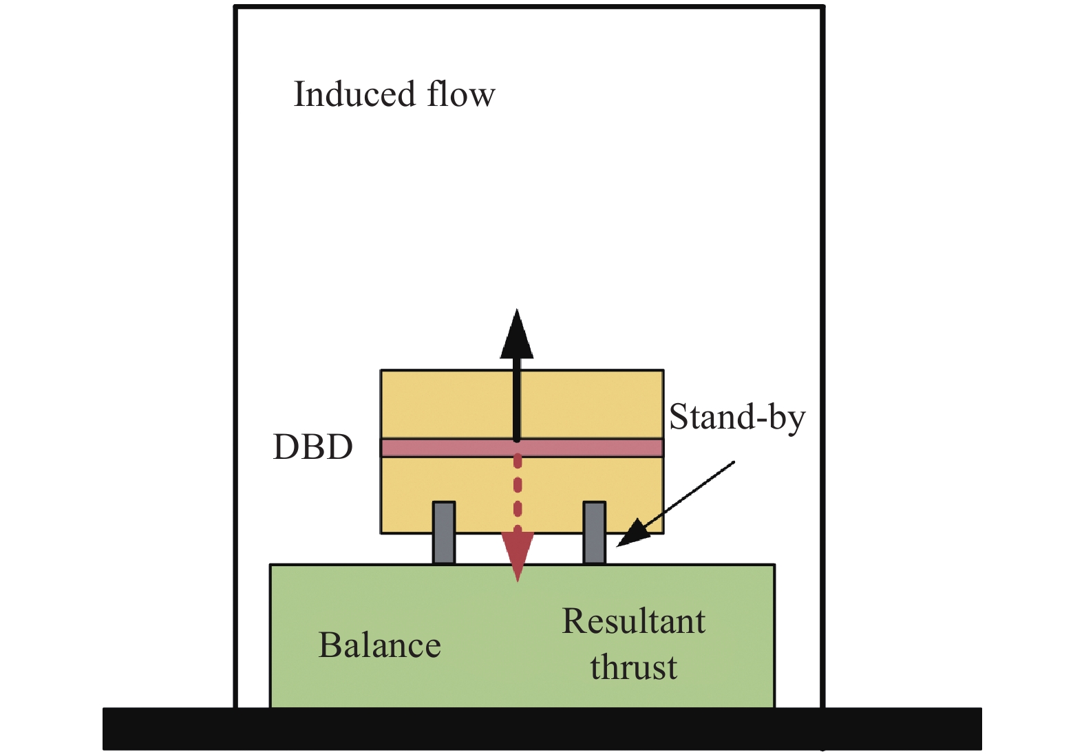
The experimental setup is shown in Fig. 2, where an electronic balance is used to measure the thrust generated by the DBD plasma actuator. When the actuator is in operation, a resultant thrust, which is induced by the upward wall jet, is approximately equal to the thrust generated by the actuator. The maximum range of the balance is 500 grams, and the accuracy is 0.001 grams (appropriate 0.098 mN). To ensure that the measured thrust is reliable, the balance is placed horizontally to make sure that the direction of wall jet is in alignment with the vertical direction. A wire (Nickel alloy, NiCr) with a diameter of 0.08 mm is used to connect the AC power supply and the DBD plasma actuator. The entire device is placed in a glass box to ensure that the experimental results are not affected by the external environment.
|
Fig.2 Experiment setup of the thrust measurement 图 2 DBD推力测量试验装置 |
The procedure of the thrust measurement is as follows: (1) Before the starts, the reading of the balance is reset to zero and this reading value does not change with time; (2) When the DBD plasma actuator is in operation, the reading value of the balance fluctuates and eventually stabilizes after a period of time (approximately about ten seconds according to the tests, and a period of more than 20 seconds is adopted for the thrust measurement), corresponding to the thrust produced by the DBD plasma actuator. It is found that the electronic balance is extremely susceptible to electromagnetic interference during tests. As shown in table 1, when the electronic balance is not electromagnetically shielded, the maximum difference between the thrusts measured before and after is up to 0.026 g. After the balance is electromagnetic shielded, as shown in Fig. 3, the maximum value difference is reduced, but still up to 0.007 g as shown in table 1. It is found that the electric balance not only needs to be electromagnetic shielded but also needs to be connected to an UPS (Uninterruptible Power Supply), which is separated from the high-frequency and high-voltage AC plasma power supply. Under the third measuring condition, the thrust measured before and after is nearly zero as shown in table 1.
| Table 1 The thrust measured for the balance under three different conditions 表 1 在三种不同条件下天平测得的推力 |
|
|

|
Fig.3 Electronic balance with the electromagnetic shield 图 3 电磁屏蔽后的电子天平 |
In order to analyze the thrust efficiency of the wire-based DBD plasma actuator with different diameters and different materials of the exposed electrode, the voltage and current are also measured by probes to evaluate the power consumption as mentioned in the experimental setup. The power consumed by the DBD plasma actuator can be calculated as follows:
| ${P_a}\left( t \right) = {V_a}\left( t \right) \cdot {I_a}\left( t \right)$ | (1) |
where V(t) is the peak-to-peak voltage, I(t) the current, and the subscript a indicates a sinusoidal period. The total power consumed by the DBD plasma actuator is:
| $ \overline{{P}_{a}}=\frac{1}{T}{\int }_{0}^{T}{V}_{a}\left(t\right)\cdot {I}_{a}\left(t\right){\rm{d}}t $ | (2) |
Here, T represents a period of the sinusoidal AC. To ensure the accuracy of the calculated power, The voltage and current over several periods are measured. The averaged power consumption in n (about 10~15) periods can be calculated by:
| $ \overline{{P}_{a}}=\frac{1}{nT}{\int }_{{t}_{0}}^{{t}_{n}}{V}_{a}\left(t\right)\cdot {I}_{a}\left(t\right){\rm{d}}t $ | (3) |
Figure 4 shows the waveforms of the voltage and current under the application of Vp-p = 14 kV, F = 8 kHz, with the blue and orange curves are the peak-to-peak voltage and the current, respectively. It should be noted that Figure 4 only shows the waveforms within 20 ms, and the actual data recording time is about 300 ms. According to the above calculation method, the power consumption for this case, as shown in Fig. 4, is about 46.68 W.

|
Fig.4 Waveforms of the voltage and current with Vp-p = 14 kV, F = 8 kHz. The exposed electrode is a 0.08 mm tungsten wire 图 4 Vp-p = 14 kV, F = 8 kHz时电流电压波形图,暴露电极为钨丝,直径为0.08 mm |
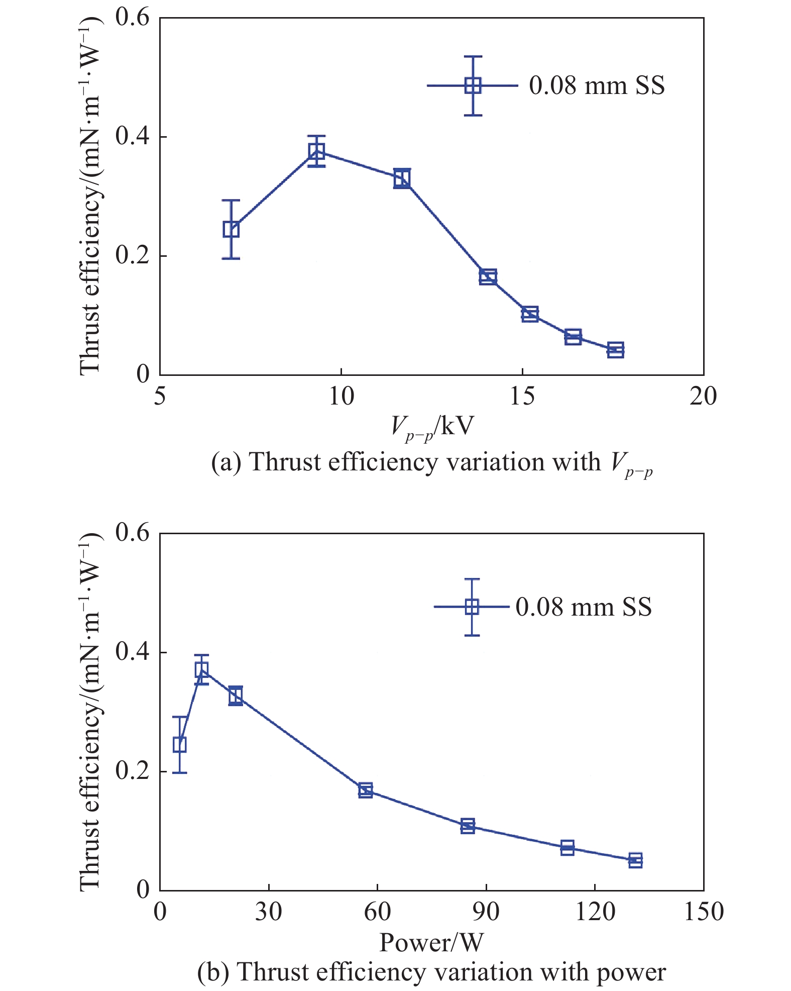
The characteristics of the thrust generated by the DBD plasma actuator are firstly studied within this section. Here, the wire-based electrode used is a 0.08 mm-diameter stainless steel wire. Fig. 5(a) shows the magnitude of the thrust generated by the DBD plasma actuator varies with the peak-to-peak voltage Vp-p, which is consistent with other published results[21]. It is noted that the thrust plotted in all figures has the unit of “mN/m”, and its physical meaning is the thrust generated by the DBD plasma actuator with a unit spanwise length. As mentioned before, the effective spanwise length of the DBD plasma actuator is 200 mm. It can be seen that the thrust increases as Vp-p increases from 8 kV to 14 kV, and slightly decreases as Vp-p > 15 kV. Such a trend has been verified by repeating our experiments for three times, but it is very different from the results by Enloe [19] and Kotsonis et al.[21], who reported that the thrust increased monotonically with the increase of the peak-to-peak voltage. This is because of different discharge characte-ristics due to the electrical parameters such as the frequency and the peak-to-peak voltage. It is noticed that a lower peak-to-peak voltage ranging from 3 kV to 8 kV was selected by Enloe[19], and a frequency less than 4 kHz was selected by Kotsonis et al.[21]. In both experiments, the voltage did not reach the saturation value, above which (14 kV in present experiment) the plasma length and strength do not change any more[22]. The power consumed by the DBD plasma actuator with different peak-to-peak voltages is shown in Fig. 5(b), where the consumed power gradually increases with the increase of the peak-to-peak voltage. The thrust efficiency, which represents the thrust generated by the DBD plasma actuator with unit energy dissipated, is shown in Fig. 6. With the increase of Vp-p, the efficiency of the thrust increases, then decreases, and it reaches the maximum at about Vp-p = 10 kV. The power consumed by the DBD plasma actuator gradually increases with the increase of Vp-p, but the thrust does not increase all the time but decreases when Vp-p exceeds a definite value, resulting in that the thrust efficiency gradually decreases.

|
Fig.5 Thrust and dissipated power variation with peak to peak voltage Vp-p 图 5 推力和功率随峰峰电压变化曲线 |
|
Fig.6 Thrust efficiency as a function of Vp-p and dissipated power 图 6 推力效率随峰峰电压和功率的变化曲线 |
It should be noted that during the experiment, the dielectric layer can break down with the increase of Vp-p, and the DBD plasma actuator will be irreversibly damaged and cannot be used for a long time. For this reason, Vp-p = 14 kV is adopted as the maximum voltage in the following study.
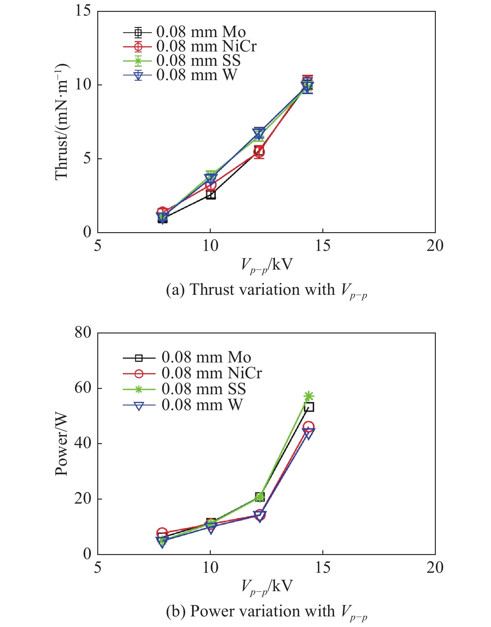
The thrust of the DBD plasma actuator with different materials of the exposed wire-based electrode is measured and shown in Figure 7. The diameter of the exposed electrode is 0.08 mm, and the materials of the exposed electrode includes molybdenum (Mo), nichrome alloy (NiCr), stainless steel (SS) and tungsten (W). Figure 7 shows the thrust generated by the DBD plasma actuator and the dissipated power as a function of Vp-p for different materials of the exposed electrode. With the increase of the peak-to-peak voltage, the thrust generated by the DBD plasma actuator increases. The materials of the exposed wire-based electrode have little effect on the thrust, as shown in Fig. 7(a), but the thrust generated by electrodes of SS and W is slightly larger than that of Mo and NiCr at Vp-p = 10 kV and Vp-p = 12 kV. With the increase of Vp-p, the dissipated power increases slightly for Vp-p < 12 kV, but sharply for Vp-p > 12 kV, as shown in Fig. 7(b). Moreover, when Vp-p ≤ 10 kV, it seems that the dissipated power of the DBD plasma actuator is independent of materials of the exposed wire-based electrode. However, when using tungsten (W) or nickel complex alloy (NiCr) for the exposed wire-based electrode, the power consumption is lower than that of stainless steel (SS) or molybdenum (Mo). This is probably caused by the electrical property of different materials.
|
Fig.7 Thrust and dissipated power variation with peak to peak voltage Vp-p for different materials of the exposed electrode, d = 0.08 mm 图 7 不同电极材料时,推力和功率随峰峰电压的变化曲线,电极直径为0.08 mm |
For different exposed electrode materials, although both the thrust generated and the power consumed are not greatly affected by the material, it is found that the thrust efficiency can be largely affected by the material. Figure 8 shows the thrust efficiency as a function of Vp-p and the dissipated power with different materials of the exposed electrode. As the peak-to-peak voltage increases, the thrust efficiency increases, then decreases, reaching the maximum at about Vp-p = 12 kV. It can be seen that the material of the exposed electrode has a great impact on the thrust efficiency of the DBD plasma actuator. The thrust efficiency of the DBD plasma actuator with tungsten (W) made exposed electrode is apparently larger than that with other materials including NiCr, Mo and SS, even up to nearly 94% larger than that of Mo at Vp-p = 12 kV as shown in Fig. 8(a). Similarly, as the power consumption increases, the thrust efficiency increases, then decreases, as shown in Fig. 8(b), indicating that increasing the consumed power cannot promote the thrust efficiency of the DBD plasma actuator. Anyway, it can be found from Fig. 8 that when the exposed electrode is made from tungsten, the thrust efficiency of the DBD plasma actuator is the highest for a given Vp-p and power consumption among the materials presented.

|
Fig.8 Thrust efficiency variation with peak to peak voltage Vp-p and dissipated power for different materials of the exposed electrode, d = 0.08 mm 图 8 不同电极材料时,推力效率随峰峰电压和功率的变化曲线,电极直径为0.08 mm |
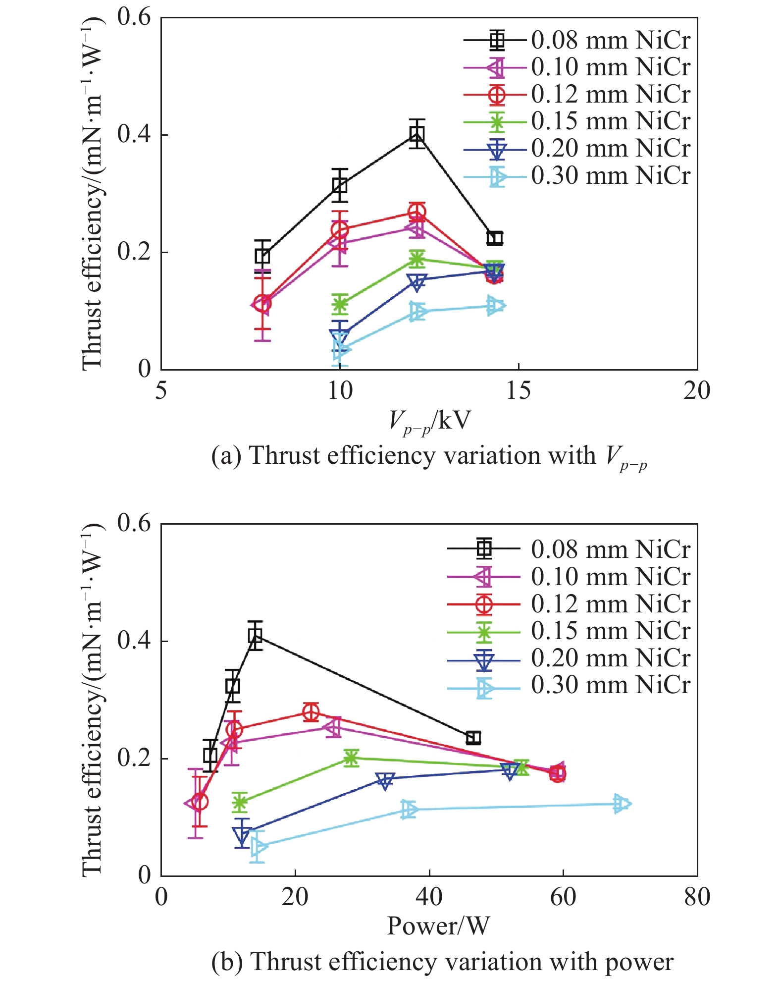
In order to study the effect of exposed electrode’s diameter on thrust generated by the DBD plasma actuator, the steel wire made from NiCr and with a diameter d, ranging from 0.08 to 0.3 mm is adopted as the exposed wire-based electrode. From Fig. 9(a), it can be clearly seen that as the exposed electrode diameter decreases, the thrust generated by the DBD plasma actuator increases. The thrust for the actuator with a diameter of the exposed electrode d = 0.3 mm is significantly less than that with d = 0.08 mm. However, the power consumption of the actuator with d = 0.3 mm is obviously greater than that with d = 0.08 mm, as shown in Fig. 9(b). As the diameter of the exposed electrode increases, the thrust generated by the DBD plasma actuator decreases, while the power consumed increases. This results in a significant difference in the thrust efficiency of DBD plasma actuators with different diameters of the exposed electrode. The thrust efficiency as a function of Vp-p and the dissipated power is plotted in Figs. 10(a) and (b), respectively. As mentioned before, with the increase of Vp-p, the thrust efficiency of the DBD plasma actuator increases then decreases, and it is especially obvious when d ≤ 0.15 mm, where the thrust efficiency reaches the maximum at about Vp-p = 12 kV. It can be found that the thrust efficiency of the DBD plasma actuator with exposed electrode’s diameter d = 0.08 mm is much higher than that of d = 0.3 mm. More importantly, with the reduction of the diameter of the exposed electrode from d = 0.3 mm to d = 0.08 mm, the thrust efficiency increases significantly.

|
Fig.9 Thrust and dissipated power variation with peak to peak voltage Vp-p for for different diameters of the exposed electrode of NiCr 图 9 不同电极直径时,推力和功率随峰峰电压的变化曲线,电极材料为NiCr |
|
Fig.10 Thrust efficiency of the DBD plasma actuator as a function of Vp-p and dissipated power for different diameters of the exposed electrode of NiCr 图 10 不同电极直径时,推力效率随峰峰电压和功率的变化曲线,电极材料为NiCr |
In conclusion, both the diameter and the material of the exposed electrode are very important for the optimization of the wire-based DBD plasma actuator, especially for the thrust efficiency, thus it is of great significance to improve the plasma flow control effect by selecting the appropriate diameter and material of the exposed electrode.
2 Forebody vortex control with wire-based DBD plasma actuatorsHere, we use the optimal configuration of the wire-based DBD plasma actuator from the previous study that the material and diameter of the exposed wire-based electrode is tungsten and 0.08 mm, respectively, for the forebody vortex control in wind tunnel tests for the first time. Both surface pressure measurement and PIV technique are conducted to analyze the effect of asymmetric vortex control.
2.1 Model and experimental setupExperiments are conducted in a low-speed wind tunnel at the Air Force Engineering University. The test section of the wind tunnel is 1.0 m×1.2 m×1.0 m. The maximum speed of the freestream is U∞ = 75 m/s with a turbulence level of ε ≤ 0.2%. The slender body model, as shown in Fig. 11, consists of a cone and a cylindrical segment with a total length of L = 600 mm. The base diameter is D = 120 mm, and the semi-apex angle is 10°. The whole model is made from epoxy resin. Two plasma actuators are placed symmetrically along the line of azimuth angles of θ = 90° and −90° near the cone apex, and installed on the detachable head with a total length 150 mm, as shown by the blue region in Fig. 11. The effective discharge length is 100 mm. The buried electrode is 0.03 mm-thick copper foil tape, and the dielectric layer is a three-layer polyimide film with a thickness of about 0.3 mm. The exposed electrode is a 0.08 mm tungsten wire. The entire wire-based DBD plasma actuator is carefully handled on the detachable head to ensure that the surface of the model is smooth.

|
Fig.11 Schematic of the slender body model 图 11 细长体模型示意图 |
Surface pressure is measured by pressure transducers PSI 9816, which have an accuracy within 0.1% full scale, to analyze the flow control effect of the wire-based DBD plasma actuator. Four pressure measurement stations are mounted on the model at intervals of 20 mm along the middle axis. Twenty-four pressure taps are circumferentially distributed at each station at azimuth angle intervals of 15°. The sampling frequency is 100 Hz and the pressure of consecutive 10 s is recorded for time averaged analysis. Also, the flow field at section 1, where is the first section in pressure measurements, is obtained by the TSI PIV system, which consists of a Nd:YAG Laser, produced by the Beamtech Optronics Co., with a single pulse of energy ≤ 200 mJ, and A CCD camera of 2048×2048 pixels. The Laser sheet is 1mm thickness. The time interval of double pulses is set to be 80 μs. The sampling frequency is set at 7 Hz. A 32×32 pixels rectangular interrogation window with a 75% overlap is adopted to analyze the experimental data to acquire more precise spatial resolution. Facing the freestream, the right side of the cone is defined as the starboard side, and the left side is defined as the port side. The middle of the windward side corresponds to an azimuth angle of θ = 0°, and the counterclockwise direction is defined as the positive direction. The slender body model mounted in the wind tunnel is shown in Fig. 12, and the discharge pattern of DBD plasma actuator is shown in Fig. 12. Here, it should be mentioned that the pressure sensors are outside the wind tunnel and very far away from the DBD plasma actuators in pressure measurements, and the camera and other devices are placed outside the wind tunnel in PIV measurements as well. The electromagnetic effects on pressure and PIV measurements are believed to be negligible in the present experimental setup.

|
Fig.12 The slender body model mounted in the wind tunnel and the discharge pattern of wire-based DBD plasma actuators 图 12 细长体模型在风洞安装示意图及丝状电极等离子体激励器放电图像 |
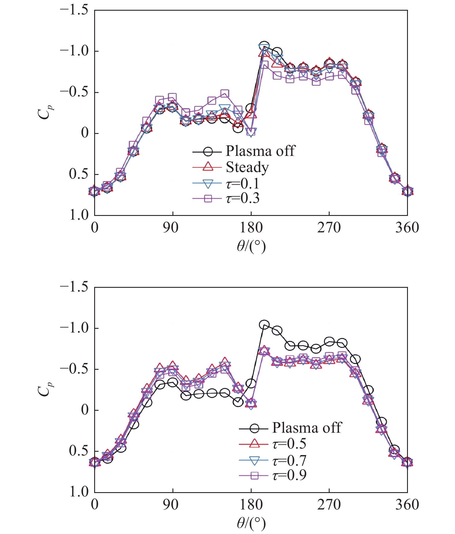
Forebody vortex control with DBD plasma actuators of wire-based electrodes is studied in this section. The slender body model is tested at α = 45° and U∞ = 10 m/s, with a Reynolds number (based on the cone base diameter) of 0.75×10⁵. Although the asymmetric vortices of the forebody is very sensitive to small disturbances of the surface, in this experiment, only the effects of “plasma off” and “plasma on” on the asymmetric vortex are compared, regardless of the effect of the wire-based DBD plasma actuator on the surface of the slender body model. Figures 13~15 show the time-averaged surface pressure distributions at test section 1 (x/L = 0.25) for Vp-p = 8 kV, 10 kV and 12 kV, respectively. Duty ratio of τ = 0.1~ 0.9 represents the burst-mode with a duty cycle from 10% to 90%, whereas steady (τ = 0) represents continuous plasma . Both the steady operation and the burst-mode with the same voltage and frequency of AC power source are studied. Here, the burst frequency is f = 450 Hz. It should be mentioned that is activated on both sides simultaneously (Port on and Starboard on). As can be seen in Fig. 13, when plasma actuator is off, the pressure distribution shows that the suction peak on the right side is higher than that on the left side, indicating that the vortex core on the right side is closer to the surface of the model than that on the left side. At Vp-p = 8 kV, the pressure distribution already presents an obvious asymmetric vortex structure under the steady operation. However, when the duty ratio gradually increases from τ = 0.1 to τ = 0.9 under the burst-mode , the suction peak increases on the left while decreases on the right, indicating that the asymmetric vortex gradually becomes more symmetry under the control.
|
Fig.13 Pressure distribution under steady operation and burst-mode actuation, Vp-p = 8 kV, F = 8 kHz, f = 450 Hz for the burst-mode actuation 图 13 等离子体激励时细长体表面压力分布,Vp-p = 8 kV, F= 8 kHz, f = 450 Hz |
|
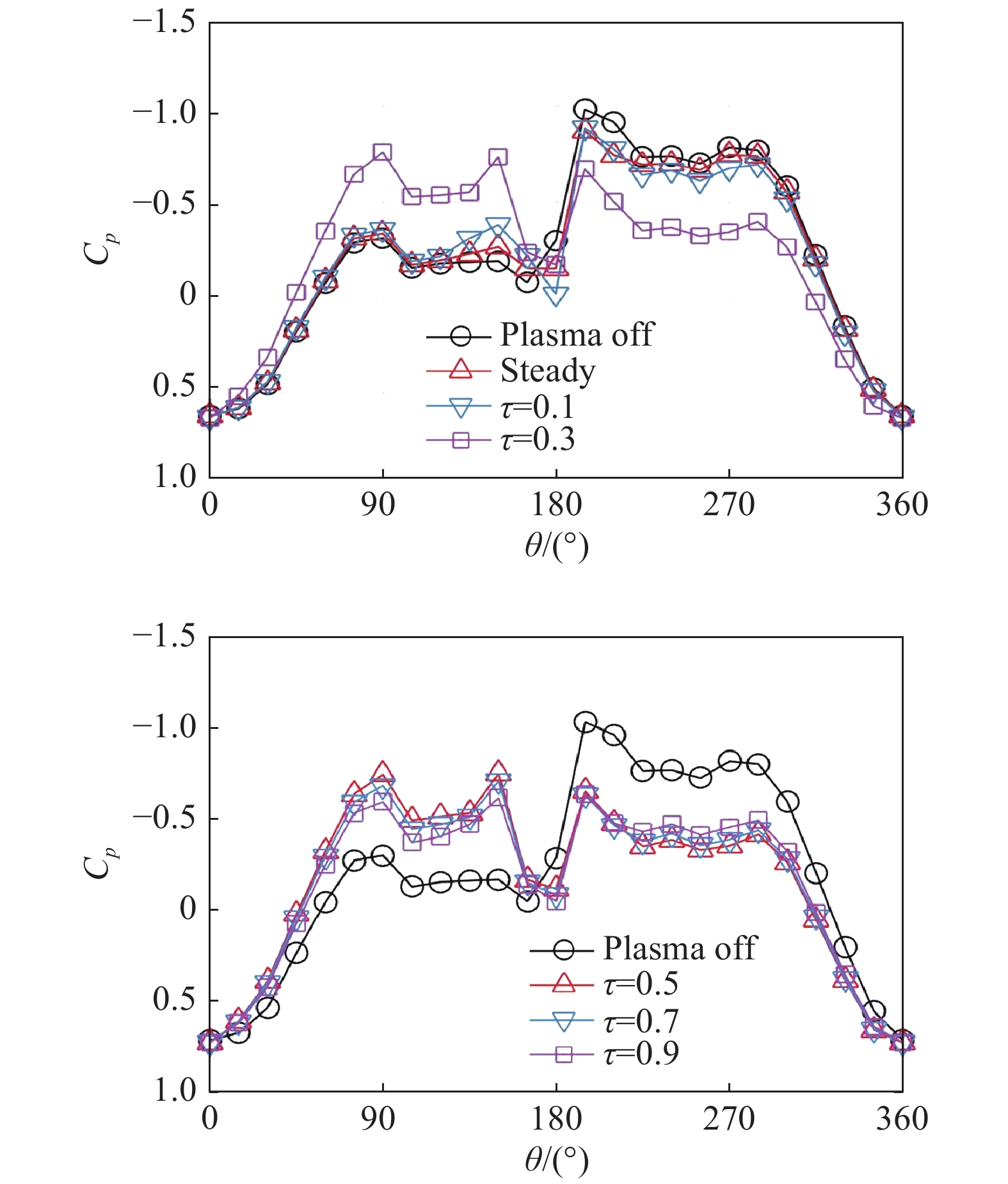
Fig.14 Pressure distribution under steady operation and burst-mode actuation, Vp-p = 10 kV, F = 8 kHz, f = 450 Hz for the burst-mode actuation 图 14 等离子体激励时细长体表面压力分布,Vp-p = 10 kV, F = 8 kHz, f = 450 Hz |
|
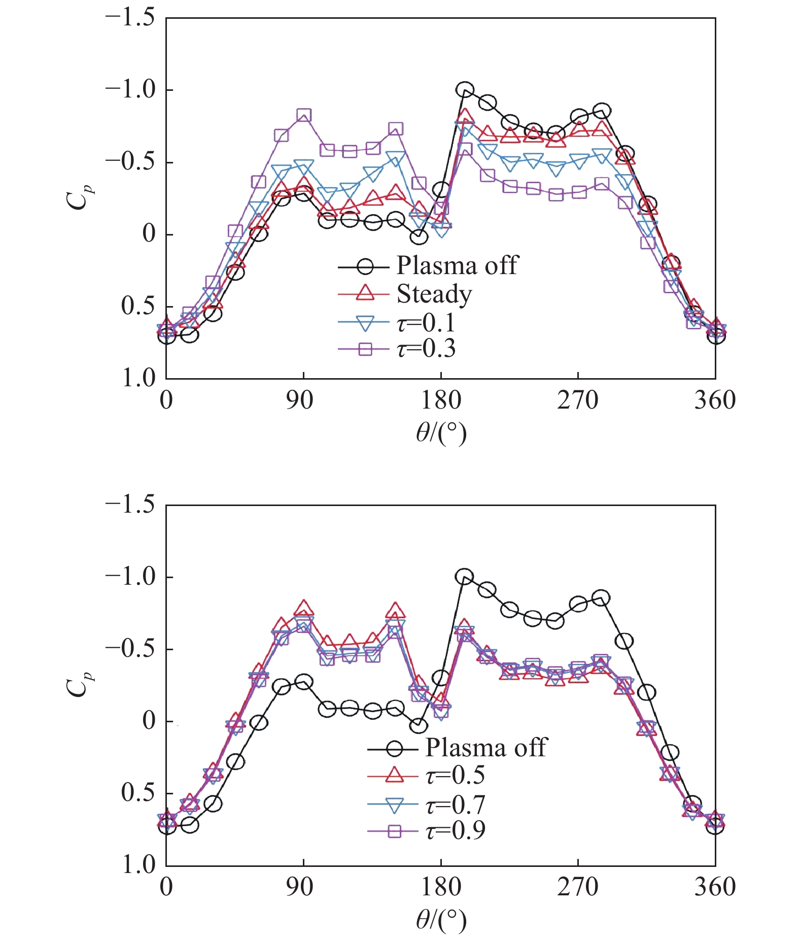
Fig.15 Pressure distribution under steady operation and burst-mode actuation, Vp-p = 12 kV, F = 8 kHz, f = 450 Hz for the burst-mode actuation 图 15 等离子体激励时细长体表面压力分布,Vp-p = 12 kV, F = 8 kHz, f = 450 Hz |
When the peak-to-peak voltage gradually increases from Vp-p = 8 kV to Vp-p = 10 kV, as shown in Fig. 14, the plasma under the steady operation cannot obviously change the pressure distribution. With the increase of the duty cycle from τ = 0.1 to τ = 0.9 under the burst-mode , the suction peak on the left increases, while that on the right decreases, resulting in that the suction peak on the left is even slightly higher than that on the right (τ=0.3~0.9). This result is similar to that of Vp-p = 8 kV (Fig. 13), and also verified when the peak-to-peak voltage increases to Vp-p = 12 kV as shown in Fig. 15. it is found that with the increase of Vp-p, the ability of plasma flow control on the forebody vortex is further improved especially when Vp-p = 12 kV, even with a duty cycle τ = 0.1, which can be seen from the pressure distribution, as shown in Fig. 15, that the asymmetric vortex becomes more symmetrical.
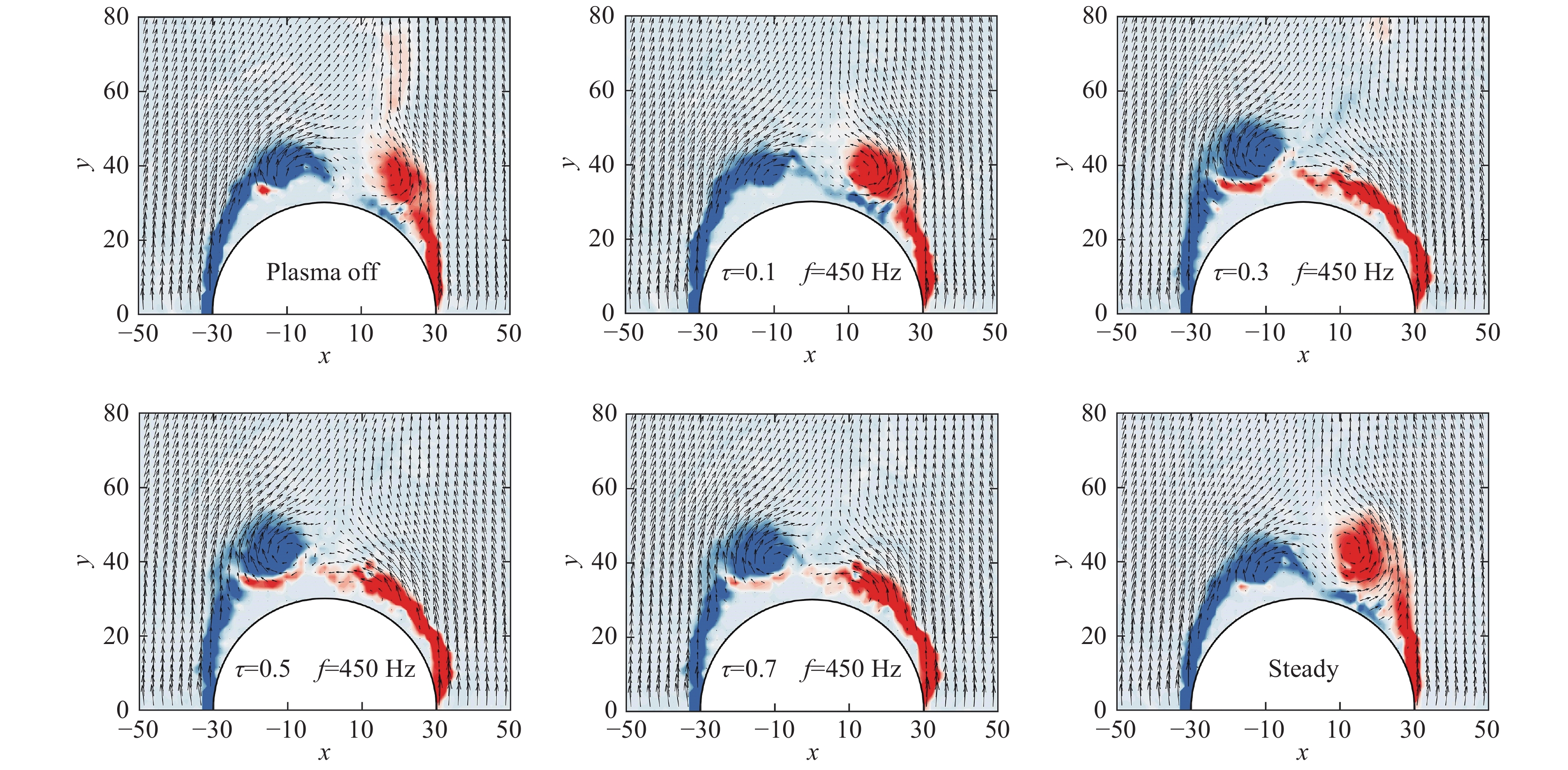
Figure 16 shows the averaged velocity vector and vorticity contour measured by PIV when the plasma flow control is applied. Here, the input electric parameters are Vp-p = 12 kV and F = 8 kHz, corresponding to that of Fig. 15. Compared with the case “plasma off”, with the duty cycle increasing from τ = 0.1 to τ = 0.3, the right vortex gradually moves towards the wall, while the left vortex gradually moves away from the wall. The corresponding pressure distribution is shown in Fig. 15, where the right suction peak decreases and the left suction peak increases. When the duty cycle further increases from τ = 0.3 to 0.7, the pressure distribution and PIV results are minimally affected, indicating that the control ability is not obvious as the input energy increases. The flow pattern of τ = 0.9 is similar to that of τ = 0.7 and is not presented here. When the plasma actuator is operated in continuous mode, namely “steady”, the flow control effect does not improve but returns to the original asymmetric flow state, which is an intermediate state between the cases “plasma-off” and “τ = 0.1”. It should be noted that although the DBD plasma actuator is in unsteady operation (burst-mode ), the flow field of the forebody shows a “steady” state, which means that it is an averaged flow field rather than an instantaneous one[10, 23].
|
Fig.16 The velocity vector and vorticity contour, Vp-p = 12 kV, F = 8 kHz, f = 450 Hz for the burst-mode actuation 图 16 不同占空比时速度矢量及涡量云图,Vp-p = 12 kV, F = 8 kHz, f = 450 Hz |
It is found that the plasma under the burst-mode is more efficient on the forebody vortex control than that under the steady operation according to Fig. 13 to Fig. 16. The electrical parameter is important especially for the burst-mode. Corke and Post[24] reported that the power consumption for a 10% duty cycle ratio was approximately 10% of that with the steady operation, and the power consumption increased linearly with the duty cycle. As shown in Fig. 13 to Fig. 15, with the increase of the duty cycle from τ = 0.1 to τ = 0.9 under the burst-mode, the suction peak on the left increases while that on the right decreases. However, the pressure distribution of τ = 0.5 ~ 0.9 seems to lie almost on top of each other, indicating that with the increase of the duty cycle in that regime, the control ability is not prompted but with more power consumption.
Figure 17 shows the pressure distribution on the surface of the slender body with different pulse frequencies at Vp-p = 12 kV, F = 8 kHz, where the duty cycle is fixed as τ = 0.5. It can be seen that the pressure distribution still shows an obvious asymmetric vortex structure under steady operation and burst-mode with low burst frequencies f ≤ 60 Hz. As the burst frequency gradually increases from f =10 Hz to f = 450 Hz, the suction peak on the left side increases, while that on the right side decreases. The pressure distribution at f = 450 Hz is nearly mirror symmetric with respect to the pressure distribution in the case of plasma off. However, with further increase of the burst frequency from f = 450 Hz to f = 1200 Hz, the suction peak on the left side decreases, while that on the right side increases, indicating that the control effect decreases.

|
Fig.17 Pressure distribution under steady operation and burst-mode actuation, Vp-p = 12 kV, F = 8 kHz, τ = 0.5 for the burst-mode actuation 图 17 脉冲频率对细长体表面压力分布的影响,Vp-p = 12 kV, F = 8 kHz, τ = 0.5 |
The influence of the burst frequency on the forebody vortex control is mainly due to a series of small-scale vortices generated by the DBD plasma actuator under the burst-mode , which can enhance the momentum exchange between the boundary layer and the main flow, making the flow less susceptible to separation.
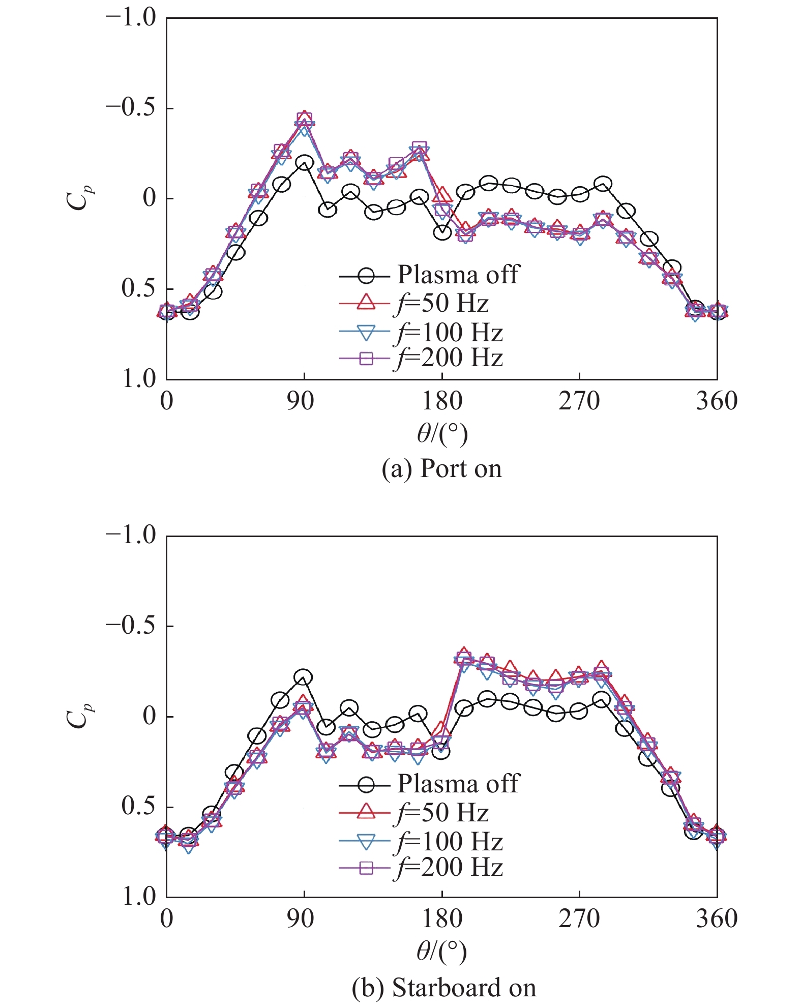
In experiments, it is found that the control effect also depends on the forebody vortex structure itself, as this structure can be either symmetric or asymmetric in the leeward zone of the forebody according to the Reynolds number at a fixed angle of attack. Fig. 18 shows the pressure distribution when a symmetrical vortex structure is formed in the leeward zone at Re = 0.45×10⁵. It can be clearly seen that when the plasma control is applied only on the left side, which is named “port on” as shown in Fig. 18(a), the suction peak on the left side is significantly increased, while the suction peak on the right side is significantly reduced. On the contrary, when the plasma control is applied only on the right side, named “starboard on” as shown in Fig. 18(b), the pressure distribution is nearly mirror to that of “port on”. The averaged flow field from the PIV measurement is shown in Fig. 19. A nearly symmetrical vortex structure is formed when the plasma is off, which is consistent with the vortex structure derived from the pressure distribution. When the plasma flow control is only applied to the left side, namely “port on” as shown in Fig. 19(b), a positive momentum is injected into the flow field on the left side, causing the separation point to be delayed and an asymmetric vortex structure is formed instead of a symmetric one. Similarly, a vortex structure, which is mirror to that of “port on”, is observed when the plasma is applied only on the right side, namely “starboard on” as shown in Fig. 19(c).
|
Fig.18 Pressure distribution under burst-mode actuation on each side, at Re = 0.45×10⁵, Vp-p = 10 kV, τ = 0.5 图 18 不同侧等离子体激励时表面压力分布,Re = 0.45×10⁵, Vp-p = 10 kV, τ = 0.5 |

|
Fig.19 The velocity vector and vorticity contour at Re = 0.45×10⁵, Vp-p = 10 kV, τ = 0.5, f = 200 Hz 图 19 不同侧等离子体激励时速度矢量及涡量云图,Re = 0.45×10⁵, Vp-p = 10 kV, τ= 0.5, f = 200 Hz |
As the Reynold number is increased to Re = 0.75×10⁵, an asymmetric pressure distribution is observed when the plasma is off, as shown in Fig. 20. When the plasma control is applied only on the left side, namely “port on”, the left suction peak is significantly increased, while the right suction peak is largely reduced, forming a nearly mirror distribution compared to that of “plasma off”, as shown in Fig. 20(a). It can also be observed from the PIV measurement, as shown in Fig. 21, that the vortex structure of “port on” is closer to a mirror symmetry compared to that of “plasma off”. However, it can be clearly seen that from Fig. 21(c) that when the plasma control is applied only on the right side, the pressure distribution of the slender body is almost unchanged, and the vortex structure remains the same as that of “plasma off”, as shown in Figs. 21(a) and (c).

|
Fig.20 Pressure distribution under burst-mode actuation on each side, at Re = 0.75×10⁵, Vp-p = 10 kV, τ = 0.5 图 20 不同侧等离子体激励时表面压力分布,Re = 0.75×10⁵, Vp-p = 10 kV, τ = 0.5 |

|
Fig.21 The velocity vector and vorticity contour at Re = 0.75×10⁵, Vp-p = 10 kV, τ = 0.5, f = 200 Hz 图 21 不同侧等离子体激励时速度矢量及涡量云图,Re = 0.75×10⁵, Vp-p = 10 kV, τ = 0.5, f = 200 Hz |
The above results show that the forebody vortex control is dependent on the vortex structure of “plasma off”. For a symmetrical vortex structure, by applying the plasma on one side (port on or starboard on), it can increase the suction peak on that side and bring the vortex on that side towards the wall, resulting in an asymmetric vortex structure. For an asymmetric vortex structure of “plasma off”, only the application of the plasma on the side of a lower suction peak can effectively change the vortex structure of the slender body.
3 ConclusionsIn the present work, the thrust characteristics of the DBD plasma actuator with a exposed wire-based electrode are studied, and the effects of materials and diameters of the exposed wire-based electrode on the thrust and the thrust efficiency are studied through thrust measurement experiments. The results show that both the material and the diameter of the exposed electrode have a great influence on the thrust characteristics, especially on the thrust efficiency. Among the four materials studied in the experiments, the DBD plasma actuator with a tungsten made exposed wire-based electrode has the highest thrust efficiency, and with the reduction of the diameter from d = 0.3 mm to d = 0.08 mm, the thrust efficiency is greatly improved. These results may provide valuable guidance for the optimization of DBD plasma actuators. Moreover, the forebody vortex control is conducted using wire-based DBD plasma actuators under the optimal configuration. When the plasma is off, an obvious asymmetric pressure distribution is formed in experiments, indicating that the flow around the forebody is caused by an asymmetric vortex structure. The asymmetric pressure distribution gradually becomes symmetric after the plasma , and becomes even mirror asymmetric with respect to the case “plasma off” under appropriate electrical parameters including Vp-p, duty cycle τ and burst frequency f. Also, the forebody vortex control is dependent on the vortex structure of “plasma off”, i.e., for a symmetrical vortex structure of “plasma off”, applying plasma on one side (port on or starboard on) can increase the suction peak on that side and make the vortex on that side close to the wall, resulting in an asymmetric vortex structure. For an asymmetric vortex structure of “plasma off”, only when the plasma is applied on the side of a lower suction peak, the control can effectively change the vortex structure of the slender body.
| [1] |
KEENER E R, CHAPMAN G T. Similarity in vortex asymmetries over slender bodies and wings[J]. AIAA Journal, 1977, 15(9): 1370-1372. DOI:10.2514/3.60795 |
| [2] |
CAI J S, LUO S J, LIU F. Stability of symmetric and asymmetric vortices pairs over slender conical wing-body combinations[J]. AIAA Journal, 2006, 44(7): 1601-1608. DOI:10.2514/1.19677 |
| [3] |
BERNHARDT J E, WILLIAMS D R. Proportional control of asymmetric forebody vortices[J]. AIAA Journal, 1998, 36(11): 2087-2093. DOI:10.2514/2.310 |
| [4] |
MALCOLM G N. Forebody vortex control[J]. Progress in Aerospace Sciences, 1991, 28(3): 171-234. DOI:10.1016/0376-0421(91)90005-O |
| [5] |
WILLIAMS D, WILLIAMS D. A review of forebody vortex control scenarios[C]//28th Fluid Dynamics Conference, Snowmass Village, CO. Reston, Virginia: AIAA, 1997. doi: 10.2514/6.1997-1967
|
| [6] |
LIU F, LUO S J, GAO C, et al. Flow control over a conical forebody using duty-cycled plasma actuators[J]. AIAA Journal, 2008, 46(11): 2969-2973. DOI:10.2514/1.39435 |
| [7] |
LONG Y X, LI H X, MENG X S, et al. Flow control over a conical forebody using pulsed nanosecond discharge actuators[C]//52nd Aerospace Sciences Meeting, National Harbor, Maryland. Reston, Virginia: AIAA, 2014.doi: 10.2514/6.2014-0933
|
| [8] |
LONG Y X, LI H X, MENG X S, et al. Influence of actuating position on asymmetric vortex control with nanosecond pulse DBD plasma actuators[J]. IEEE Transactions on Plasma Science, 2016, 44(11): 2785-2795. DOI:10.1109/TPS.2016.2583543 |
| [9] |
ZHENG B R, XUE M, KE X Z, et al. Unsteady vortex structure induced by a trielectrode sliding discharge plasma actuator[J]. AIAA Journal, 2018, 57(1): 467-471. DOI:10.2514/1.J057596 |
| [10] |
MENG X S, WANG J L, CAI J S, et al. Optimal DBD duty-cycle for conical forebody side-force proportional control[C]. 51st AIAA Aerospace Sciences Meeting including the New Horizons Forum and Aerospace Exposition, Grapevine (Dallas/Ft. Worth Region), Texas. Reston, Virigina: AIAA, 2013. doi: 10.2514/6.2013-347
|
| [11] |
MORALEV I, SHERBAKOVA V, SELIVONIN I, et al. Effect of the discharge constriction in DBD plasma actuator on the laminar boundary layer[J]. International Journal of Heat and Mass Transfer, 2018, 116: 1326-1340. DOI:10.1016/j.ijheatmasstransfer.2017.09.121 |
| [12] |
HANSON R, LAVOIE P, BADE K, et al. Steady-state closed-loop control of bypass boundary layer transition using plasma actuators[C]//50th AIAA Aerospace Sciences Meeting including the New Horizons Forum and Aerospace Exposition, Nashville, Tennessee. Reston, Virginia: AIAA, 2012. doi: 10.2514/6.2012-1140
|
| [13] |
SERAUDIE A, VERMEERSCH O, ARNAL D. DBD Plasma actuator effect on a 2D model laminar boundary layer. Transition delay under ionic wind effect[C]//29th AIAA Applied Aerodynamics Conference, Honolulu, Hawaii. Reston, Virginia: AIAA, 2011. doi: 10.2514/6.2011-3515
|
| [14] |
RIZZETTA D P, VISBAL M R. Large-eddy simulation of plasma-based turbulent boundary-layer separation control[J]. AIAA Journal, 2010, 48(12): 2793-2810. DOI:10.2514/1.J050014 |
| [15] |
HUANG X, ZHANG X. Streamwise and spanwise plasma actuators for flow-induced cavity noise control[J]. Physics of Fluids, 2008, 20(3): 037101. DOI:10.1063/1.2890448 |
| [16] |
THOMAS F O, KOZLOV A, CORKE T C. Plasma actuators for cylinder flow control and noise reduction[J]. AIAA Journal, 2008, 46(8): 1921-1931. DOI:10.2514/1.27821 |
| [17] |
KOZLOV A V, THOMAS F O. Plasma flow control of cylinders in a tandem configuration[J]. AIAA Journal, 2011, 49(10): 2183-2193. DOI:10.2514/1.J050976 |
| [18] |
Wang Yuling, Gao Chao, Wu Bin, et al. Simulation of Flow Around Cylinder Actuated by DBD Plasma[J]. Plasma Science and Technology, 2016, 18(7): 768-774. DOI:10.1088/1009-0630/18/7/12 |
| [19] |
ENLOE C L, MCLAUGHLIN T E, VANDYKEN R D, et al. Mechanisms and responses of a dielectric barrier plasma actuator: geometric effects[J]. AIAA Journal, 2004, 42(3): 595-604. DOI:10.2514/1.3884 |
| [20] |
HOSKINSON A R, HERSHKOWITZ N. Differences between dielectric barrier discharge plasma actuators with cylindrical and rectangular exposed electrodes[J]. Journal of Physics D: Applied Physics, 2010, 43(6): 065205. DOI:10.1088/0022-3727/43/6/065205 |
| [21] |
KOTSONIS M, GHAEMI S, VELDHUIS L, et al. Measurement of the body force field of plasma actuators[J]. Journal of Physics D: Applied Physics, 2011, 44(4): 045204. DOI:10.1088/0022-3727/44/4/045204 |
| [22] |
THOMAS F O, CORKE T C, IQBAL M, et al. Optimization of dielectric barrier discharge plasma actuators for active aerodynamic flow control[J]. AIAA Journal, 2009, 47(9): 2169-2178. DOI:10.2514/1.41588 |
| [23] |
ZHENG B R. Computational analysis of conical forebody at high angles of attack with transitional model[C]//51st AIAA Aerospace Sciences Meeting including the New Horizons Forum and Aerospace Exposition, Grapevine (Dallas/Ft. Worth Region), Texas. Reston, Virigina: AIAA, 2013. doi: 10.2514/6.2013-991
|
| [24] |
CORKE T, POST M. Overview of plasma flow control: concepts, optimization, and applications[C]//43rd AIAA Aerospace Sciences Meeting and Exhibit, Reno, Nevada. Reston, Virginia: AIAA, 2005. doi: 10.2514/6.2005-563
|
 2021, Vol. 39

