The aeroacoustic phenomena of helicopter main rotors generally consist of four main components: the broadband noise, the rotational noise, the high speed impulsive (HSI) noise, and the blade-vortex interaction (BVI) noise. The BVI noise is a very high amplitude impulsive sound, which dominates helicopter noises when it happens[1-2]. Accurate prediction as well as effective noise suppression method for the rotor BVI noise has become a research hotspot in the field of rotor acoustics investigation.
For the BVI noise investigation, the free wake analysis method[3] and the CFD method[4] usually provide noise source, and the FW-H equations and the Kirchhoff equations[5] calculate the rotor BVI noise. The free wake analysis method has an adverse influence on the prediction accuracy of unsteady loads and the tip vortex dissipation when BVI occurs, while the regular CFD method ignores elastic deformation of blades, resulting in the low accuracy of numerical prediction on rotor unsteady airloads. Recently, the CFD/CSD coupling method considering elastic deformation of blades has gradually been developed to calculate the unsteady flowfield of rotors for its aerodynamic and aeroacoustic characteristics[6], which provides an effective way to solve the accuracy problem of noise sources. A noise prediction method named FW-Hpds method[7-9] is derived from the FW-H equations which can be used to estimate rotor transonic aerodynamic noise, while the integral surface is no longer confined to solid boundary and an arbitrary spatial curved surface can be used, and the motion of fluid can penetrate the spatial curved surface.
The mechanism of BVI noise is complicated which many factors have influences on such as the vortex strength, the blade loads, the miss distances and the interaction angles between blade and vortex. Several passive noise reduction concepts about shape design of blade tip have been investigated for diffusing tip vortices and decreasing blade loads to reduce the BVI noise[10-12], which could reduce the BVI noise effectively. However, the aerodynamic shapes and interior structure of modern blades are greatly changed and it may cost more. Sometimes, blade tip design methods can hardly reduce the SPL of the BVI noise without causing the degradation of rotor performance. Meanwhile, active blade control techniques like high harmonic control (HHC) and individual blade control (IBC) have been investigated for noise and vibration reduction by modifying rotor wake, blade motion and deflections, which only need to install some additional devices on the rotor hub without changing blade shape.
The flight tests[13-17] show that in oblique descending flights and landing, the helicopter blade root pitch active control technologies, like HHC and IBC, are capable of reducing the BVI noise. But HHC depends on the control law of blade pitch, which is limited by rotor rotating frequency multiples. The noise reduction target and vibration reduction target are conflicting with each other with HHC control, and different flight conditions need different HHC schemes. Compared with HHC method, IBC technique has been developed by independently actuating individual blade in a rotating frame to increase the control authority of input variables, allowing arbitrary pitch motion for each individual blade. Experiment of an IBC system in 40×80 foot NASA Ames wind tunnel showed that IBC can reduce BVI noise greatly. The BO-105 helicopter flight tests[18-19] and the full-scale tests in NASA Ames wind tunnel[20]have shown a noise benefit exceeding to 6dB at simultaneously reduced vibratory loads. Splettstoesser et al.[21]conducted a collaborative flight test to reduce the external noise of helicopter in oblique descending flight by IBC control method, which showed that the noise reduction benefit was obtained significantly while the SPL reduced by 5dB for 2/rev IBC control. But all of the researches were conducted by experimental methods and these tests and researches don't give full attention to the specific parameter influence of IBC control, especially the parameter influence law under different flight conditions. Wind tunnel measurements of performance, loads, and vibration of a full-scale UH-60A main rotor with IBC system are compared with calculations using the coupled CAMRAD II/OVERFLOW 2 analyses by Yeo[22], which showed that IBC technique can be conducted effectively by analysis methods, however the noise reduction analyses were not conducted. In addition, it is controvesial that whether the second-order harmonic or the fourth-order harmonic control is better to reduce BVI noise for a four-bladed rotor by IBC method. Stephen et al.[23] claims that the second-order harmonic control is better and BVI noise can be reduced by up to 12 dB using 3.0° of 2/rev IBC while Feng[24]claims that the fourth-order harmonic control is the most obvious control in each harmonic control, which need to be analyzed and verified specially.
In view of the complex of noise prediction method by IBC active control technology with too many influence factors, an integrated numerical simulation method based on CFD/CSD/FW-Hpds equations is adopted.To accurately predict rotor BVI noise, a method for rotor unsteady airloads calculation should be established firstly. Thus elastic deformation of moving blade is taken into account through CFD/CSD coupling method to obtain more accurate flowfield and motion information as input for rotor noise source. To get accurate rotor unsteady flow and blade vortex interaction airloads, the combination of MUSCL scheme and Roe scheme is adopted in spatial discretization while solving the Navier-Stokes (N-S) equations. The dual-time stepping method is employed to simulate the unsteady flow phenomenon, while the implicit LU-SGS scheme is used to improve computational efficiency in the pseudo-time step. Blade-vortex interaction occurs mainly in maneuver flight states such as forward flight, oblique descending flight and landing, the actual movements of the rotor are taken into account, thus trimming calculation is considered. The noise source information is transmitted to the FW-Hpds formula to calculate more accurate far field noise characteristics of helicopter rotor.
On the present numerical method basis, the effect investigations of different IBC control parameters such as phase angle, amplitude and frequency show that BVI noise could be effectively reduced under different flight conditions with reasonable IBC control, which provide a theoretical basis for IBC control application to reduce helicopter rotor BVI noise.
1 CFD/CSD/FW-Hpds integrated method 1.1 Grid generationConsidering the periodic motions of blade, a moving-embedded grid generation method is required to obtain accurate airloads and noise sources information of rotor. The grid system mainly consists of two components: body-fitted and body-orthogonal C-O grids around blade and background grids.
The main parameters of blade shape are airfoil section, chord length, twist distribution, anhedral angle, swept-back angle and so on. Thus, the shape of rotor blade can be described by airfoil section distribution, chord length distribution, twist distribution and quarter-chord line distribution. Considering the complex geometry of rotor blade, a parameterized body-fitted grid generation method is established for the blade while body-fitted grids around some typical airfoil sections are generated by solving Poisson equations (Equations 1), and the grid generation quality is improved by employing source term correction approach.
| $ \left\{ \begin{array}{l} \alpha {x_{\xi \xi }} - 2\beta {x_{\xi \eta }} + \gamma {x_{\eta \eta }} = - {J^2}\left( {{x_\xi }p + {x_\eta }q} \right)\\ \alpha {y_{\xi \xi }} - 2\beta {y_{\xi \eta }} + \gamma {y_{\eta \eta }} = - {J^2}\left( {{y_\xi }p + {y_\eta }q} \right) \end{array} \right. $ | (1) |
Where p, q are the equations source terms to control grid density and orthogonality at the wall and outer boundary in grid generation process, and
| $ \left\{ \begin{array}{l} \alpha = x_\eta ^2 + y_\eta ^2\\ \beta = {x_\xi }{x_\eta } + {y_\xi }{y_\eta }\\ \gamma = x_\xi ^2 + y_\xi ^2 \end{array} \right. $ |
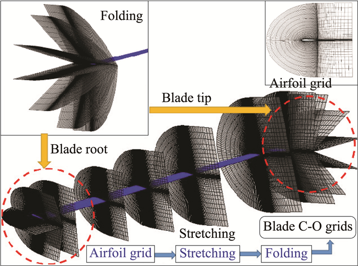
Then, grids around the blade are generated by stretching between the blade typical airfoil sections and folding at the blade tip and root respectively. Finally, grid refinement is quickly fulfilled by solving Poisson equations considering chord length, quarter-chord line and twist distributions of blade, which is showed in Fig. 1, the number of blade grids is 257×75×106. The grids are properly refined within and near the boundary layer while the distance between the first layer of grids and the wall is 5.0×10⁻⁶c (c is the chord length).
|
图 1 桨叶网格 Figure 1 Grids around rotor blade |
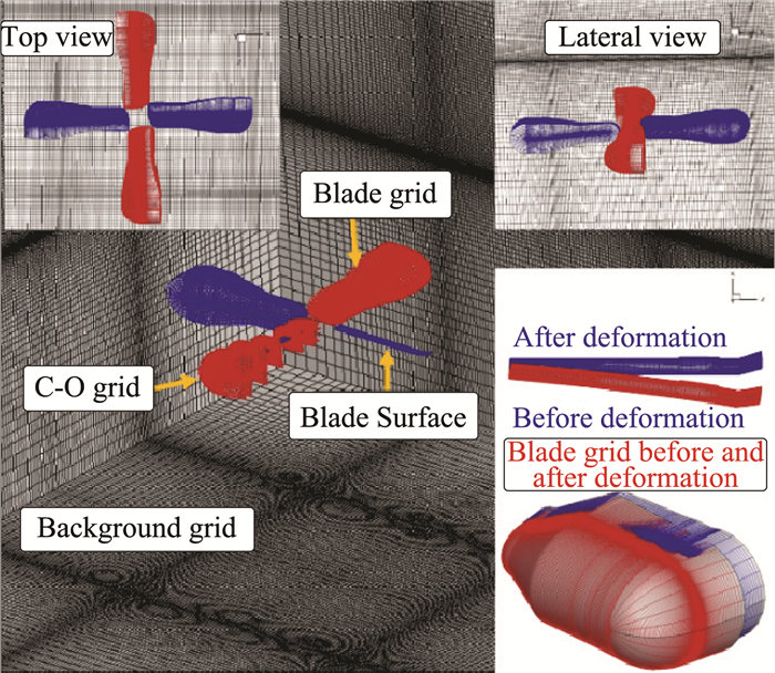
The background grids are Cartesian grids whose number is 190×164×180. Fig. 2 shows the overall schematic of moving-embedded grid system. Considering the elastic blade, the comparison of blade grids before and after the deformation is given in this figure.
|
图 2 运动嵌套网格系统流程图 Figure 2 Overall schematic of a moving-embedded grid system |
The moving-embedded grid generation method is established to adapt the motion characters of blades including flapping, pitching and rotation with elastic deformation. Based upon the characteristics of grid for rotor flowfield calculation, considering the hole-map method, a hole-cutting method[25-26] to solve the relationships between background grids and rotor blade grids is adopted which named "perspective drawing" method. The "perspective drawing" method is divided into the following four steps: the first step is to build an array of blade grids while the background grid size is taken as the resolution ratio, and obtain relevant grid parameters; the second step is to read the wall points in blade grids in a circular manner, update the established array according to the ordinal numbers of the wall points in background grid, and finally obtains the perspective of the blade surface, which indicates the minimum range of the hole; the third step is to read the points of grid outer surface in a circular manner, update the established array according to the ordinal numbers of grid outer surface points in background grid, and finally obtains the perspective of the blade surface, which indicates the maximum range of the hole; the fourth step is to determine the hole point based on the established "perspective drawing".
The donor searching of contributing units is another key technique in the moving-embedded grid method. The donor searching method is basically using the Inverse Map (IM) method. IM is used to find the corresponding contribution units on the curve grids of fixed point. When searching the contribution unit of a point, the method can reduce the number of units to be searched to several or even one. Because the essence of IM method is to judge the unit correspondences among grids, the "perspective drawing" method can be extended to the establishment of Inverse Map.
1.2 CFD/CSD coupling methodIn order to obtain rotor airloads to previously estimate BVI noise sources information, the unsteady, three-dimensional flowfield details are required. And rotor blades are highly flexible, structural deformations have significant influences on rotor aerodynamic characteristics. Therefore, the CFD code and CSD code interact with each other in prediction of rotor aerodynamic characteristics.
The Navier-Stokes governing equations in the conservative form are:
| $ \frac{{\text{d}}}{{{\text{d}}t}}\iiint\limits_V {\mathit{\boldsymbol{Q}}{\text{d}}v} + \iint\limits_S {\mathit{\boldsymbol{F}} \cdot \mathit{\boldsymbol{n}}{\text{d}}s} - \iint\limits_S {{\mathit{\boldsymbol{F}}_v} \cdot \mathit{\boldsymbol{n}}{\text{d}}s} = 0 $ | (2) |
Where
In spatial discretization, the third-order MUSCL interpolation scheme[27] and flux-difference splitting Roe scheme[28] are adopted, the monotone upwind interpolation method is used to calculate the surface around the variable unit:
| $ \begin{array}{l} {U_R} = {U_{i + 1}} - \frac{1}{4}\left[ {\left( {1 + \kappa } \right){\Delta _ - } + \left( {1 - \kappa } \right){\Delta _ + }} \right]{U_{i + 1}}\\ {U_L} = {U_i} + \frac{1}{4}\left[ {\left( {1 + \kappa } \right){\Delta _ + } + \left( {1 - \kappa } \right){\Delta _ - }} \right]{U_i} \end{array} $ | (3) |
Where
The dual-time stepping method is adopted while the implicit LU-SGS scheme is employed to the pseudo-time step. The viscous region of blade is calculated by S-A turbulent model. The inner boundary is no-slip condition for Navier-stokes equations, and the farfield boundary condition is determined by Riemann invariant. To further enhance the computational efficiency, an appropriate parallel strategy is employed. In the calculation of forward flight condition, each case is calculated as a state with 4 rotation cycles and each circle is calculated at every 0.5° azimuth.
The CSD module is developed based on Hamilton's variational principle:
| $ \int_{{t_1}}^{{t_2}} {\left( {\delta U - \delta T - \delta W} \right){\rm{d}}t} = 0 $ | (4) |
Where δU is the variation of strain energy, δT is the variation of kinematic energy, and δW is the virtual work done by external forces which are aerodynamics loads in this case.
To improve the dynamics prediction accuracy of a rotor with complicated blade tips, multiple beam elements are used for blade-tip modeling. The modified tip beam element could be expressed as:
| $ {\left\{ \begin{array}{l} \mathit{\boldsymbol{q}}\\ {\mathit{\boldsymbol{\dot q}}}\\ {\mathit{\boldsymbol{\ddot q}}} \end{array} \right\}^{n - 1}}{\rm{ = }}{\left[ \mathit{\Lambda } \right]^{n - 1}}{\left\{ \begin{array}{l} \mathit{\boldsymbol{q}}\\ {\mathit{\boldsymbol{\dot q}}}\\ {\mathit{\boldsymbol{\ddot q}}} \end{array} \right\}^{n - i}} $ | (5) |
Where
The discrete equations of motion (Equations 6) for each element are assembled to form the motion equations of blade. These equations are then solved by using Newmark-Beta method to obtain the blade structural deflection affected by aerodynamic forces which are calculated by the present CFD solver.
| $ \left[ {{M_i}} \right]\mathit{\boldsymbol{\ddot q}} + \left[ {{C_i}} \right]\mathit{\boldsymbol{\dot q}} + \left[ {{K_i}} \right]\mathit{\boldsymbol{q}} + {\mathit{\boldsymbol{F}}_i} = 0 $ | (6) |
Where [Mi], [Ci], [Ki], Fi are the element mass, damping, stiffness matrix and force vector.
When the CFD method and the CSD method are established respectively, a loose CFD/CSD coupling strategy is developed to transfer information between fluid and structure. When the moving-embedded grid system is generated, after the initial calculation, the CSD module is calculated and the rotor blade deformation is obtained firstly. The CFD blade grids are deformed based upon the blade deformation results by spring simulation method[31-32]. The deformed blade grids are input into the CFD calculation module secondly. Then the CFD calculation results are returned to the CSD module, and the iterative calculation of above steps is implemented until the rotor blades structural deformations and airloads converge.
For trimming of an isolated rotor, three control variables are determined based on specific flight condition. In this paper, the rotor thrust coefficient CT and the first harmonic flapping β1c and β1s are targeted in order to get the similar aeroacoustic characteristics.
1.3 FW-Hpds methodThe aeroacoustic characteristics of rotor can be predicted by the Ffowcs Williams-Hawkings equations with penetrable data surface (FW-Hpds equations) in the time domain, which is valid even if the integration surface is in the nonlinear region.
| $ p'\left( {x,t} \right) = {{p'}_T}\left( {x,t} \right) + {{p'}_L}\left( {x,t} \right) $ | (7) |
| $ \begin{array}{l} 4{\rm{ \mathsf{ π} }}{{p'}_T}\left( {x,t} \right) = \int_f {{{\left[ {\frac{{{\rho _0}\left( {{{\dot U}_n} + {U_{\dot n}}} \right)}}{{r{{\left( {1 - M{a_r}} \right)}^2}}}} \right]}_{{\rm{ret}}}}{\rm{d}}s} + \\ \int_f {{{\left[ {\frac{{{\rho _0}{U_n}\left( {r\dot M{a_r} + {c_0}\left( {M{a_r} - M{a^2}} \right)} \right)}}{{{r^2}{{\left( {1 - M{a_r}} \right)}^3}}}} \right]}_{{\rm{ret}}}}{\rm{d}}s} \end{array} $ | (8) |
| $ \begin{array}{l} 4{\rm{ \mathsf{ π} }}{{p'}_L}\left( {x,t} \right) = \frac{1}{{{c_0}}}\int_f {{{\left[ {\frac{{{{\dot L}_r}}}{{r{{\left( {1 - M{a_r}} \right)}^2}}}} \right]}_{{\rm{ret}}}}{\rm{d}}s} + \\ \;\;\;\;\int_f {{{\left[ {\frac{{{L_r} - {L_i}M{a_i}}}{{r{{\left( {1 - M{a_r}} \right)}^2}}}} \right]}_{{\rm{ret}}}}{\rm{d}}s} + \\ \;\;\;\;\frac{1}{{{c_0}}}\int_f {{{\left[ {\frac{{{L_r}\left( {r\dot M{a_r} + {c_0}\left( {M{a_r} - M{a^2}} \right)} \right)}}{{{r^2}{{\left( {1 - M{a_r}} \right)}^3}}}} \right]}_{{\rm{ret}}}}{\rm{d}}s} \end{array} $ | (9) |
| $ {U_i} = \left[ {1 - \left( {\rho /{\rho _0}} \right)} \right]{v_i} + \left( {\rho {u_i}/{\rho _0}} \right) $ | (10) |
| $ {L_i} = {P_{ij}}{{\hat n}_j} + \rho {u_i}\left( {{u_n} - {v_n}} \right) $ | (11) |
Where p′T is the sound pressure of thickness noise, p′L is the sound pressure of loading noise,
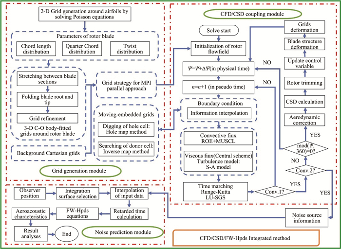
Fig. 3 shows the calculation flow of the present CFD/CSD/FW-Hpds integrated method, which includes the gird generation module, the CFD/CSD coupling module and the noise prediction module.
|
图 3 CFD/CSD/FW-Hpds综合方法流程图 Figure 3 Flow chart of CFD/CSD/FW-Hpds integrated method |
In order to verify the validity of the rotor CFD/CSD coupling method for the aerodynamic performance simulation of the rotor in forward flight, the UH-60A helicopter rotor which has wind tunnel test data and specific structural parameters is selected as a numerical example. The operating conditions are as follow: advance ratio μ=0.368, pitch angle θ(t)=13.55°+3.39°cosψ(t)-9.62°sinψ(t), where ψ(t) stands for azimuthal angle. According to the structural characteristics of the UH-60A blade, 50 finite element units are divided along the spanwise direction.
Fig. 4 shows the comparisons of the predicted and measured blade surface pressure coefficient distributions of the UH-60A rotor in forward flight while the measured blade surface pressure coefficient distributions are from Reference[31], and the rotor CFD/CSD coupling predicted data (considering the elastic deformation) and the rigid rotor CFD predicted data are also compared, while the trimming calculation is considered. In Fig. 4, r/R represents the relative radius of the blade section. As can be seen from the figure, compared to the rigid rotor CFD predicted data, the CFD/CSD coupling predicted data considering the elastic deformation have better agreements with the experimental data at different azimuthal angles, which indicates that the CFD/CSD coupling method developed in this paper can be used to simulate the aerodynamic characteristics of the rotor in forward flight. The CFD/CSD coupling method can provide reliable noise source information for simulating BVI noise characteristics of the rotor effectively.

|
图 4 前飞状态UH-60A旋翼桨叶表面压强分布的计算值与测量值对比 Figure 4 Comparisons of the predicted and measured blade surface pressure coefficient distributions of the UH-60A rotor in forward flight |
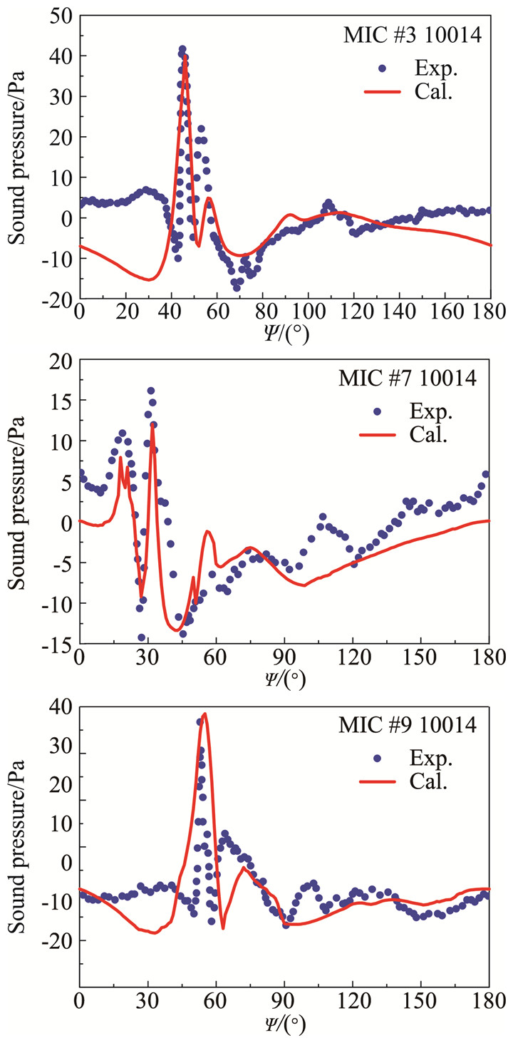
The noise characteristics of rotor under a BVI test condition 10014 state[32]of the AH-1G/OLS model rotor in forward flight have been simulated. The operating conditions are: the blade tip Mach number Matip=0.644, advance ratio μ=0.164, tip-path-plane angle of attack αTPP=1°, lift coefficient CT=0.0054, Reynolds number Re=1.6×10⁶. In this state, the rotor not only has periodic variable pitch motion, but also has periodic flapping motion. The pitch and flapping laws of rotor blades are as follows: pitch angle θ(t)=6.14°+0.9°cosψ(t)-1.39° sinψ(t), flapping angle β(t)=0.5°-1.0°cosψ(t).
In Fig. 5, the comparisons of the calculated results with the available experimental data at three observer positions have been shown, while the positions MIC#3 (0, -27.467c, -15.858c), c is the chord length, MIC #7 (-13.733c, -23.787c, -15.858c) and MIC#9 (13.733c, -23.787c, -15.858c) are in the direction of propagation with large BVI noise. The numerical results agree well with the experimental results. For example, in position MIC#3, the positive peak sound pressure at approximately 45° azimuthal angle is calculated accurately in amplitude and phase, and this is the typical characteristic of the BVI state. It is clearly shown that the method has been proved to be effective to simulate the aerodynamic and aeroacoustic characteristics, especially BVI noise characteristics.
|
图 5 前飞状态AH-1G/OLS模型旋翼声压时间历程的计算值与测量值对比 Figure 5 Comparisons of the predicted and measured time histories of sound pressure of the AH-1G/OLS model rotor in forward flight |
The aeroacoustic characteristics of the UH-60A rotor in oblique descending flight are calculated with IBC control and without IBC control. The operating conditions are: Matip=0.642, μ=0.164, αs=-4°, the simulations presented are trimmed. The descent angle is 10°. The blade pitch angle including IBC input is defined as follows:
| $ \begin{array}{l} \theta = {\theta _0} + {\theta _{1C}}\cos \psi + {\theta _{1S}}\sin \psi + \\ \;\;\;\;\;\sum\limits_{k = 1}^n {{\theta _{IBCk}}\cos \left( {{k_{IBCk}}\psi + {\psi _{IBCk}}} \right)} \end{array} $ | (12) |
Where n is the number of harmonics of different frequencies, θ0 is the collective pitch angle, θ1C is the lateral cyclic pitch angle and θ1S is the longitudinal cyclic pitch angle. If the single frequency harmonic input is used, the formula is simplified as: θ=θ0+θ1Ccosψ+θ1Ssinψ+θIBCcos(kIBCψ+ψIBC), where θIBC is the amplitude input, kIBC is the frequency input, and ψIBC is the phase angle input.
Rotor BVI noise reduction effects of different IBC control inputs such as different phase angles, different amplitudes and different frequencies are given.
2.1 Phase sweepingTable 1 shows the comparisons of CT (thrust coefficient) and CQ (torque coefficient) with and without IBC phase sweeping control while the amplitude is 2° and the frequency order 2/rev. It is evident that the CT and CQ remain stable with IBC control, which proves that the aerodynamic performance of the rotor can be guaranteed while BVI noise is reduced.
| 表 1 CT和CQ的相位扫掠值 Table 1 Comparisons of CT and CQ with phase sweeping |
|
|
The comparisons of noise sound pressure level under polar coordinate with IBC control (amplitude 2°, phase angle 135°, the frequency order 2/rev) and without IBC control are given in Fig. 6. The observer positions are 3.09R away from the disk center and 30° below the rotor disc. Under IBC control, BVI noise of the rotor in this observation plane is obviously reduced (up to 4dB), especially in the region where BVI noise radiation is relatively large in front of the rotor.

|
图 6 有无IBC控制的声压级对比 Figure 6 Comparisons of noise sound pressure level under polar coordinate with and without IBC control |
The wavelet time-scale graphs with and without IBC control are given in Fig. 7 while IBC control parameters are the same as Fig. 6. The abscissa is in one rotation period and the ordinate is the size of the scale. The wavelet analysis method is adopted from Reference[33]. The sixth-order wavelet decomposition is adopted for helicopter rotor noise while the scale a=24. It can be seen that the characters of BVI noise signal is obvious without IBC control, the energy is strong (corresponding to red) and corresponding to the time domain impulse. BVI noise signal and energy is obviously weakened with IBC control.

|
图 7 一个旋转周期内有无IBC控制的小波时间尺度对比图 Figure 7 Comparisons of wavelet time-scale graphs with and without IBC control in one rotation cycle |
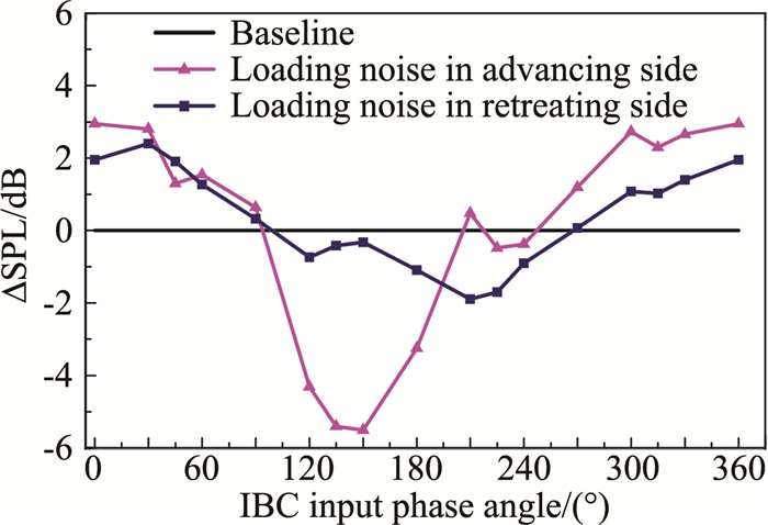
Fig. 8 shows the comparisons of noise SPL of different phase angles.IBC active control amplitude is 2°, the frequency order is 2/rev, and the phase angles are swept from 0° to 360°. As can be seen from Fig. 8, while selecting reasonable phase angles such as from 100° to 200°, BVI noise in the advancing side can be greatly reduced. It is obvious that a significant reduction of the predicted BVI noise level is achieved with a minimum value at the phase of 135° and 150° in the advancing side, where the noise reduction benefit of about 5.5 dB is obtained. At the same time, it can be seen that BVI noise can also be reduced in the retreating side while selecting reasonable phase angles; but if the phase angle is small, BVI noise may become larger, and the noise increment will decrease rapidly with the increase of the phase angle, when the phase angle reaches to 100°, BVI noise begins to decrease and can be reduced by 2 dB.
|
图 8 不同IBC相位角度输入下的噪声声压级对比 Figure 8 Comparisons of noise SPL with different IBC phase angle inputs |
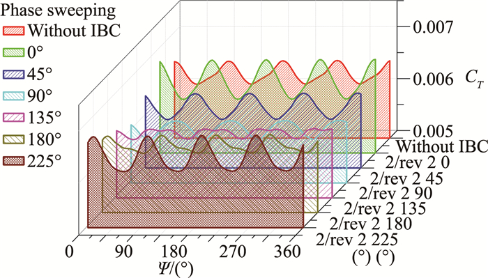
The comparisons of time-variation CT with phase sweeping are given in Fig. 9, which show that the large fluctuations of time-variation CT tend to be stable with IBC phase angle control from 90° to 180° while the noise SPL reduced and the average values remain constant. The periodic load of rotor fluctuates moderately and the vibration decreases while the vibration reduction is one of the main purposes of IBC methodology, which show that BVI noise and the vibration can be decreased simultaneously by reasonable IBC control.
|
图 9 CT的相位扫掠对比 Figure 9 Comparisons of CT with phase sweeping |
On the basis of the analysis of phase sweeping results, the amplitude sweep of BVI noise is investigated.IBC active control frequency order is 2/rev, and the phase is 135°, the amplitudes are swept from 0° to 3°. The amplitude sweeping curve diagram in Fig. 10 shows the effects of different IBC input amplitudes in the advancing side which indicates that the total rotor noise reduction effect is more and more obvious with the increase of IBC input amplitude of the same phase angle in the advancing side. However, when IBC amplitude increases to a larger value, the ability to reduce BVI noise will tend to be eased. When the amplitude reaches to 3°, BVI noise can be reduced by 7 dB.

|
图 10 不同IBC幅值输入下的噪声声压级对比 Figure 10 Comparisons of noise SPL with different IBC amplitude inputs |
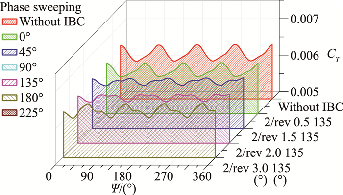
Fig. 11 shows the comparisons of time-variation CT with amplitude sweeping. It is a clear demon-stration that when BVI noise reduced obviously with different amplitude inputs, the average values of time-variation CT remain stable and the fluctuations tend to be gently, which show that the vibration reduction is obtained at the same time of BVI noise reduced by IBC control.
|
图 11 CT的幅值扫掠对比 Figure 11 Comparisons of CT with amplitude sweeping |
Then, Fig. 12 shows the comparisons of the noise reduction effect of different IBC frequency inputs with the same amplitude 2° and the same phase angle 135°, which reveal thatrotor BVI noise can be reduced by different IBC frequency harmonic inputs in the advancing side. The noise reduction effect of 2/rev frequency harmonic input is the best among the single-frequency harmonic inputs, up to 5.5dB. At the same time, it can be seen that noise reduction effects of the multi-frequency harmonic inputs are slightly better than that of the single- frequency harmonic inputs. When 2/rev and 3/rev are used together, BVI noise SPL is reduced by over 7 dB.

|
图 12 不同IBC频率输入下的噪声声压级对比 Figure 12 Comparisons of noise SPL with different IBC frequency inputs |
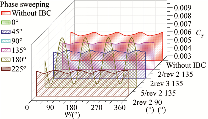
Fig. 13 shows the comparisons of time-variation CT with frequency sweeping. As can be seen from Fig. 12, the best vibration reduction was achieved using 2/rev frequency IBC control, with 6/rev frequency IBC control being the next best for single-frequency harmonic input. The vibration are not increased at other frequencies with the application of the same amplitude 2° and the same phase angle 135° except with 5/rev frequency control, while the noise SPL increases, and at the same time the time-variation CT fluctuations became more violent, which show that BVI noise and the vibration are all increased with 5/rev frequency control, the control parameter needs to be avoided.
|
图 13 CT的频率扫掠对比 Figure 13 Comparisons of CT with frequency sweeping |
It is controversy whether the second-order harmonic or the fourth-order harmonic control is better to reduceBVI noise for a four-bladed rotor[22-23]. In order to solve this question, Fig. 14 shows the rotor noise SPL comparisons of 2/rev and 4/rev with different phase angle controls. The results show that BVI noise reduction effect of second-order harmonic control is better than that of the fourth-order harmonic control for a four-bladed rotor, especially in the retreating side. With 2/rev frequency control, the noise can be reduced in large range of phase angles and BVI noise can be reduced more.

|
图 14 2/rev和4/rev频率输入下的噪声声压级对比 Figure 14 Comparisons of noise SPL with 2/rev and 4/rev frequency inputs |
Based upon the parameter influence investigation of IBC active control, the noise reduction effects with IBC control under different flight conditions such as different flight velocity (different advance ratio) and different flight trajectory (different descent angle) are given.
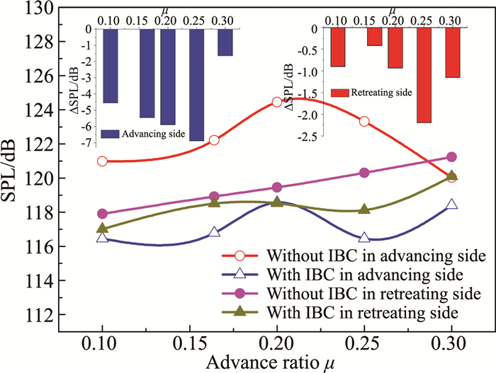
3.1 Different flight velocity (different advance ratio)Fig. 15 shows the comparisons of noise SPL with different flight velocities (advance ratios) with and without IBC control.IBC control parameters are: amplitude 2°, phase angle 135°, frequency order 2/rev, and the descent angle is 10°. As can be seen from the figure, BVI noise increases with the increase of advance ratio without IBC control; when the advance ratio reaches to 0.20, BVI noise arrives at the maximum value; then, when the advance ratio continues to increase, BVI noise gradually decreases. That is because when the advance ratio is further increased, the blade tip vortex generated by the preceding blade is rapidly shed from the rotor disk, which reduces BVI noise SPL. It can be seen that the noise reduction in the advancing side is obvious with IBC control, while the advancing side is the strongest radiation direction of BVI noise. BVI noise SPL can be reduced by 7 dB at the advance ratio of 0.25. However, the noise in the retreating side is not strong while the noise reduction effect is not obvious. As can been seen from the figure, the noise SPL can be reduced by 2.2 dB at the advance ratio of 0.25 in the retreating side.
|
图 15 不同前进比下有无IBC控制的噪声声压级对比 Figure 15 Comparisons of noise SPL with different advance ratios |
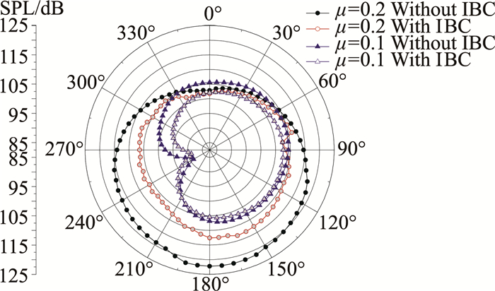
The comparisons of noise SPL under polar coordinate with and without IBC control under different advance ratios are given in Fig. 16. It can be seen that the rotor noise SPL at the advance ratio of 0.2 is significantly greater than that at the advance ratio of 0.1 without IBC control, which indicates that the strong blade-vortex interaction is occurred.When the advance ratio is 0.1, the noise SPL is not strong, which show that BVI noise is not obvious, and the main noise radiation direction is in the advancing side. With the increasing of the advance ratio, the phenomenon of BVI is becoming obvious, and the main noise radiation direction is in front of the rotor, such as in Fig. 6 while the advance ratio is 0.164 and in Fig. 16 while the advance ratio is 0.2. With IBC control, the rotor noise under different advance ratios can all be reduced, especially when the advance ratio is 0.2 while the strong BVI existing. BVI noise can be reduced significantly, such as the positions of the below front of the rotor disc which is the main propagation direction of BVI noise.
|
图 16 不同前进比下有无IBC控制的声压级对比 Figure 16 Comparisons of SPL under polar coordinate with and without IBC control under different advance ratios |
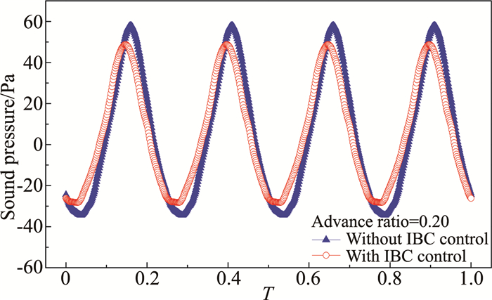
In Fig. 17, the sound pressure time histories of BVI noise with and without IBC are compared at the advance ratio of 0.20. The results show that the positive sound pressure peak and the negative sound pressure peak of IBC control are lower than those without IBC control, andthe slope of sound pressure time history curve is smoother with IBC control than that without IBC control.
|
图 17 有无IBC控制的声压时间历程对比 Figure 17 Comparisons of sound pressure time histories |
In Fig. 18, the noise frequency spectrums of BVI noise with and without IBC is given at the advance ratio of 0.20. With IBC control, the medium-frequency (6-18 times of rotation frequency) noise can be reduced by more than 10 dB, while the medium-frequency noise is the main part of BVI noise, which shows that IBC control can reduce BVI noise effectively.

|
图 18 有无IBC控制的噪声频谱对比 Figure 18 Comparisons of noise frequency spectrums |
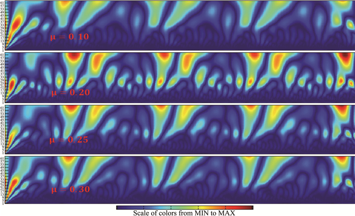
The comparisons of wavelet time-scale graphs without IBC control with different advance ratios are given in Fig. 19 while the scale a=32 while the abscissa is in one rotation period and the ordinate is the size of the scale. It can be seen that the characters of BVI noise signal are obvious without IBC control, especially when the advance ratio is 0.20, where the energy is strong and BVI noise is the strongest.
|
图 19 一个旋转周期内不同前进比下的有无IBC控制的小波时间尺度对比图 Figure 19 Comparisons of wavelet time-scale graphs without IBC control with different advance ratios in one rotation cycle |
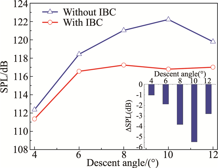
Fig. 20 shows the comparisons of noise SPL with different flight trajectory (different descent angle) with and without IBC control.IBC control parameters are: amplitude 2°, phase angle 135°, frequency order 2/rev, and the advance ratio 0.164. The oblique descent flight condition is one of the most easily conditions to generate helicopter BVI noise. As can be seen from the figure, rotor BVI noise SPL increases with the increase of descent angle without IBC control. When the descent angle reaches to 10°, BVI noise SPL arrives at the maximum value. Then, BVI noise gradually decreases with the descent angle continues to increase. With IBC control, BVI noise can be effectively reduced under different flight trajectory conditions, especially when the descent angle is 10° while BVI noise SPL arrives at the maximum value. As can be seen, IBC control method can effectively reduce BVI noise in the oblique descending flight state.
|
图 20 不同下降角时的噪声声压级对比 Figure 20 Comparisons of noise SPL with different descent angles |
Fig. 21 shows the sound pressure time histories with and without IBC control under different descent angle states. When the descent angle is 10°, the blade-vortex interaction is the most serious, the positive and negative pressure peak decreased obviously with IBC control, andBVI noise is effectively reduced. When the descent angle is 4°, the blade-vortex interaction is not serious originally, the rotor noise SPL value is only about 112.5 dB, thus the positive and negative peak pressure are reduced slightly.

|
图 21 不同下降角时的声压时间历程对比 Figure 21 Comparisons of sound pressure time histories with different descent angles |
Fig. 22 shows the wavelet analysis results of different descent angle states with and without IBC control, the scale a=32 while the abscissa is in one rotation period and the ordinate is the size of the scale. The noise signal and energy at the 10° descent angle are obviously stronger than that of the 4° descent angle. In different descent angle states, the rotor noise hotspots have been weakened with IBC control and rotor BVI noise signal and energy have been effectively attenuated.

|
图 22 一个旋转周期内不同下降角下的有无IBC控制的小波时间尺度对比图 Figure 22 Comparisons of wavelet time-scale graphs with and without IBC control with different descent angles in one rotation cycle |
(1) The present CFD/SCD/FW-Hpds integrated method has been proved to be effective to simulate the unsteady aerodynam ic and acoustic characteristics of rotor in forward flight from the validation calculation.
(2) It can be seen from the calculated results thatrotor BVI noise SPL can be reduced more than 7 dB by selecting reasonable IBC control; BVI noise reduction effect of second-order harmonic control is better than that of the fourth-order harmonic control for a four-bladed rotor and the noise reduction effect by the multi-frequency harmonic IBC control is better than that by the single- frequency harmonic IBC control; the control effects show that BVI noise SPL can be effectively reduced by IBC control method under different flight velocities and different flight trajectories.
(3) Comparisons of CT under different IBC control parameters show that rotor BVI noise and the vibration can be decreased simultaneously by selecting reasonable IBC control and meanwhile the aerodynamic performance of the rotor can be guaranteed.
(4) Comparisons of sound pressure time histories show that the positive and negative sound pressure peaks with IBC control are lower than those without IBC control, and comparisons of noise frequency spectrums of BVI noise with and without IBC control indicates that the medium-frequency noise (the main part of BVI noise) can be reduced by more than 10 dB with IBC control, thus resulting in the reduction of rotor BVI noise SPL.
(5) Comparisons of wavelet time-scale graphs show that the characters of BVI noise signal is obvious without IBC control in oblique descending flight. The rotor noise hotspots can be obviously weakened with IBC control while BVI noise signal and energy can be effectively attenuated.
| [1] |
Megan S M. Helicopter blade-vortex interaction noise with comparisons to CFD calculations[C]//NASA TM-1104231996.
(  0) 0) |
| [2] |
Yung H Y. Rotor blade-vortex interaction noise[J]. Progress in Aerospace Science, 2000, 36: 97-115. DOI:10.1016/S0376-0421(99)00012-3 (  0) 0) |
| [3] |
Sant T, Kuik G V, Bussel G J W V. Estimating the angle of attack from blade pressure measurements on the NREL phase VI rotor using a free wake vortex model:axial conditions[J]. Wind Energy, 2006, 9(6): 549-577. DOI:10.1002/(ISSN)1099-1824 (  0) 0) |
| [4] |
Aoyama T, Yang C, Kondo N, et al. Fundamental CFD analysis on main-rotor/tail-rotor interaction noise of helicopters[J]. Chinese Journal of Laboratory Diagnosis, 2004, 53: 215-220. (  0) 0) |
| [5] |
Wang Y, Xu G H, Zhao Q J. Numerical method for predicting rotor aerodynamic noise based on unstructured-grid CFD technology[J]. Acta Aerodynamica Sinica, 2011, 29(5): 559-566. (  0) 0) |
| [6] |
Boud D D. Initial aerodynamic and acoustic study of an active twist rotor using a loosely coupled CFD/CSD method[C]//35th European Rotorcraft Forum. Hamburg, Germany, 2009.
(  0) 0) |
| [7] |
Farassat F, Succi G P. A review of propeller discrete frequency noise prediction technology with emphasis on two current methods for time domain calculations[J]. Journal of Sound and Vibration, 1980, 71(3): 399-419. DOI:10.1016/0022-460X(80)90422-8 (  0) 0) |
| [8] |
Farassat F, Casper J. Towards an airframe noise prediction methodology: survey of current approaches[C]//AIAA 44th Aerospace Sciences Meeting and Exhibit. Reno, Nevada, 2006. AIAA 2006-0210.
(  0) 0) |
| [9] |
Wang B, Zhao Q J, Xu G H, et al. Numerical analysis on noise of rotor with unconventional blade-tips based on CFD/Kirchhoff method[J]. Chinese Journal of Aeronautics, 2013, 26(3): 572-582. DOI:10.1016/j.cja.2013.04.045 (  0) 0) |
| [10] |
Zhao Q J, Xu G H. A study on aerodynamic and acoustic characteristics of advanced tip-shape rotors[J]. Journal of the American Helicopter Society, 2007, 52(3): 201-213. DOI:10.4050/JAHS.52.201 (  0) 0) |
| [11] |
Shi Y J, Zhao Q J, Xu G H. An analytical study of parametric effects on rotor-vortex interaction noise[J]. Proceedings of the Institution of Mechanical Engineers. Part G:Journal of Aerospace Engineering, 2011, 225(3): 259-268. DOI:10.1243/09544100JAERO869 (  0) 0) |
| [12] |
Hu H, Jr L A J, Baeder J D. Computational simulation and analysis of double-swept blade in BVI noise reduction[J]. Advances in Engineering Software, 2005, 36(2): 67-76. DOI:10.1016/j.advengsoft.2004.08.002 (  0) 0) |
| [13] |
Splettstoesser W R, Schultz K J, Kube R, et al. A higher harmonic control test in the DNW to reduce impulsive BVI noise[J]. Journal of the American Helicopter Society, 1994, 39(4): 3-13. DOI:10.4050/JAHS.39.3 (  0) 0) |
| [14] |
Splettstoesser W R, Kube R, Wagner W, et al. Key results from a higher harmonic control aeroacoustic rotor test (HART) in the german-dutch wind tunnel[J]. Journal of the American Helicopter Society, 1997, 42(1): 58-78. DOI:10.4050/JAHS.42.58 (  0) 0) |
| [15] |
Pengel K, Merjer E, Lehmann G. The higher-harmonic control aeroacoustic rotor test (HART) in the DNW-LLF[R]. ADN 68171-99-M-6269, 2000.
(  0) 0) |
| [16] |
Rendy P C, Mark B T, Roberto C. A high-order, linear time-invariant model for application to higher harmonic control and flight control system interaction[R]. NASA TP-2006-213460, 2006.
(  0) 0) |
| [17] |
Norman T R, Theodore C R, Shinoda P, et al. Full-scale wind tunnel test of a UH-60 individual blade control system for performance improvement and vibration, loads and noise control[C]//Proceedings of the 65th Annual Forum of the American Helicopter Society. Grapevine, TX, 2009.
(  0) 0) |
| [18] |
Niesl G, Swanson S M, Jacklin S A, et al. Effect of individual blade control on noise radiation[C]//AGARD Aeroacoustics Conference. Berlinm, Germany, 1994.
(  0) 0) |
| [19] |
Richter P, Eisbrecher H D, Kloeppel V. Design and first tests of individual blade control actuators[C]//16th European Rotorcraft Forum. Glasgow, UK, 1990.
(  0) 0) |
| [20] |
Swanson S M, Jacklin S A, Blaas A, et al. Individual blade control effects on blade-vortex interaction noise[C]//Proceedings of the 50th Annual Forum of the American Helicopter Society, 1994.
(  0) 0) |
| [21] |
Splettstoesser W R, Schultz K J, Wall B, et al. Helicopter noise reduction by individual blade control (IBC)-selected flight test and simulation results[C]//RTA-AVT Symposium, Braunschweig, Germany, 2000.
(  0) 0) |
| [22] |
Yeo H, Romander E A, Norman T R. Investigation of rotor performance and loads of a UH-60A individual blade control system[C]//Proceedings of the 66th Annual Forum of the American Helicopter Society, 2010.
(  0) 0) |
| [23] |
Stephen A J, Axel H, Gary D S, et al. Full scale wind tunnel test of an individual blade control system for a UH-60 helicopter[C]//Proceedings of the 58th Annual Forum of the American Helicopter Society, 2002.
(  0) 0) |
| [24] |
Feng J B, Lu Y, Xu J F, et al. Research on the effect of open-loop active blade-pitch control on rotor BVI noise alleviation[J]. Acta Aeronautica Sinica, 2014, 35(11): 2901-2909. (  0) 0) |
| [25] |
Aoyama A, Yang C, Saito S. Numerical analysis of active flap for noise reduction using moving overlapped grid method[J]. Journal of the American Helicopter Society, 2005, 52(3): 189-200. (  0) 0) |
| [26] |
Li P, Zhao Q J, Zhu Q X. CFD calculations on the unsteady aerodynamic characteristics of a tilt-rotor in a conversion mode[J]. Chinese Journal of Aeronautics, 2015, 28(6): 1593-1605. DOI:10.1016/j.cja.2015.10.009 (  0) 0) |
| [27] |
Colella P. A direct eulerian MUSCL scheme for gas dynamics[J]. Siam Journal on Scientific & Statistical Computing, 1982, 6(1): 104-117. (  0) 0) |
| [28] |
Roe P L. Approximate riemann solvers, parameter vectors, and difference schemes[J]. Journal of Computational Physics, 1981, 43(2): 357-372. DOI:10.1016/0021-9991(81)90128-5 (  0) 0) |
| [29] |
Degand C, Farhat C. A three-dimensional torsional spring analogy method for unstructured dynamic meshes[J]. Computers and Structures, 2002, 80(3-4): 305-316. DOI:10.1016/S0045-7949(02)00002-0 (  0) 0) |
| [30] |
Acikgoz N, Bottasso C L. A unified approach to the deformation of simplicial and non-simplicial meshes in two and three dimensions with guraanteed validity[J]. Computers and Structures, 2007, 85(11-14): 944-954. DOI:10.1016/j.compstruc.2006.11.009 (  0) 0) |
| [31] |
Potsdam M, Yeo H, Johnson W. Rotor airloads prediction using loose aerodynamic/structural coupling[R]. ADA 523729, 2004.
(  0) 0) |
| [32] |
Yu Y H, Tung C, Gallman J, et al. Aerodynamics and acoustics of rotor blade-vortex interactions[J]. Journal of Aircraft, 1995, 32(5): 970-977. DOI:10.2514/3.46825 (  0) 0) |
| [33] |
Zhang Q, Wang H M, Hu Z W. Wavelet analysis of helicopter noise signals[J]. Acta Acustica, 2001, 26(5): 450-454. (  0) 0) |
 2018, Vol. 36


