2. 中国科学院大学, 北京 100049
2. University of Chinese Academy of Sciences, Beijing 100049, China
太阳磁场是主导太阳活动的主要因素[1],而太阳磁场高分辨图像是分析太阳活动与磁场变化之间关系的基本依据。目前,国内外有不少研究机构致力于太阳磁场高分辨观测的研究。其中,瑞典1 m太阳望远镜(Swedish Solar Telescope, SST)[2],美国大熊湖观测站的新太阳望远镜(New Solar Telescope, NST)[3],德国的GREGOR太阳望远镜[4]都在太阳磁场高分辨成像或者光谱观测方面取得了优秀的成果。在国内,国家天文台怀柔观测站的太阳磁场望远镜[5]以及云南天文台的太阳Stokes光谱望远镜[6-7]在太阳磁场的偏振测量方面做出了重要贡献。云南天文台的1 m太阳望远镜以其口径和台址等优势,有望获得在太阳活动中磁场的小尺度结构信息[8]。
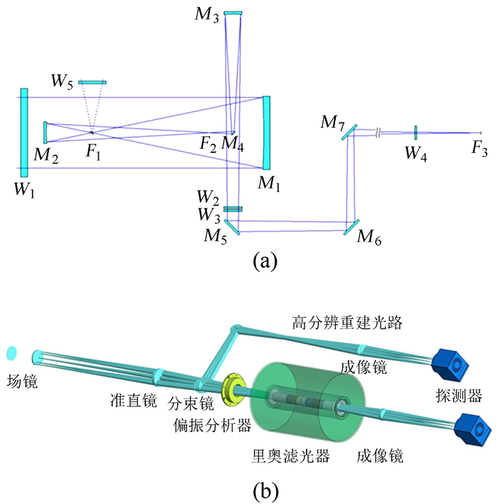
目前,太阳磁场主要通过观测磁敏谱线的偏振分裂获得[9]。然而,太阳望远镜要进行磁场观测,对望远镜及相关仪器的偏振定标必不可少[10-12]。图 1(a)是1 m太阳望远镜的光路示意图,文[10]已经建立相关模型对望远镜进行偏振定标。图 1(b)是1 m太阳望远镜磁场测量终端示意图,该终端安装于图 1(a)中望远镜光路系统的后端,图 1(b)中场镜位于望远镜焦点F3处。由于文[10]中已经对F3前的望远镜系统进行了相应的偏振定标,现在只需要对F3到偏振分析器间的光学器件进行偏振特性的测量,特别是分束镜的偏振效应。

|
| 图 1 (a) 1 m太阳望远镜光路示意图;(b)磁场测量终端 Figure 1 (a) Optical path diagram of NVST; (b) magnetic field measuring equipment |
由于分束镜的偏振效应较弱(一般在百分之几),对偏振特性(本文中用Mueller矩阵表示)的测量更容易受测量系统精度的影响。本文采用空气Mueller矩阵校准法对双旋转波片Mueller矩阵测量系统[13-14]的测量结果进行了校准,提高了系统对Mueller矩阵的测量精度。
1 双旋转波片测量系统及空气Mueller矩阵校准法 1.1 双旋转波片Mueller矩阵测量系统的建立双旋转波片Mueller矩阵测量系统原理如图 2,图中PL1和WP1组成偏振发生器,用于产生已知状态的偏振光,WP2和PL2组成偏振分析器,分析经过样品之后偏振光的状态。图中两个偏振片PL1和PL2的透过轴方向相同且固定不动,测量过程中旋转波片WP1和WP2。Mueller矩阵测量系统从光源到探测器依次是:激光二极管光源,格兰-汤普森棱镜PL1,1/4波片WP1,待测样品,1/4波片WP2,偏振片PL2,滤光片,光功率计。其中,WP1和WP2分别安装在两个电控精密转台上,对波片角度(θ1, θ2)调节。可通过软件控制,实现多组(θ1, θ2)的连续控制及光强的同步采集。测量系统选取θ1,θ2分别调节至(0, 22.5, 45, …, 157.5) 8个位置,一次测量得到64个光强值。其中,θ1,θ2的调节位置是依据Q,U的调制频率及响应矩阵对角化得到的。

|
| 图 2 双旋转波片测量系统原理图 Figure 2 Schematic diagram of dual-rotating-retarder Mueller matrix polarimeter |
系统选取起偏棱镜PL1的起偏方向为Q方向,依次将PL2的透过轴及WP1,WP2的快轴对准至Q方向,并对WP1,WP2的延迟量进行拟合[15-16],得出δ1,δ2分别为87.6°和88.4°。
在建立图 2的测量系统时,选择激光二极管光源,该光源稳定性好,且准直度高,光斑半径小。可以直接使光源发出的光经过偏振发生器、待测样品、偏振分析器和滤光片后直接进入光功率计,而不需要使用透镜,这样既缩短了光路,又避免了透镜的偏振特性对测量结果的影响。
1.2 Mueller矩阵的计算过程测量系统光强与各个光学元件参数关系如下:
| $ I\left( {{\theta _1},{\delta _1},{\theta _2},{\delta _2}} \right) = \left[ {1,0,0,0} \right]{M_{p{l_2}}}{M_{w{p_2}}}\left( {{\theta _2},{\delta _2}} \right){M_s}{M_{w{p_1}}}\left( {{\theta _1},{\delta _1}} \right){M_{p{l_1}}}\left[ {{I_0},0,0,0} \right]. $ | (1) |
定义Si = Mwp1(θ1i, δ1)Mpl1[I0, 0, 0, 0],Si表示与θ1i对应的定标光斯托克斯(Stokes)参量;定义Pj=[1, 0, 0]Mpl2Mwp2(θ2j, δ2),Pj表示与θ2j对应的偏振分析器对光强的调制矩阵。
由1.1所述的测量过程,测得8 × 8光强矩阵:
| $ {I_{8,8}} = {P_{8,4}}{M_s}{S_{4,8}}, $ | (2) |
其中,S4, 8=(S1, …, Si, …, S8);P8, 4=(P1, …, Pj, …, P8)。
通过矩阵运算得出方程的最小二乘解,即
| $ {M_s} = {\left( {{P_{8,4}}{P_{8,4}}} \right)^{ - 1}}{P_{8,4}}{I_{8,8}}{S_{4,8}}{\left( {{S_{4,8}}{S_{4,8}}} \right)^{ - 1}}. $ | (3) |
由于空气是各向同性的,无样品时进行测量根据(3)式计算的Mueller矩阵应该为单位矩阵,而实际测量中相对单位矩阵有偏离。这主要是由于对偏振片和波片参数测量的偏差以及偏振片和波片自身的不理想因素造成的。
本文不具体分析产生上述问题的原因,而是选择采用空气Mueller矩阵校准的方法实现对测量误差的处理和优化。下面分析如何使用空气Mueller矩阵Mc对分束镜这类偏振效应相对较弱的样品进行校准的过程。
空气Mueller矩阵测量的结果Mc可以看作单位矩阵E与一个4 × 4矩阵m0的和,即Mc=E + m0,m0为一个小量。
由于m0≠0是偏振发生器和偏振分析器与理想情形偏离造成的,所以针对空气的测量可以把(2)式展开有
| $ {I_{8,8}} = P_{8,4}^0\left( {E + \Delta p} \right)E\left( {E + \Delta s} \right)S_{4,8}^0, $ | (4) |
其中,(E + Δs)和(E + Δp)分别表示偏振发生器和偏振分析器相对理想情形的偏离程度,Δp,Δs为小量。无样品的测量结果Mc=(E + Δp)(E + Δs)。
当待测样品的Mueller矩阵接近单位矩阵E,即该样品为一个弱偏振原件时,样品实际Mueller矩阵Ms0=(E + Δx),Δx为一个小量。对待测样品直接用(3)式计算出的结果Ms与Ms0的关系如下:
| $ \begin{array}{l} {M_s} = \left( {E + \Delta p} \right)M_{\rm{s}}^0\left( {E + \Delta s} \right)\\ \;\;\;\;\; = \left( {E + \Delta p} \right)\left( {E + \Delta x} \right)\left( {E + \Delta s} \right)\\ \;\;\;\;\; = \left[ {\left( {E + \Delta x} \right)\left( {E + \Delta p} \right) - \left( {\Delta x\Delta p - \Delta p\Delta x} \right)} \right]\left( {E + \Delta s} \right)\\ \;\;\;\;\; = M_{\rm{s}}^0{M_{\rm{c}}} - \left( {\Delta x\Delta p - \Delta p\Delta x} \right)\left( {E + \Delta s} \right)\\ \;\;\;\;\; \approx M_{\rm{s}}^0{M_{\rm{c}}} \end{array} $ | (5) |
| $ M_{\rm{s}}^0 \approx {M_{\rm{s}}}M_{\rm{c}}^{ - 1}. $ | (6) |
Ms0即为使用空气Mueller矩阵Mc进行校准后的结果,该式近似精度与Δp,Δx趋近无穷小的程度有关。
使用空气Mueller矩阵进行校准后,实验测量系统的误差主要来源于公式的近似误差以及光强不稳定性。
2 分束镜Mueller矩阵的测量先用调试好的测量系统进行空气Mueller矩阵的测量,并将测量结果Mc用于后续测量的校准;接着对一块标准的K9玻璃进行入射角从0°到50°的Mueller矩阵测量,比较测量结果和理论值的差别;然后用测量系统对待测分束镜样品进行测量;最后对测量系统的误差进行分析。
2.1 无样品时的空气Mueller矩阵按照1.2节的介绍,将测得的光强矩阵I8, 8、波片的延迟量87.6°和88.4°及方位角(0, 22.5, …, 157.5)代入(3)式得出空气的Mueller矩阵:
| $ {M_{\rm{c}}} = \left[ {\begin{array}{*{20}{c}} 1&{ - 0.003\;4}&{0.017\;5}&{0.000\;9}\\ { - 0.001\;8}&{1.004\;3}&{ - 0.003\;9}&{ - 0.002\;9}\\ { - 0.019\;6}&{0.000\;9}&{1.005\;0}&{ - 0.000\;5}\\ {0.000\;7}&{0.003\;5}&{0.000\;7}&{1.000\;8} \end{array}} \right], $ |
测得的空气Mueller矩阵并不是一个具有实际物理意义的矩阵,而是测量系统不完美程度的表征。该矩阵反映了不进行校准的测量误差在2%左右,极大地限制了对样品测量的精度。
在后续测量中使用空气矩阵的测量结果Mc对样品Mueller矩阵的测量结果进行校准,以提高测量精度。
2.2 测量平板玻璃Mueller矩阵随入射角变化的结果测量K9平板玻璃在入射角从0°到50°变化时的Mueller矩阵,并比较测量结果与菲涅尔公式得出结果的差别,这样可以从实际测量角度得出Mueller矩阵测量系统的准确度。
设平板玻璃的偏振光P分量和S分量的透过强度比为t,K9玻璃透射光的Mueller矩阵为
| $ M\left( {n,\alpha } \right) = \left[ {\begin{array}{*{20}{c}} 1&{\frac{{1 - t}}{{1 + t}}}&0&0\\ {\frac{{1 - t}}{{1 + t}}}&1&0&0\\ 0&0&{\frac{{2\sqrt t }}{{1 + t}}}&0\\ 0&0&0&{\frac{{2\sqrt t }}{{1 + t}}} \end{array}} \right], $ | (7) |
其中,P,S透过强度比t为折射率n和入射角α的函数。
图 3为K9平板玻璃入射角α从0°到50°变化时的Mueller矩阵,该4 × 4图与(7)式中4 × 4的Mueller矩阵的各个阵元对应。从图 3可以看出,(7)式中的0、1阵元的测量结果与理论值之间的偏差基本在5 × 10⁻³以内。

|
| 图 3 K9平板玻璃Mueller矩阵随入射角变化 Figure 3 Measured Mueller matrix of K9 glass vary with the incident angle |
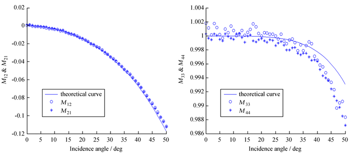
图 4比较了阵元M12,M21,M33,M44的测量值与理论值,可以看出(7)式中非0、1阵元的最大误差也在5 × 10⁻³内。

|
| 图 4 K9玻璃Mueller矩阵阵元M12,M21,M33,M44的测量值与理论值的比较 Figure 4 Compare the measured value of Mueller matrix M12, M21, M33, M44 with the theoretical value |
本节对标准样品K9玻璃的Mueller矩阵测量结果与理论值的比较,可得使用空气Mueller矩阵校准后的误差小于5 × 10⁻³。
2.3 对分束镜样品Mueller矩阵的测量对两块用于1 m太阳望远镜磁场测量的分束镜进行Mueller矩阵测量。一方面可以用准确测量的分束镜Mueller矩阵处理1 m太阳望远镜偏振测量的结果,剔除分束镜的偏振效应造成的起偏和串扰;另一方面,通过比较不同设计下的分束镜的偏振特性,选择起偏和串扰相对较小的方案,以避免起偏和串扰过大对斯托克斯参量Q,U,V信噪比的减弱。
由于分束镜样品都进行镀膜,其Mueller矩阵有参数P,S透过比为t,P,S相位延迟差为δ,分束镜透射光的Mueller矩阵为
| $ M\left( {t,\delta } \right) = \left[ {\begin{array}{*{20}{c}} 1&{\frac{{1 - t}}{{1 + t}}}&0&0\\ {\frac{{1 - t}}{{1 + t}}}&1&0&0\\ 0&0&{\frac{{2\sqrt t }}{{1 + t}}\cos \delta }&{\frac{{2\sqrt t }}{{1 + t}}\sin \delta }\\ 0&0&{ - \frac{{2\sqrt t }}{{1 + t}}\sin \delta }&{\frac{{2\sqrt t }}{{1 + t}}\cos \delta } \end{array}} \right], $ | (8) |
其中,S方向与斯托克斯参量的Q方向平行。
当分束镜的S方向与测试系统定义的Q方向存在θ夹角时,分束镜Mueller矩阵为
| $ \begin{array}{l} M\left( {t,\delta ,\theta } \right) = {m_{\rm{r}}}\left( { - \theta } \right)M\left( {t,\delta } \right){m_{\rm{r}}}\left( \theta \right)\\ \;\;\;\;\;\;\;\;\;\;\;\;\;\; = \left[ {\begin{array}{*{20}{c}} 1&{B\cos 2\theta }&{B\sin 2\theta }&0\\ {B\cos 2\theta }&{{{\cos }^2}2\theta + C{{\sin }^2}2\theta }&{\frac{{1 - C}}{2}\sin 4\theta }&{ - D\sin 2\theta }\\ {B\sin 2\theta }&{\frac{{1 - C}}{2}\sin 4\theta }&{{{\sin }^2}2\theta + C{{\cos }^2}2\theta }&{D\cos 2\theta }\\ 0&{D\sin 2\theta }&{ - D\cos 2\theta }&C \end{array}} \right], \end{array} $ | (9) |
其中,
下面是对1 m太阳望远镜的一块1:9的分束镜A进行Mueller矩阵测量的结果。
| $ {M_{\rm{A}}} = \left[ {\begin{array}{*{20}{c}} 1&{ - 0.072\;9}&{0.001\;2}&{0.001\;7}\\ { - 0.072\;0}&{1.003\;8}&{0.003\;3}&{ - 0.002\;7}\\ {0.003\;7}&{ - 0.003\;4}&{0.989\;8}&{ - 0.127\;2}\\ { - 0.002\;0}&{0.002\;1}&{0.127\;8}&{0.988\;6} \end{array}} \right] $ |
对应的P,S透过比t=1.156;P,S相位延迟差δ=-7.35°;S方向与测试系统Q轴的夹角θ=-0.64°。
经过进一步偏振优化设计后的分束镜B的Mueller矩阵
| $ {M_{\rm{B}}} = \left[ {\begin{array}{*{20}{c}} 1&{0.001\;5}&{ - 0.005\;8}&{ - 0.000\;9}\\ {0.001\;8}&{0.999\;3}&{0.008\;1}&{0.015\;1}\\ { - 0.003\;5}&{ - 0.010\;2}&{0.990\;4}&{0.132\;5}\\ {0.001\;2}&{ - 0.011\;4}&{ - 0.132\;9}&{0.991\;5} \end{array}} \right] $ |
对应的P,S透过比t=1.004;P,S相位延迟差δ=-7.67°;S方向与测试系统Q轴的夹角θ=2.87°。
由于太阳偏振信号Q,U,V相对光强I比较弱,所以在对太阳进行偏振测量时首先要尽量避免仪器的起偏效应(I→Q,U,V),其次避免仪器造成的Q,U,V之间的串扰。比较分束镜A和B的Mueller矩阵测量结果,可以发现经过偏振优化后的分束镜对起偏效应有了很好抑制,将I对Q,U的起偏由原先的7%左右降到0.5%以下。
2.4 测量系统的系统误差和随机误差本文对误差的处理方式如1.3节中所述,分析用空气矩阵Mc进行校准后的误差。用(5)式求解近似的误差如下:
| $ \begin{array}{l} \Delta {M_{\rm{s}}} = \left( {\Delta x\Delta p - \Delta p\Delta x} \right)\left( {E + \Delta s} \right)M_{\rm{c}}^{ - 1}\\ \;\;\;\;\;\;\; = \left( {\Delta x\Delta p - \Delta p\Delta x} \right){\left( {E + \Delta p} \right)^{ - 1}}, \end{array} $ | (10) |
其中,Δx为测量样品的偏振程度,样品偏振特性越弱,Δx越接近0;Δp为偏振分析器相对理想情形的偏差,偏差越小,Δp越接近0。
由2.1节Mc的测量结果可知,当Δs=0时,Δp取最大值为
| $ \Delta {p_{\max }} = \left[ {\begin{array}{*{20}{c}} 0&{ - 0.003\;4}&{0.017\;5}&{0.000\;9}\\ { - 0.001\;8}&{0.004\;3}&{ - 0.003\;9}&{ - 0.002\;9}\\ { - 0.019\;6}&{0.000\;9}&{0.005\;0}&{ - 0.000\;5}\\ {0.000\;7}&{0.003\;5}&{0.000\;7}&{0.000\;8} \end{array}} \right], $ |
结合2.2和2.3中测量样品Δx的最大值可以得出:
| $ \Delta {M_{\rm{s}}} < \left( {\Delta {x_{\max }}\Delta {p_{\max }} - \Delta {p_{\max }}\Delta {x_{\max }}} \right){\left( {E + \Delta {p_{\max }}} \right)^{ - 1}}. $ |
上式近似的最大误差:
| $ \left[ {\begin{array}{*{20}{c}} { - 0.000\;3}&{ - 0.000\;4}&{0.000\;7}&{0.000\;3}\\ {0.000\;4}&{0.000\;2}&{ - 0.002\;0}&{ - 0.000\;1}\\ {0.000\;3}&{ - 0.002\;2}&{0.000\;1}&0\\ {0.000\;4}&0&0&0 \end{array}} \right]. $ |
即针对2.2和2.3中的测量样品,使用(5)式求解的近似误差ΔMs<2 × 10⁻³。
测量系统测得的Mueller矩阵的随机误差可由光强的随机误差得到,图 5为实验前对光强进行稳定性测量的结果,光强的均方根值为5 × 10⁻⁴,且光强稳定后,强度随时间变化小于3 × 10⁻⁴ /min。在一个测量周期(2 min)内,光强的随机误差

|
| 图 5 光强随时间的稳定性(a)和光强的随机起伏(b) Figure 5 The stability of light intensity over time (a) and random fluctuation of light intensity (b) |
由(3)式可得,测得Mueller的第(i, j)个阵元可表示为
| $ M\left( {i,j} \right) = {k_{11}}\left( {i,j} \right){I_{11}} + {k_{12}}\left( {i,j} \right){I_{12}} + \cdots + {k_{88}}\left( {i,j} \right){I_{88}}, $ | (11) |
其中,i, j=1, 2, 3, 4;k11(i, j), k12(i, j), …, k88(i, j)根据P8, 4和S4, 8计算得到;I11, I12, …, I88为光强矩阵I8, 8的各个阵元。
根据随机误差传递公式可得
| $ \delta M{\left( {i,j} \right)^2} = {\left[ {{k_{11}}\left( {i,j} \right)\delta {I_{11}}} \right]^2} + {\left[ {{k_{12}}\left( {i,j} \right)\delta {I_{12}}} \right]^2} + \cdots + {\left[ {{k_{88}}\left( {i,j} \right)\delta {I_{88}}} \right]^2}, $ | (12) |
其中,δI11, δI12, …, δI88为光强矩阵I8, 8的随机误差。
由(12)式及I8, 8,
| $ \delta M = \left[ {\begin{array}{*{20}{c}} {0.0005}&{0.0003}&{0.0003}&{0.0006}\\ {0.0003}&{0.0002}&{0.0002}&{0.0004}\\ {0.0003}&{0.0002}&{0.0002}&{0.0004}\\ {0.0006}&{0.0004}&{0.0004}&{0.0008} \end{array}} \right]. $ |
实验中对空气Mueller矩阵MC进行20组测量的标准差为
| $ {M_{{\rm{std}}}} = \left[ {\begin{array}{*{20}{c}} 0&{0.0002}&{0.0002}&{0.0002}\\ {0.0001}&{0.0002}&{0.0003}&{0.0007}\\ {0.0003}&{0.0005}&{0.0006}&{0.0004}\\ {0.0002}&{0.0003}&{0.0003}&{0.0001} \end{array}} \right]. $ |
由误差传递计算的结果及实验测得结果可得,随机误差对Mueller矩阵测量结果的影响小于10-3。
Mueller矩阵系统使用空气矩阵Mc校准后,系统误差ΔM<2 × 10⁻³,随机误差δM<10-3。在2.2节中,对K9平板玻璃的测量值与理论值的偏差在5 × 10⁻³以内。综合考虑,本套测量系统用于文中样品的测量误差小于5 × 10⁻³。
由于空气Mueller矩阵校准法用(5)式中的近似,因此,仅适用于对弱偏振器件的Mueller矩阵测量,对起偏和延迟效应小于10%的样品的测量能达到5 × 10⁻³以内的测量精度。
3 总结本文以测量1 m太阳望远镜分束镜的Mueller矩阵为出发点,使用空气Mueller矩阵校准法对Mueller矩阵测量结果进行校准,将Mueller矩阵测量精度由2%提高到5 × 10⁻³。比较了标准样品K9平板玻璃的Mueller矩阵测量结果与理论值间的差别,并运用该测量系统对1 m太阳望远镜偏振测量中的分束镜进行了准确测量,比较了经过偏振优化的分束镜与未经过偏振优化的分束镜之间的差别和影响,这对1 m太阳望远镜的偏振测量以及分束镜方案的优化是必不可少的。
使用空气Mueller矩阵校准法后,Mueller矩阵测量系统的测量精度初步满足对弱偏振器件的偏振特性的测量。如果需要进行更高精度的测量和定标,则需要在测量系统中使用更标准的偏振片和波片,并且提高光源的稳定性。
| [1] |
刘煜, 张洪起, 包曙东. 太阳磁场观测研究[J]. 天文学进展, 2001, 19(1): 34–44 Liu Yu, Zhang Hongqi, Bao Shudong. A research on observation of solar magnetic field[J]. Progress in Astronomy, 2001, 19(1): 34–44. |
| [2] | Van Noort M J, Rouppe van der Voort L H M. Stokes imaging polarimetry using image restoration at the Swedish 1-m Solar Telescope[J]. Astronomy & Astrophysics, 2008, 489(1): 429–440. |
| [3] | Cao Wenda, Jing Ju, Ma Jun, et al. Diffraction-limited polarimetry from the Infrared Imaging Magnetograph at Big Bear Solar Observatory[J]. Publications of the Astronomical Society of the Pacific, 2006, 118(844): 838–844. |
| [4] | Lagg A, Solanki S K, Doerr H P, et al. Probing deep photospheric layers of the quiet Sun with high magnetic sensitivity[J]. Astronomy & Astrophysics, 2016, 596: 1–13. |
| [5] | Bai X Y, Deng Y Y, Teng F, et al. Improved magnetogram calibration of Solar Magnetic Field Telescope and its comparison with the Helioseismic and Magnetic Imager[J]. Monthly Notices of the Royal Astronomical Society, 2014, 445(1): 49–55. DOI: 10.1093/mnras/stu1711 |
| [6] | Qu Z Q, Zhang X Y, Chen X K, et al. A solar Stokes spectrum telescope[J]. Solar Physics, 2001, 201(2): 241–251. DOI: 10.1023/A:1017978822648 |
| [7] |
梁红飞, 苏同卫, 赵海娟. 太阳Stokes光谱望远镜的结构及其数据处理方法[J]. 天文研究与技术——国家天文台台刊, 2007, 4(3): 249–257 Liang Hongfei, Su Tongwei, Zhao Haijuan. Structure and data processing of the solar Stokes spectral telescope[J]. Astronomical Research & Technology——Publications of National Astronomical Observatories of China, 2007, 4(3): 249–257. |
| [8] | Liu Zhong, Xun Jun, Gu Bozhong, et al. New vacuum solar telescope and observations with high resolution[J]. Research in Astronomy and Astrophysics, 2014, 14(6): 705–718. DOI: 10.1088/1674-4527/14/6/009 |
| [9] | LandiDegl'Innocenti E. Generation and transfer of polarized radiation in the solar atmosphere: physical mechanisms and magnetic-field diagnostic[C]//NASA Conference Publication. 1985: 279-299. |
| [10] | Yuan S. Polarization model for the New Vacuum Solar Telescope[C]//ASP Conference Series. 2014. |
| [11] | Skumanich A, Lites B W, Martínez P V, et al. The calibration of the Advanced Stokes Polarimeter[J]. The Astrophysical Journal Supplement, 2009, 110(2): 357–380. |
| [12] | Beck C, Schlichenmaier R, Collados M, et al. A polarization model for the German Vacuum Tower Telescope from in situ and laboratory measurements[J]. Astronomy & Astrophysics, 2005, 443(3): 1047–1053. |
| [13] | Smith M H. Optimizing a dual-rotating-retarder Mueller matrix polarimeter[C]//International Symposium on Optical Science and Technology. 2002. |
| [14] | Ichimoto K, Shinoda K, Yamamoto T, et al. Photopolarimetric measurement system of Mueller matrix with dual rotating waveplates[J]. Publications of the National Astronomical Observatory of Japan, 2006, 9(1-2): 11–19. |
| [15] |
侯俊峰, 王东光, 邓元勇, 等. 基于最小二乘拟合的波片相位延迟测量[J]. 光学学报, 2011, 31(8): 104–109 Hou Junfeng, Wang Dongguang, Deng Yuanyong, et al. Phase retardation measurement with least square fitting method[J]. Acta Optica Sinica, 2011, 31(8): 104–109. |
| [16] | 侯俊峰. 偏振分析器的高精度偏振定标方法研究及其应用[D]. 北京: 中国科学院大学, 2013. http://www.wanfangdata.com.cn/details/detail.do?_type=degree&id=Y2381327 |


