扩展功能
文章信息
- 朱镇, 孙琪, 杨军星, 杨楠, 宋立杰, 王瑶, 赵楚翘, 刘志辉
- ZHU Zhen, SUN Qi, YANG Junxing, YANG Nan, SONG Lijie, WANG Yao, ZHAO Chuqiao, LIU Zhihui
- 不同材料固定局部义齿患者行头颈部MRI检查的成像效果和安全性比较
- Comparisons of effect and safety of MRI of head and neck in patients with fixed partial dentures made by different materials
- 吉林大学学报(医学版), 2017, 43(06): 1220-1225
- Journal of Jilin University (Medicine Edition), 2017, 43(06): 1220-1225
- 10.13481/j.1671-587x.20170628
-
文章历史
- 收稿日期: 2017-09-13
2. 江苏省镇江市口腔医院修复科, 江苏 镇江 212000
2. Department of Prosthodontics, Zhenjiang Stomatology Hospital, Jiangsu Province, Zhenjiang 212000, China
磁共振成像(magnetic resonance imaging, MRI)技术自20世纪70年代问世以来已获得飞速发展,在全球范围内应用广泛。与其他影像学检查手段比较,MRI能更有效地分辨软组织,通过多序列成像取得组织之间的不同信号,获得更丰富的影像信息,对人体组织无电离辐射影响,且无造影剂的侵入,所以更安全[1]。因而,MRI已成为临床广泛应用和不可或缺的诊断技术。固定局部义齿是治疗小范围牙列缺损的重要修复方式,一般选用各种金属或非金属材料作为其内冠材料。在种植义齿广泛应用于临床之前,固定局部义齿曾是小范围牙列缺损治疗的首选方式,其对于一些因各种原因未能接受种植治疗的患者仍然有重要的临床应用价值。佩戴假牙者行MRI检查普遍受到限制,因为假牙对检查结果有不利影响。国内外有关固定局部义齿对头颈部MRI影响的研究较少,且主要集中于动物实验或临床随机调查[2-4],对不同材料在同一实验条件下的系统性临床研究国内外尚未见报道。本文作者选择3种临床常用的金属和非金属共内冠材料制作固定局部义齿,并于患者口内行MRI检查,对成像结果进行比较,分析有可能影响伪影大小的因素,以期为临床工作中冠材料的选择提供理论依据。
1 资料与方法 1.1 病例收集在2015年吉林大学口腔医院修复科就诊的牙列缺损患者中,选择适合固定局部义齿修复且志愿参与实验的患者1例。患者知情同意。对患者进行规范牙体预备,取模制作不同材料内冠的固定局部义齿,采用临时粘接剂粘固于基牙。
1.2 纳入标准① 下颌后牙缺失,不愿或无法进行种植义齿修复者;②全身和口腔条件符合固定局部义齿适应证者;③口腔中无其他口腔治疗材料;④体内无任何有可能影响MRI检查的装置者;⑤身体健康,无不适合接受MRI检查的疾病,志愿参与实验。不完全符合上述纳入标准者予以排除。
1.3 材料和仪器钴铬合金(德国BEGO公司),金铂合金(德国贺利氏古莎公司),二氧化锆(美国LAVA公司);临时粘结剂(Tempocem NE, 德国DMG公司);SIEMENS 1.5T MAGNETOM Avanto(德国西门子公司)。
1.4 修复过程① 局麻下对基牙45和47进行固定局部义齿常规牙体预备,制取硅橡胶印模,灌制超硬石膏模型,送加工厂(深圳洋紫荆义齿加工中心)进行固定局部义齿加工,对基牙进行临时冠保护;②各组义齿完成后,口内试戴,调整。采用临时粘结剂就位于基牙,待进行MRI扫描。
1.5 MRI扫描采用SIEMENS 1.5T MAGNETOM Avanto磁共振设备(下文简称为Avanto)分别在矢状面、冠状面和轴面3个方向行T1-TSE和T2-TSE序列扫描。扫描参数见表 1。
| Group | Repetition time(t/ms) | Echo time(t/ms) | FOV(l/mm) | Slice thickness (l/mm) | Flip angle (θ/°) |
Matrix size | Voil size (l/mm) |
Coil |
| T1-TSE | 750 | 11 | 220 | 5 | 90° | 320×320 | 0.9×0.7×5.0 | 8 channel |
| T2-TSE | 5000 | 93 | 0.7×0.7×5.0 | head coil |
将不同材料内冠固定局部义齿分为3组,采用临时粘结剂依次就位于志愿者口内,分别进行扫描。以不戴修复体扫描图像作为对照组。
1.7 MRI图像观察① 采用Codonics ClarityTM Viewer软件,观察伪影的形状和图像信号的变化,目测加以描述;②观测比较伪影大小。通过目测观察并记录图像受伪影干扰的层数,观察并记录各组图像中伪影累及的解剖结构,累及记为“+”,轻微累及或仅累及边缘记为“±”,未累及则不做标记。对矢状位各层面的伪影进行上下方向直径的测量,找出上下直径最大的层面。对冠状位各层面的伪影进行左右方向直径的测量,找出左右直径最大的层面。对轴位各层面进行前后方向直径的测量,找出前后直径最大的层面。并在这3个层面上行进一步观测,在矢状位最大上下直径伪影层面辨认出其轮廓,获得轮廓像素值。与对照图像中同一位置像素进行比较,差别大于30%即判定为伪影[5]。通过该方法确定上下最大直径伪影的轮廓。重复上述步骤测量3次。冠状位和轴位最大直径伪影采取同样方法进行测量。
1.8 固定局部义齿的安全性检测根据患者主观感觉,如有无移位趋势、局部温度升高和牙髓症状等直观判断MRI检查中佩戴固定局部义齿的安全性。
1.9 统计学分析采用SPSS 19.0对数据进行统计学分析。各总体符合正态分布且方差相同。矢状位、冠状位和轴位条件下3种内冠材料伪影的最大直径比较采用t检验。以P<0.05为差异有统计学意义。
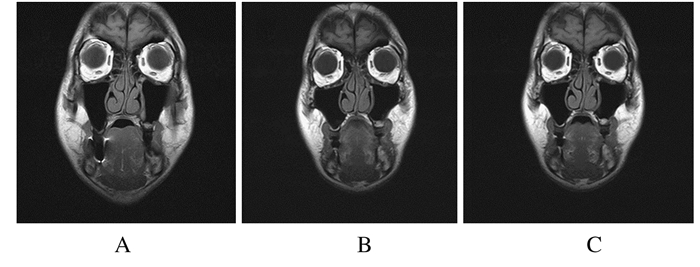
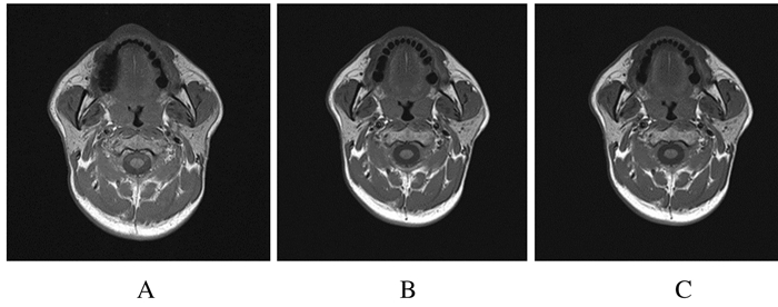
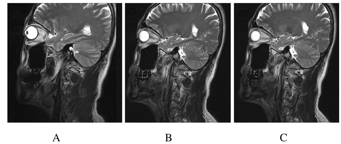
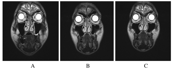
2 结果 2.1 3组不同材料义齿伪影形状和信号表现修复体产生的伪影主要表现为信号的强弱变化以及形状的变化。伪影范围在所累及的中心层面最大,在矢状位、冠状位、轴位图像上有不同表现形式。在矢状位和冠状位图像上,首、末层伪影均表现为小范围的信号增强区域,最大伪影中心信号均部分丢失。矢状面图像最大伪影表现为前后方向直径大于上下方向直径的椭圆形,上下轮廓比前后轮廓清晰;较小伪影形状近似固定桥矢状切面。冠状位图像上,最大伪影表现为倒置圆三角形,左右轮廓比上下轮廓清晰。轴位图像上,各层面伪影均表现为前后径大于左右径的椭圆形信号丢失区域,其内可包含1圈椭圆形高信号带。
2.2 3组不同材料义齿伪影累及层数3组不同材料义齿在冠状位、矢状位和轴位图像上的伪影累及层数检测结果显示:钴铬合金组义齿伪影累及层数明显多于金铂合金组和二氧化锆组。见表 2。
| Material | Coronal | Sagittal | Transverse | |||||
| T1-TSE | T2-TSE | T1-TSE | T2-TSE | T1-TSE | T2-TSE | |||
| Co-Cr alloy | 6 | 6 | 5 | 5 | 3 | 4 | ||
| Au-Pt alloy | 3 | 3 | 3 | 2 | 2 | 1 | ||
| Zirconia | 4 | 3 | 3 | 3 | 2 | 3 | ||
所有伪影仅局限于邻近组织,未累及颅脑和颈部,且未影响颌面部重要组织结构如下颌升支、上颌骨和眼球等(临床工作中,MRI结果通常经综合比对T1和T22种加权图像而得到,因此本研究不讨论T1和T2加权的区别)。3种内冠材料的伪影累及部位见表 3。
| Material | Tooth and periodontium | Mandibular body | Inferior alveolar nerve canal | Maxillary crown | Lingualis | Sublingual gland | Alveololabialis | Musculus depressor anguli oris |
| Co-Cr alloy | + | + | ± | + | + | ± | + | ± |
| Au-Pt alloy | ± | - | - | ± | ± | - | - | - |
| Zirconia | ± | - | - | ± | ± | - | - | - |
| +:Involvement,±:Slight involvement or involvement of margins only.“-”:Without involvement. | ||||||||
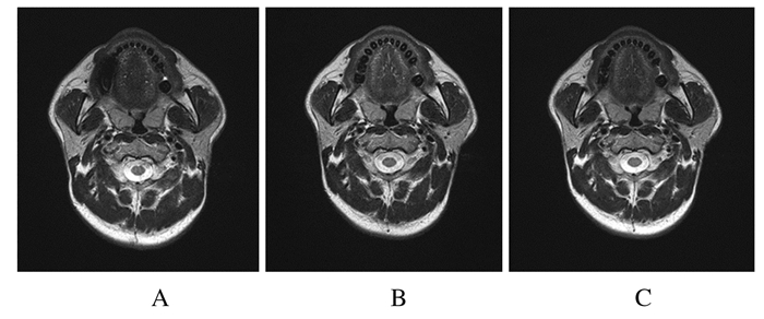
不同材料在矢状位、冠状位和轴位伪影的最大直径比较差异有统计学意义(P<0.05)。钴铬合金组义齿产生的伪影最大直径大于金铂合金组和二氧化锆组(P<0.05)。不同材料义齿在矢状面的T1-TSE和T2-TSE:钴铬合金组>二氧化锆组>金铂合金组。不同材料义齿在冠状面的T1-TSE和T2-TSE:钴铬合金组>二氧化锆组>金铂合金组。不同材料义齿在轴面的T1-TSE和T2-TSE:钴铬合金组>二氧化锆组>金铂合金组。见图 1~7。

|
| 图 1 3种材料在冠状位(A)、矢状位(B)和轴位(C)图像中伪影的最大直径 Figure 1 Maximum diameters of artifacts of three materials in coronal(A), sagittal(B) and axial(C) images |
|
|

|
| A: Co-Cr alloy; B:Au-Pt alloy; C:Zirconia. 图 2 T1-TSE矢状位图像的伪影最大直径 Figure 2 Maximum diameters of artifacts of T1-TSE in sagittal images |
|
|
|
| A: Co-Cr alloy; B:Au-Pt alloy; C:Zirconia. 图 3 T1-TSE冠状位图像的伪影最大直径 Figure 3 Maximum diameters of artifacts of T1-TSE in coronal images |
|
|
|
| A: Co-Cr alloy; B:Au-Pt alloy; C:Zirconia. 图 4 T1-TSE轴位图像的伪影最大直径 Figure 4 Maximum diameters ofartifacts of T1-TSE in axial images |
|
|
|
| A: Co-Cr alloy; B:Au-Pt alloy; C:Zirconia. 图 5 T2-TSE矢状位图像的伪影最大直径 Figure 5 Maximum diameters of artifacts of T2-TSE in sagittal images |
|
|
|
| A: Co-Cr alloy; B:Au-Pt alloy; C:Zirconia. 图 6 T2-TSE冠状位图像的伪影最大直径 Figure 6 Maximum diameters of artifacts of T2-TSE in coronal images |
|
|
|
| A: Co-Cr alloy; B:Au-Pt alloy; C:Zirconia. 图 7 T2-TSE轴位图像的伪影最大直径 Figure 7 Maximum diameters of artifacts of T2-TSE in axial images |
|
|
在扫描过程中,修复体未发现移位趋势和明显温度变化,患者无任何疼痛等自觉不适。
3 讨论天然状态下,人体内带正电的原子核围绕无规律自旋轴自旋在外加静磁场B0的作用下,原子核同时围绕自旋轴和B0向量方向旋转,即拉莫尔旋进。此时,若受到垂直方向射频电磁场的作用,原子核会吸收其能量,同时在其方向上旋进,发生磁共振(magnetic resonance, MR)。停止照射射频电磁场,原子核恢复到磁场中原来的排列状态,并释放能量,即为弛豫。大量的原子核在弛豫过程中产生MR信号,经处理产生图像[6]。磁化率是一种物质固有属性,说明物质可被磁化的程度。铁磁性金属的磁化率为正值,磁性很强。抗磁性金属的磁化率为负值,且磁性微弱。在外加磁场作用下,修复体材料会感生出附加磁场,造成周围磁场的不均匀,从而导致成像失真[7]。这种磁敏感性伪影由磁场不均匀导致,磁敏感性大小取决于不同物质磁化率的差异[5, 8]。常温下,非贵金属钴(Co)属于铁磁性金属,贵金属金(Au)属于抗磁性金属,非贵金属磁化率与人体组织磁化率的差异远大于贵金属。这与本研究结果中非贵金属钴铬合金伪影最大直径明显大于贵金属金铂合金的结果一致。
Tymofiyrva等[9]发现:氧化锆等兼容性材料不会导致MRI产生可察觉的失真。Klinke等[10]和Duttenhoefer等[11]则认为这些兼容性材料也会导致伪影的出现。本研究结果与后者相吻合,其原因可能是为了提高材料性能,氧化锆材料中加入了稳定剂[12]和着色剂[13-14]的成分,导致了伪影的产生。
本实验中各组修复体均未影响颅脑、颈椎和颈部软组织成像,且对对侧疾病的诊断无干扰。但对一些同侧疾病,如成釉细胞瘤、舌癌、口底癌和涎石病等的诊断有可能产生不利影响。检查义齿同侧口腔组织时,要根据检查目的拆除有可能造成不利影响的钴铬合金固定桥。
除干扰主磁场导致不均匀而产生伪影,其他因素也可能导致MRI伪影的产生。研究[6, 15-17]显示:不均匀变化的梯度场和射频电磁场会使金属产生感应电流,干扰其表面原有的电流通路,产生伪影,但尚未确定其在伪影产生中的角色和重要性。
综上所述,人体组织磁化率的差异是导致口腔修复体在MRI中出现伪影的根本原因,因此应尽可能采用贵金属或二氧化锆作为固定修复体的内冠材料。二氧化锆作为目前较为理想的修复材料,虽然具有良好的美学性能、机械性能和生物相容性,但是其对MRI仍具有较为微弱的影响。因此,改进加工工艺、减少添加成分引起的伪影和提高MRI兼容性有可能成为未来材料学研究的重要方向。
| [1] | Assaf AT, Zrnc TA, Remus CC, et al. Evaluation of four different optimized magnetic-resonance-imaging sequences for visualization of dental and maxillo-mandibular structures at 3 T[J]. J Craniomaxillofac Surg, 2014, 42(7): 1356–1363. DOI:10.1016/j.jcms.2014.03.026 |
| [2] | Gunzinger JM, Delso G, Boss A, et al. Metal artifact reduction in patients with dental implants using multispectral three-dimensional data acquisition for hybrid PET/MRI[J]. EJNMMI Phys, 2014, 1(1): 102. DOI:10.1186/s40658-014-0102-z |
| [3] | Taniyama T, Sohmura T, Etoh T, et al. Metal artifacts in MRI from non-magnetic dental alloy and its FEM analysis[J]. Dent Mater J, 2010, 29(3): 297–302. DOI:10.4012/dmj.2009-116 |
| [4] | Bryll A, Urbanik A, Chrzan R, et al. MRI disturbances caused by dental materials[J]. Neuroradiol J, 2007, 20(1): 9–17. DOI:10.1177/197140090702000101 |
| [5] | ASTM. Standard Test Method for Evaluation of MR Image Artifacts from Passive Implants[S]F2119-2007, 2013. |
| [6] | Koivula A. Magnetic resonance image distortions due to artificial macroscopic[D]. Oulu, Finland:University of Oulu, 2002. |
| [7] | Sasaki Y, Akutagawa M, Emoto T, et al. Theoretical study of evaluation method for MRI metal artifact[J]. Conf Proc IEEE Eng Med Biol Soc, 2013, 2013: 1073–1076. |
| [8] | Probst M, Richter V, Weitz J, et al. Magnetic resonance imaging of the inferior alveolar nerve with special regard to metal artifact reduction[J]. J Craniomaxillofac Surg, 2017, 45(4): 558–569. DOI:10.1016/j.jcms.2017.01.009 |
| [9] | Tymofiyeva O, Vaegler S, Rottner K, et al. Influence of dental materials on dental MRI[J]. Dentomaxillofac Radiol, 2013, 42(6): 20120271. DOI:10.1259/dmfr.20120271 |
| [10] | Klinke T, Daboul A, Maron J, et al. Artifacts in magnetic resonance imaging and computed tomography caused by dental materials[J]. PLoS ONE, 2012, 7(2): e31766. DOI:10.1371/journal.pone.0031766 |
| [11] | Duttenhoefer F, Mertens ME, Vizkelety J, et al. Magnetic resonance imaging in zirconia-based dental implantology[J]. Clin Oral Implants Res, 2015, 26(10): 1195–1202. DOI:10.1111/clr.2015.26.issue-10 |
| [12] | 李伟, 蒋丽, 廖运茂. 牙科氧化锆全瓷材料[J]. 中国实用口腔科杂志, 2010, 3(8): 455–457. |
| [13] | 杨晓芳, 母瑞红. 牙科用氧化锆陶瓷材料着色的研究进展[J]. 北京口腔医学, 2014(5): 295–297. |
| [14] | 胡楠. 氧化锆全瓷冠用烤瓷粉的研究[D]. 北京: 清华大学, 2009. http://cdmd.cnki.com.cn/Article/CDMD-10003-2010215433.htm |
| [15] | Starcuková J, Starcuk Z Jr, Hubálková H, et al. Magnetic susceptibility and electrical conductivity of metallic dental materials and their impact on MR imaging artifacts[J]. Dent Mater, 2008, 24(6): 715–723. DOI:10.1016/j.dental.2007.07.002 |
| [16] | Taniyama T, Sohmura T, Etoh T, et al. Metal artifacts in MRI from non-magnetic dental alloy and its FEM analysis[J]. Dent Mater J, 2010, 29(3): 297–302. DOI:10.4012/dmj.2009-116 |
| [17] | Jungmann PM, Agten CA, Pfirrmann CW, et al. Advances in MRI around metal[J]. J Magn Reson Imaging, 2017, 46(4): 972–991. DOI:10.1002/jmri.v46.4 |
 2017, Vol. 43


