2. 中科院武汉岩土力学研究所, 湖北 武汉 430000
2. Institute of Rock and Soil Mechanics of Chinese Academy of Sciences, Wuhan 430000, China
岩石隧洞工程包括开挖、侧壁钻孔、打锚杆、喷浆等[1-3]施工。在隧道和巷道的开挖和维护过程中,由于地质条件的复杂性,岩爆等动力灾害已成为制约深部巷道工程安全施工的关键安全问题[4-5]。为了尽量减少岩爆的可能性和危害,除了采取积极的预防措施外,通常还需要强大的施工技术支撑,以确保施工安全。常用的支撑方法是在喷砂后立即将钢纤维或塑料纤维混凝土喷射到拱和侧壁上,再加入地脚螺栓和钢网,也可以竖立钢拱并设置先进的螺栓用于支撑。为从理论上预测深部隧道开挖过程中岩石应力空间状态变化,文献[6-7]分析和研究岩爆等机理及其灾害,实现岩爆预警,并研制了全断面加载装置[8]和钻孔机器人[9]等实验装置和设备。在实验室条件下,模拟实际开挖过程中岩爆的发生时间、地点等规律性,为深部隧洞安全施工提供理论依据。在各模拟施工工序中,小型钻孔机器人是侧壁钻孔的实验必要设备,它是在为安装锚杆支撑提供前进方向和周向360°安装孔,在已经开挖好的岩孔侧壁内再钻小孔来安装锚杆。由于岩石空洞外径小而细长的有限条件(实验环境下是直径200 mm长2 000 mm的岩石管径),使得侧壁钻孔非常困难,同时还要保证锚杆的安装空间等,致使其钻孔的质量控制成为关键难点。本文分析了侧壁钻孔过程中锚杆安装孔的质量影响关键因素,并在研制钻孔机器人中得到控制。
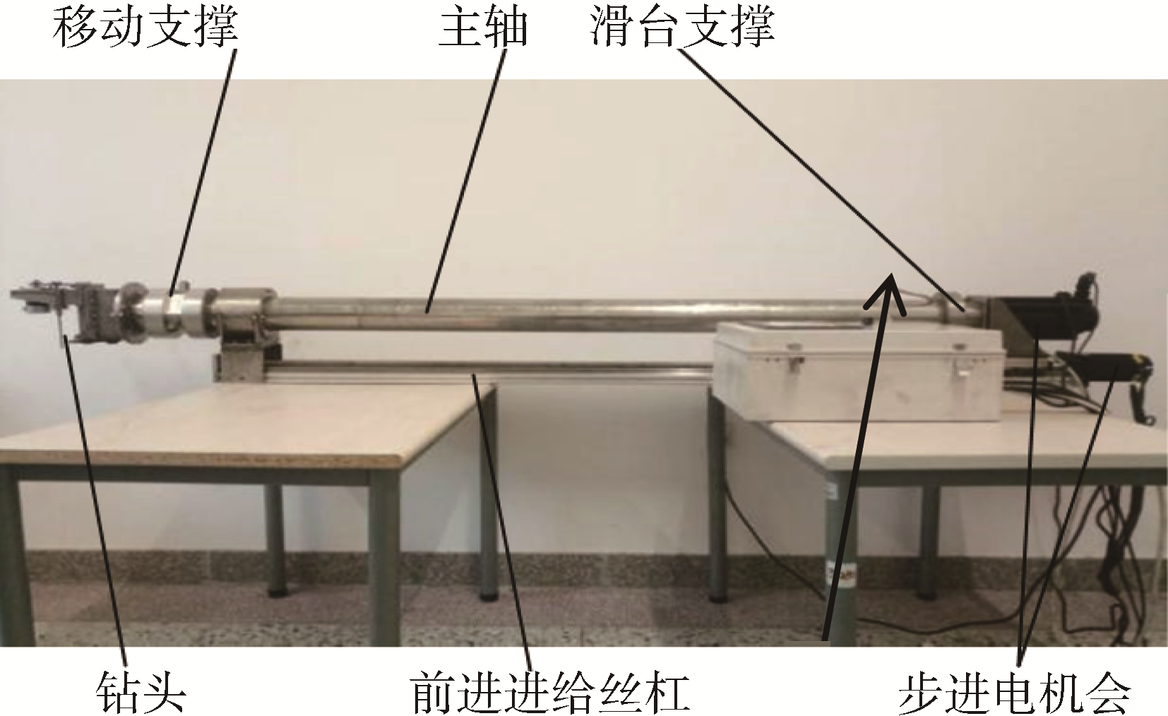
1 钻孔机器人设计与运动可达空间从钻孔机器人实际作业工况出发,其整体设计见图 1,主要由移动支撑、主轴、滑台支撑、钻头、前进进给丝杠及步进电机等组成。完成岩孔内部指定位置钻孔,需进行4个动作,且能准确定位:1)沿岩孔轴线的轴向进给运动;2)主轴的旋转运动;3)钻头旋转运动;4)钻头径向进给运动。
|
Download:
|
| 图 1 钻孔机器人 Fig. 1 The drilling robot sample | |
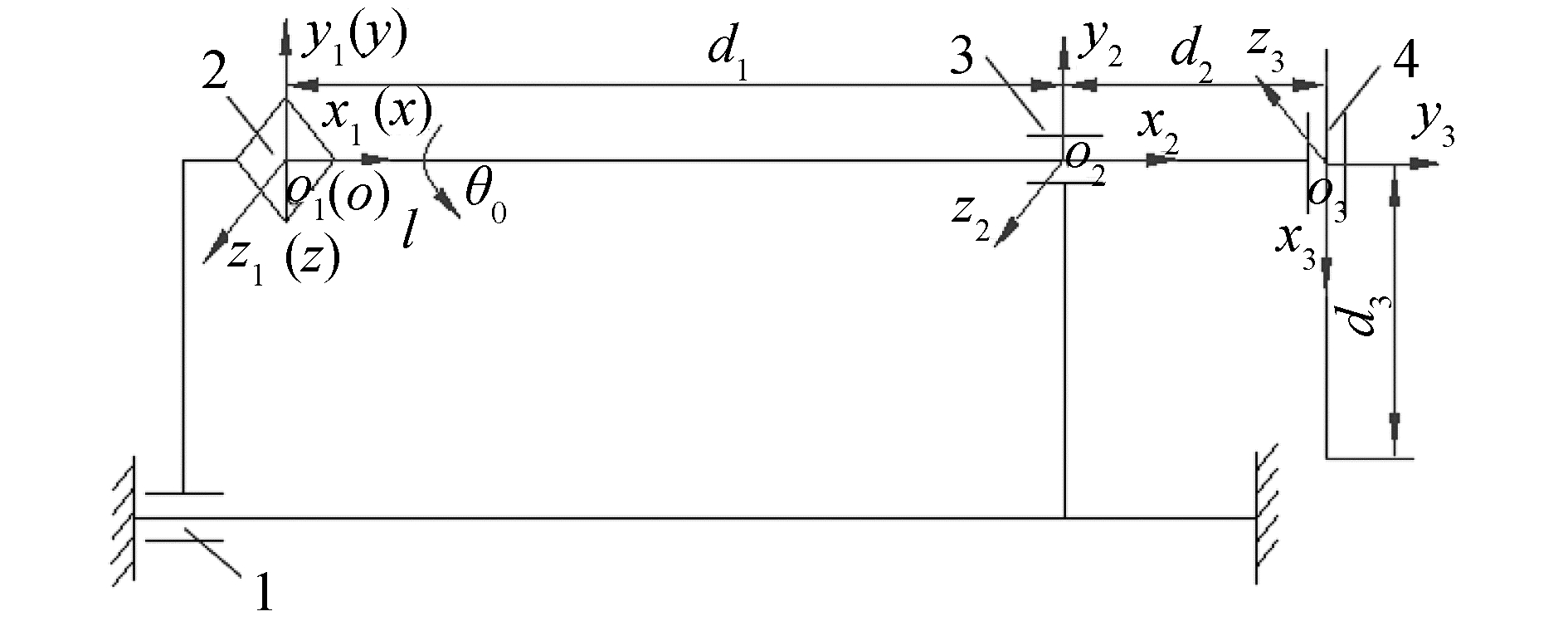
建立机器人钻头尖点运动简图,按照具体参数,关节θ0为0~360°,坐标原点距离d1为2 000 mm,坐标原点水平距离d2为400 mm,坐标原点到钻头端部距离d3为99 mm,理论上可确定运动学规律,获得尖点可达空间[10-11]。机构运动学坐标系如图 2所示。
|
Download:
|
| 图 2 钻孔机器人机构简图 Fig. 2 The drilling robot mechanism diagram | |
设钻头尖部所能到达的空间点位置在局部坐标系o3-x3y3z3中的坐标为3P=(x3, 0, z3)T,则它在固定坐标系中的表示为:
| $ \left[ {\begin{array}{*{20}{l}} P\\ 1 \end{array}} \right] = _1^0\mathit{\boldsymbol{T}}_2^1\mathit{\boldsymbol{T}}_3^2\mathit{\boldsymbol{T}}\left[ {\begin{array}{*{20}{c}} {^3P}\\ 1 \end{array}} \right] = \left[ {\begin{array}{*{20}{c}} {l + {d_1} + {d_2}}\\ { - {x_3}{\rm{cos}}{\kern 1pt} {\kern 1pt} {\kern 1pt} {\theta _0} - {z_3}{\rm{sin}}{\kern 1pt} {\kern 1pt} {\kern 1pt} {\theta _0}}\\ { - {x_3}{\rm{sin}}{\kern 1pt} {\kern 1pt} {\kern 1pt} {\theta _0} + {z_3}{\rm{cos}}{\kern 1pt} {\kern 1pt} {\kern 1pt} {\theta _0}} \end{array}} \right] $ | (1) |
式中:l为o1-x1y1z1坐标沿固定坐标系x轴移动量,0 mm≤l≤2 000 mm;10T,21T, 32T为:
| $ {_1^0}\mathit{\boldsymbol{T}} = \left[ {\begin{array}{*{20}{c}} 1&0&0&l\\ 0&{{\rm{cos}}{\kern 1pt} {\kern 1pt} {\kern 1pt} {\theta _0}}&{ - {\rm{sin}}{\kern 1pt} {\kern 1pt} {\kern 1pt} {\theta _0}}&0\\ 0&{{\rm{sin}}{\kern 1pt} {\kern 1pt} {\kern 1pt} {\theta _0}}&{{\rm{cos}}{\kern 1pt} {\kern 1pt} {\kern 1pt} {\theta _0}}&0\\ 0&0&0&1 \end{array}} \right] $ |
| $ _2^1\mathit{\boldsymbol{T}} = \left[ {\begin{array}{*{20}{c}} 1&0&0&{{d_1}}\\ 0&1&0&0\\ 0&0&1&0\\ 0&0&0&1 \end{array}} \right],_3^2\mathit{\boldsymbol{T}} = \left[ {\begin{array}{*{20}{c}} 0&1&0&{{d_2}}\\ { - 1}&0&0&0\\ 0&0&1&0\\ 0&0&0&1 \end{array}} \right] $ |
钻头尖部3P点坐标分量d3≤x3≤d3+91,即x3范围为99~190 mm,θ0的取值范围为0°~360°。通过蒙特卡罗法求出隧道支护钻孔机器人的工作空间,得出钻头的可达工作空间(如图 3所示)。理论上钻头可以实现锚杆安装孔的钻孔位置和孔洞空间要求,但是实际钻进时,其钻孔的质量会受到各种因素的影响。

|
Download:
|
| 图 3 钻头可达空间 Fig. 3 The reachable working space of the drill bit | |
从力学分析,振动是最大的影响因素(管道细而长为重点原因),应首先予以考虑[12-13]。通过机器人实际振动状态分析,找出影响质量的关键因素,为控制机器人运动提供理论依据。
2.1 振动基本模型图 4为牛眼轮支撑着的钻孔机器人模型,由于整个结构基本上是圆筒形不锈钢管做主轴,变形量较小,可近似地把它看成刚体,结合实际的装配图,机器人振动模型可为末端铰接杆机构的力学模型。

|
Download:
|
| 图 4 力学模型 Fig. 4 The mechanical model | |
假设沿着x轴的水平位置为静平衡位置,钻头轴向力FF是一个变力,设整个机器人绕O点微幅振动[7],并假设杆顺时针偏转了θ,并将θ作为广义坐标,2个弹簧K1和K2对O的力矩为逆时针方向,力FF也是逆时针方向,则可以得出:
| $ \left\{ {\begin{array}{*{20}{l}} {{F_1} = {k_1}{L_2}{\rm{sin}}{\kern 1pt} {\kern 1pt} {\kern 1pt} \theta }\\ {{F_2} = {k_2}{L_3}{\rm{sin}}{\kern 1pt} {\kern 1pt} {\kern 1pt} \theta } \end{array}} \right. $ | (2) |
式中:k1为弹簧k1的刚度,N/mm;k2为弹簧k2的刚度,N/mm;F1、F2为弹簧k1、k2的弹力,N;θ为杆偏转角度,rad;L2、L3为机械人固定尺寸。
由式(2)和动量矩定理
| $ ML_1^2\ddot \theta = - {F_1}{L_2}{\rm{cos}}{\kern 1pt} {\kern 1pt} {\kern 1pt} \theta - {F_2}{L_3}{\rm{cos}}{\kern 1pt} {\kern 1pt} {\kern 1pt} \theta - {F_F}{L_4}{\rm{cos}}{\kern 1pt} {\kern 1pt} {\kern 1pt} \theta $ | (3) |
钻头在工作的时候,受到岩石对它的轴向力为Ff,钻头受到的力是随时间按正弦规律变化的,即:
| $ {F_F} = {F_f}{\rm{sin}}(wt) $ | (4) |
式中:Ff为计算钻头轴向力,N;FF为假定钻头轴向力,N;w为角频率,rad/s。
联立式(2)~(4),有:
| $ \begin{array}{*{20}{l}} {ML_1^2\ddot \theta = - {k_1}L_2^2{\rm{sin}}{\kern 1pt} {\kern 1pt} {\kern 1pt} \theta \cdot {\rm{cos}}{\kern 1pt} {\kern 1pt} {\kern 1pt} \theta - {k_2}L_3^2{\rm{sin}}{\kern 1pt} {\kern 1pt} {\kern 1pt} \theta \cdot {\rm{cos}}{\kern 1pt} {\kern 1pt} {\kern 1pt} \theta - }\\ {{\kern 1pt} {\kern 1pt} {\kern 1pt} {\kern 1pt} {\kern 1pt} {\kern 1pt} {\kern 1pt} {\kern 1pt} {\kern 1pt} {\kern 1pt} {\kern 1pt} {\kern 1pt} {\kern 1pt} {\kern 1pt} {\kern 1pt} {\kern 1pt} {\kern 1pt} {\kern 1pt} {\kern 1pt} {\kern 1pt} {\kern 1pt} {\kern 1pt} {\kern 1pt} {\kern 1pt} {\kern 1pt} {\kern 1pt} {\kern 1pt} {\kern 1pt} {\kern 1pt} {\kern 1pt} {\kern 1pt} {\kern 1pt} {\kern 1pt} {\kern 1pt} {\kern 1pt} {\kern 1pt} {\kern 1pt} {\kern 1pt} {\kern 1pt} {F_f}{L_4}{\rm{sin}}{\kern 1pt} {\kern 1pt} (wt) \cdot {\rm{cos}}{\kern 1pt} {\kern 1pt} {\kern 1pt} \theta } \end{array} $ | (5) |
由于微幅振动,
| $ ML_1^2\ddot \theta = - {k_1}L_2^2\theta - {k_2}L_3^2\theta - {F_f}{L_4}{\rm{sin}}{\kern 1pt} (wt) $ | (6) |
式(6)为一个二阶常系数非齐次线性微分方程,将方程(6)变换成:
| $ \ddot \theta + \left( {\frac{{{k_1}L_2^2}}{{ML_1^2}} + \frac{{{k_2}L_3^2}}{{ML_1^2}}} \right)\theta = - \frac{{{F_f}{L_4}{\rm{sin}}(wt)}}{{ML_1^2}} $ | (7) |
从式(7)中可以看出,这其实是一个无阻尼强迫振动方程,其对应的齐次方程为:
| $ \ddot \theta + \left( {\frac{{{k_1}L_2^2}}{{ML_1^2}} + \frac{{{k_2}L_3^2}}{{ML_1^2}}} \right)\theta = 0 $ | (8) |
其通解为:
| $ \left\{ {\begin{array}{*{20}{l}} {k = \sqrt {\left( {\frac{{{k_1}L_2^2}}{{ML_1^2}} + \frac{{{k_2}L_3^2}}{{ML_1^2}}} \right)} }\\ {\theta = {C_1}{\rm{cos}}(kt) + {C_2}{\rm{sin}}(kt)} \end{array}} \right. $ | (9) |
式中:k为固有角频率,rad/s;C1、C2为任意常数。
对式(9)进行以下w=k和w≠k2种情况的分析和讨论,即:
1) 当w=k时,可设特解为:
| $ \theta _2^* = t({a_2}{\rm{cos}}(wt) + {b_2}{\rm{sin}}(wt)) $ | (10) |
将式(11)代入式(10),求得:
| $ \left\{ {\begin{array}{*{20}{l}} {{a_2} = \frac{{{F_f}{L_4}}}{{2ML_1^2k}}}\\ {{b_2} = 0} \end{array}} \right. $ | (11) |
由式(10)、(11)得出特解:
| $ \theta _2^* = \frac{{{F_f}{L_4}}}{{2ML_1^2k}}t{\rm{cos}}(wt) $ | (12) |
从而当w=k时,式(9)的通解为:
| $ \theta = {C_1}{\rm{cos}}(kt) + {C_2}{\rm{sin}}(kt) + \frac{{{F_f}{L_4}}}{{2ML_1^2k}}t{\rm{cos}}(wt) $ | (13) |
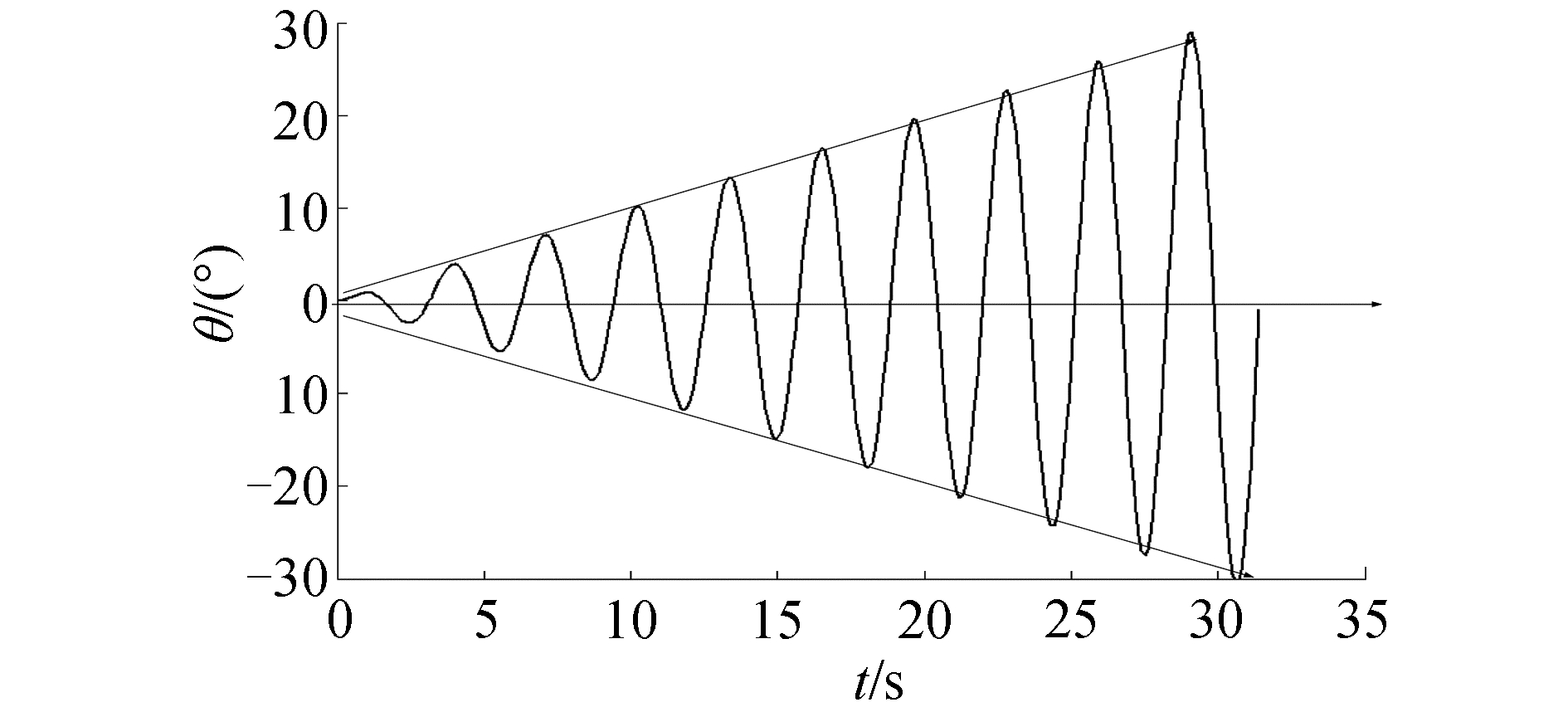
式中:θ由2部分组成,自由振动部分和强迫振动部分,强迫振动振幅中的项t/2k,说明强迫振动振幅和时间成正比。如图 5所示发生了所谓的共振现象。共振的产生会对岩石钻孔产生严重的后果,会使钻头的寿命大为减短,甚至还会使钻头发生断裂,造成钻孔失败。因此,严格控制钻头轴向力的角频率w和钻孔机器人系统的固有频率k相同,或错开这2个频率,避免出现共振。
|
Download:
|
| 图 5 w=k时的共振 Fig. 5 The resonance phenomenon as w=k | |
2) 当w≠k时,可设特解为:
| $ \theta _1^* = {a_1}{\rm{cos}}(wt) + {b_1}{\rm{sin}}(wt) $ | (14) |
将式(14)代入式(9),求得:
| $ \left\{ {\begin{array}{*{20}{l}} {{a_1} = 0}\\ {{b_1} = - \frac{{{F_f}{L_4}}}{{ML_1^2({k^2} - {w^2})}}} \end{array}} \right. $ | (15) |
由式(14)、(15)得出特解:
| $ \theta _1^* = - \frac{{{F_f}{L_4}}}{{ML_1^2({k^2} - {w^2})}}{\rm{sin}}(wt) $ | (16) |
从而当w≠k时,式(9)的通解为:
| $ \theta = {C_1}{\rm{cos}}(kt) + {C_2}{\rm{sin}}(kt) - \frac{{{F_f}{L_4}}}{{ML_1^2({k^2} - {w^2})}}{\rm{sin}}(wt) $ | (17) |
式(17)表明,在钻孔过程中,其振动可以看成2部分组成,即自由振动和强迫振动,强迫振动是由岩石对钻头轴向力引起的角频率w。当角频率w和钻孔机器人系统的固有频率k相差不大的时候,1/(k2-w2)将会趋向于无穷大,会使钻头产生严重的冲击和碰撞,不但影响到钻孔质量,也会使整个钻孔机器人结构遭到破坏。
钻孔机器人系统结构中,必须使w≠k,即:
| $ \left\{ {\begin{array}{*{20}{l}} {k = \sqrt {\left( {\frac{{{k_1}L_2^2}}{{ML_1^2}} + \frac{{{k_2}L_3^2}}{{ML_1^2}}} \right)} }\\ {\theta = {C_1}{\rm{cos}}(kt) + {C_2}{\rm{sin}}(kt) - \frac{{{F_f}{L_4}}}{{ML_1^2({k^2} - {w^2})}}{\rm{sin}}(wt)} \end{array}} \right. $ | (18) |
运用式(18),对微幅振动的角度θ和C点的振幅可进一步进行计算和优化。
有
| $ \left\{ {\begin{array}{*{20}{l}} {{C_1} = 0}\\ {{C_2} = \frac{{{F_f}{L_4}w}}{{ML_1^2k({k^2} - {w^2})}} + \frac{{{w_0}}}{k}} \end{array}} \right. $ | (19) |
图 4中C点沿着y方向的振动量
| $ \left\{ {\begin{array}{*{20}{l}} {k = \sqrt {\left( {\frac{{{k_1}L_2^2}}{{ML_1^2}} + \frac{{{k_2}L_3^2}}{{ML_1^2}}} \right)} }\\ {\theta (t) = \frac{{{F_f}{L_4}}}{{ML_1^2({k^2} - {w^2})}}\left( {\frac{w}{k}{\rm{sin}}(kt) - {\rm{sin}}(wt)} \right) + }\\ {{\kern 1pt} {\kern 1pt} {\kern 1pt} {\kern 1pt} {\kern 1pt} {\kern 1pt} {\kern 1pt} {\kern 1pt} {\kern 1pt} {\kern 1pt} {\kern 1pt} {\kern 1pt} \frac{{{w_0}}}{k}{\rm{sin}}(kt)}\\ {{y_c}(\theta ) = {L_4}{\rm{sin}}{\kern 1pt} {\kern 1pt} {\kern 1pt} \theta } \end{array}} \right. $ | (20) |
从式(20)可以看出,当θ(t)最大时,即使微幅振动的角度达到最大,则要满足:
| $ kt - wt = (2n + 1)\pi (n = 0,1,2,3, \cdots ) $ | (21) |
将式(21)代入式(20)中,则有:
| $ \left\{ {\begin{array}{*{20}{l}} {k = \sqrt {\left( {\frac{{{k_1}L_2^2}}{{ML_1^2}} + \frac{{{k_2}L_3^2}}{{ML_1^2}}} \right)} }\\ {{\theta _{{\rm{max}}}} = \frac{{{F_f}{L_4}}}{{ML_1^2({k^2} - {w^2})}}\left( {\frac{w}{k} + 1} \right) + \frac{{{w_0}}}{k}{\rm{sin}}{\kern 1pt} {\kern 1pt} kt}\\ {{y_c}({\theta _{{\rm{max}}}}) = {L_4}{\rm{sin}}{\kern 1pt} {\kern 1pt} {\kern 1pt} {\theta _{{\rm{max}}}}} \end{array}} \right. $ | (22) |
式中:θmax为微幅振动的最大振动角度,rad;yc(θmax)为C点沿着y轴的最大振幅,mm。
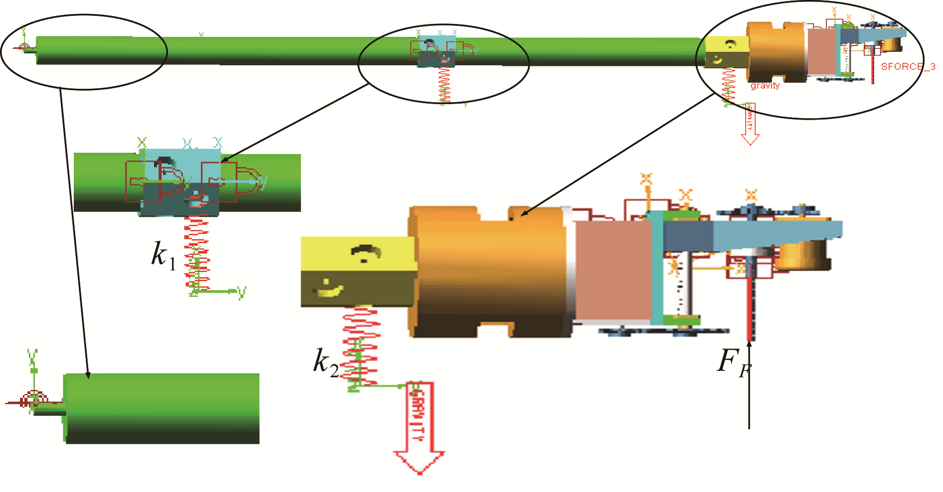
2.2 振动仿真Adams仿真[14]力学模型如图 6所示,其中仿真参数据k1=192.7 N/mm和k2=240 N/mm 2个刚度值,激振力Ff为式(5)中计算所得98.2 N,此时机器人装置的固有频率k=110 rad/s时,仿真结果在1)振幅为1.12 mm,振动周期2.4 s, w=60 rad/s;2)振幅为3.95 mm,振动周期0.6 s, w=110 rad/s两种情况下模拟。
|
Download:
|
| 图 6 Adams仿真模型 Fig. 6 The Adams simulation model | |
可见,情况2)中振幅已经大于1.12的3倍多,显然发生了共振,可见激振力角频率w不应与系统固有角频率k相等或接近。
进一步可以计算横向进给位移与k的关系为:
| $ k = \sqrt {(g{L_1}{L_3}/{L_0})} $ | (23) |
式中:g为重力加速度,取值为9.8 m/s2,L0为1 mm为牛眼轮弹簧安装位移,由式(23)可以控制钻进前进时的支撑位置,使得w≠k。
2.3 钻头电机转速与径向进给电机转速匹配钻头转速与径向进给量之间的匹配状况会影响钻孔过程的稳定性,关系到钻头的耐用度以及钻孔的质量和效率,可通过钻头与径向进给电机转速匹配关系来实现钻孔质量的稳定。钻头切削扭矩为:
| $ M = 9.81{C_M}{d^2}{f^{0.8}}{k_M} = {M^\prime }{i_1}/S $ | (24) |
式中:CM为钻削扭矩系数;f为钻头每转进给量;kM为修正系数;M′为电机额定扭矩;i1为传动比;S为安全系数。
钻头及径向的进给量为:
| $ {{V_1} = {n_1}f} $ |
径向进给量为:
| $ {{V_2} = {P_h}{n_2}/{i_2}} $ |
式中:n1为钻头电机转速;Ph丝杠导程;n2为进给电机转速;i1为传动比。
控制V1=V2,推出钻头电机转速与进给电机转速的匹配关系为:
| $ {n_2} = \frac{{{n_1}{i_2}{{\left( {\frac{{{M^\prime }{i_1}/S}}{{9.81{C_M}{d^2}{k_M}}}} \right)}^{\frac{1}{{0.8}}}}}}{{{P_h}{i_1}}} $ | (25) |
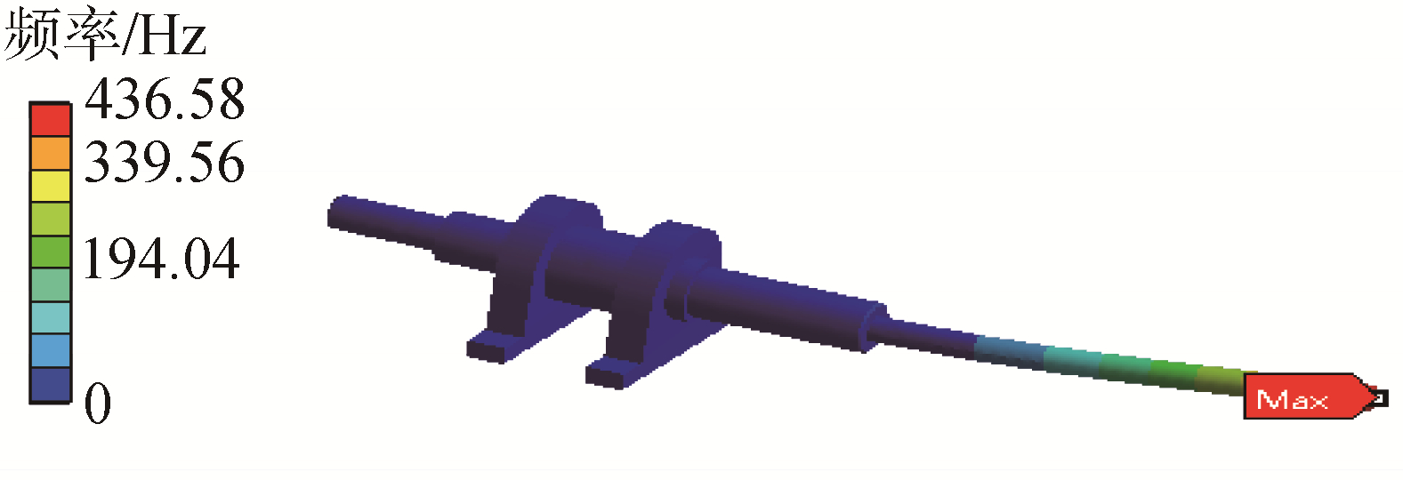
钻头转速要与进给速度进行匹配,同时避开其临界转速,钻头作为回转部件,钻孔时会受到离心力的影响,固有频率与静止时相比会有一定不同,所以要对其进行有预应力作用下的模态分析[15-18],以确定钻头工作时各个模态下的固有频率及临界转速,避免发生共振现象。将实际钻进尺寸、速度进行计算获得其前2阶振型计算云图见图 7。
|
Download:
|
| 图 7 模态第2阶计算云图 Fig. 7 The first two modes of the cloud pattern | |
前2阶的固有频率ω1、ω2分别为449.85 Hz,451.1 Hz,转子临界转速等于60倍的固有频率,为53 982 r/min钻头电机临界转速n3,可以看出钻头旋转电机额定转速远小于临界转速。因此,钻头不会发生共振现象。
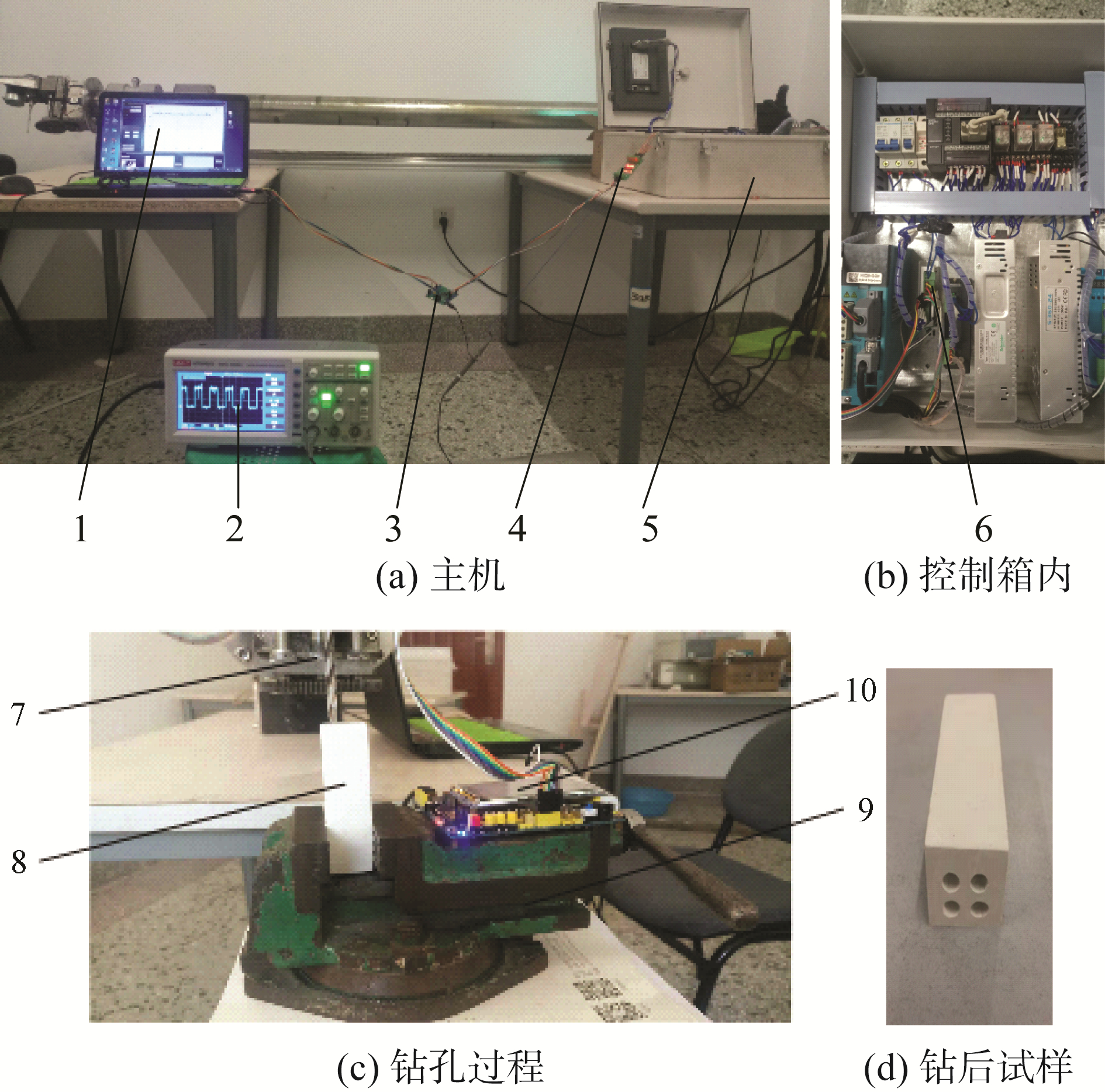
3 机器人钻孔实验本文研制开发了小型侧壁钻孔机器人及配套测试实验装置(见图 8),进行了实际钻孔的实验,主要进行钻头速度匹配实验、振动实验,并进行了钻孔的质量检测。
|
Download:
|
| 图 8 钻孔实验 Fig. 8 Drilling test experiment 注:1.主机;2.示波器;3.STM32-1单片机;4.光电耦合器;5.控制箱;6.驱动霍尔端口;7.钻头;8.岩石样品;9.夹持虎钳;10.STM32-2单片机。 | |
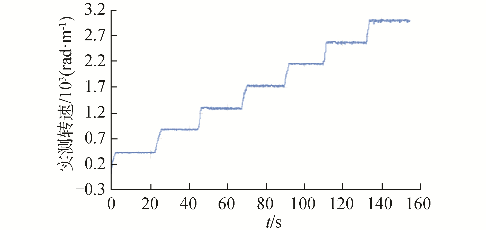
为了确保匹配的准确性,先要保证钻头电机转速调节的准确性,设定7组依次增大的占空比,利用式(13)、(14)测得7级转速曲线如图 9所示,各级转速误差小于2%,转速调节较为准确。
|
Download:
|
| 图 9 转速调节 Fig. 9 Speed adjustment | |
按照式(14)中n1和n2的关系,设定9组匹配关系进行等深度钻孔,由陀螺仪加速度计MPU6050采集钻孔位置的加速度值,通过分析加速度值,来分析钻孔实验过程是平稳的,如图 10所示。

|
Download:
|
| 图 10 加速度曲线 Fig. 10 Acceleration curves | |
钻头在整个钻孔过程中,反应钻头轴向加速度变化的加速度值在-0.2~0.2 g波动,总体上比较平稳,证明在转速匹配的情况下,钻孔过程稳定性较好。
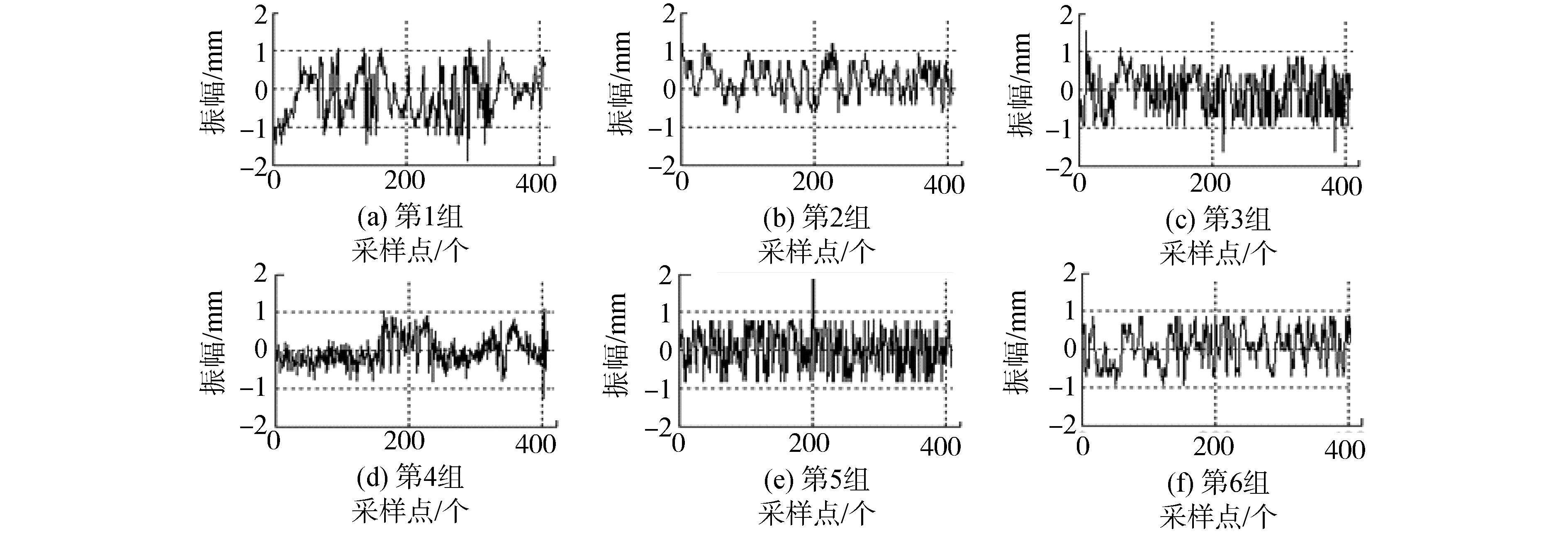
3.2 振动实验由图 4所示的力学模型可知,钻头位置的振幅z为l4sinθ,由陀螺仪加速度计MPU6050采集钻头位置的角度变化,计算得出振幅,来分析钻孔过程是否平稳,如图 11所示。
|
Download:
|
| 图 11 振幅曲线 Fig. 11 Amplitude curves | |
钻头的振幅波动大致在-1~1 mm,波动较小,钻孔过程比较稳定,未发生共振。
图 8右下面为开好的岩孔,其规格为Φ6×90 mm,采用的是Φ6钻头,4个钻孔实际测量的平均尺寸为Φ6.2×90.5 mm,满足打锚杆孔洞要求。
4 结论1) 建立了振动力学的理论模型,为实现良好的钻孔质量,应该避免发生共振现象,理论计算值为w≠k。
2) 推导了电机匹配速度控制方程,建立了钻头钻进速度与进给速度和实验岩石材料关系,为适应相似岩石工况环境的钻孔推进控制提供依据。
3) 为使钻孔质量可控制,在实际设计中应保证进给位移支点控制,配合速度匹配控制等控制器设计,从而更好保证钻孔质量。
4) 以理论计算为基础,研制了一种小型钻孔机器人,并完成了其钻孔实验验证,理论与实验结果表明研制的小型钻孔机器人能够满足模拟系统的钻孔功能需求,可为受限条件的相关机器人设备研制提供参考。
| [1] |
LI Xibing, GONG Fengqiang, TAO Ming, et al. Failure mechanism and coupled static-dynamic loading theory in deep hard rock mining:a review[J]. Journal of rock mechanics and geotechnical engineering, 2017, 9(4): 767-782. DOI:10.1016/j.jrmge.2017.04.004 (  0) 0)
|
| [2] |
MA Hongsu, GONG Qiuming, WANG Ju, et al. Study on the influence of confining stress on TBM performance in granite rock by linear cutting test[J]. Tunnelling and underground space technology, 2016, 57: 145-150. DOI:10.1016/j.tust.2016.02.020 (  0) 0)
|
| [3] |
LI Xibing, LI Chongjin, CAO Wenzhuo, et al. Dynamic stress concentration and energy evolution of deep-buried tunnels under blasting loads[J]. International journal of rock mechanics and mining sciences, 2018, 104: 131-146. (  0) 0)
|
| [4] |
钱七虎. 地下工程建设安全面临的挑战与对策[J]. 岩石力学与工程学报, 2012, 31(10): 1945-1956. QIAN Qihu. Challenges faced by underground projects construction safety and countermeasures[J]. Chinese journal of rock mechanics and engineering, 2012, 31(10): 1945-1956. (  0) 0)
|
| [5] |
李永芳. 全断面岩石隧洞掘进机在特殊地质洞段的施工[J]. 水利水电工程设计, 2012, 31(3): 19-21. LI Yongfang. TBM construction of special gedogical full-section rock tunnel tunneliy[J]. Design of water resavrces & hydroelectric engineering, 2012, 31(3): 19-21. (  0) 0)
|
| [6] |
ZHAO Yanru, YANG Haiqing, CHEN Zhongkui, et al. Effects of jointed rock mass and mixed ground conditions on the cutting efficiency and cutter wear of tunnel boring machine[J]. Rock mechanics and rock engineering, 2019, 52(5): 1303-1313. DOI:10.1007/s00603-018-1667-y (  0) 0)
|
| [7] |
JI Feng, SHI Yuchuan, LI Renjie, et al. Modified Q-index for prediction of rock mass quality around a tunnel excavated with a tunnel boring machine (TBM)[J]. Bulletin of engineering geology and the environment, 2019, 78(5): 3755-3766. (  0) 0)
|
| [8] |
张忠林, 周雪鹏, 周辉, 等.一种岩石全断面加载装置: 中国, CN201610309168.X[P]. 2016-08-31. ZHANG Zhonglin, ZHOU Xuepeng, ZHOU Hui, et al. Full-section loading device for rocks: CN, CN201610309168.X[P]. 2016-08-31. (  0) 0)
|
| [9] |
张忠林, 洪维, 周辉, 等.一种隧道支护钻孔机器人: 中国, CN201610309170.7[P]. 2017-11-21. ZHANG Zhonglin, HONG Wei, ZHOU Hui, et al. Tunnel supporting drilling robot: CN, CN201610309170.7[P]. 2017-11-21. (  0) 0)
|
| [10] |
RASTGAR H, NAEIMI H R, AGHELI M. Characterization, validation, and stability analysis of maximized reachable workspace of radially symmetric hexapod machines[J]. Mechanism and machine theory, 2019, 137: 315-335. DOI:10.1016/j.mechmachtheory.2019.01.033 (  0) 0)
|
| [11] |
MAZARE M, TAGHIZADEH M. Geometric optimization of a delta type parallel robot using harmony search algorithm[J]. Robotica, 2019, 37(9): 1494-1512. DOI:10.1017/S0263574719000080 (  0) 0)
|
| [12] |
GUL U, AYDOGDU M. Vibration analysis of Love nanorods using doublet mechanics theory[J]. Journal of the Brazilian society of mechanical sciences and engineering, 2019, 41(8): 351. DOI:10.1007/s40430-019-1849-x (  0) 0)
|
| [13] |
AIPLE M, SMISEK J, SCHIELE A. Increasing impact by mechanical resonance for teleoperated hammering[J]. IEEE transactions on haptics, 2019, 12(2): 154-165. (  0) 0)
|
| [14] |
ERKAYA S. Determining power consumption using neural model in multibody systems with clearance and flexible joints[J]. Multibody system dynamics, 2019, 47(2): 165-181. DOI:10.1007/s11044-019-09682-4 (  0) 0)
|
| [15] |
向万龙. 机械振动分析及研究方法综述[J]. 科技展望, 2016, 26(13): 59. XIANG Wanlong. Summary of mechanical vibration analysis and research methods[J]. Technology outlook, 2016, 26(13): 59. (  0) 0)
|
| [16] |
SAESSI M, ALIZADEH A, ABDOLLAHI A. On the analysis of fracture mechanisms and mechanical behavior of AA5083-based tri-modal composites reinforced with 5 wt.%B4C and toughened by AA5083 and AA2024 coarse grain phases[J]. Advanced powder technology, 2019, 30(9): 1754-1764.
(  0) 0)
|
| [17] |
LUNDBERG B, HUO J. Biconvex versus bilinear force-penetration relationship in percussive drilling of rock[J]. International journal of impact engineering, 2017, 100: 7-12. DOI:10.1016/j.ijimpeng.2016.10.002 (  0) 0)
|
| [18] |
ASIABAR A N, KAZEMI R. A direct yaw moment controller for a four in-wheel motor drive electric vehicle using adaptive sliding mode control[J]. Proceedings of the institution of mechanical engineers, part K:journal of multi-body dynamics, 2019, 233(3): 549-567. DOI:10.1177/1464419318807700 (  0) 0)
|
 2020, Vol. 41


