2. 西安测绘研究所,西安市雁塔路中段1号,710054
GNSS坐标时间序列中包含各种因素引起的非线性变化,如何定量分析和有效分离不同因素对时间序列非线性变化的影响,是GNSS坐标时间序列分析领域的热点和难点之一。GNSS坐标时间序列中的非线性变化可分为3类:一是虚假的非线性变化,主要由GNSS数据处理模型不完善或其他系统误差引起,如GNSS交点年周期误差、天线相位中心模型误差等[1-4];二是真实的基准站非线性运动,如海洋及大气潮汐、环境负载、基岩及观测墩热膨胀效应等[5-8];三是其他未知因素引起的形变。其中,包括基准站天线观测墩及其所在基岩在内的热弹性形变是时间序列中非线性信号的贡献源之一。
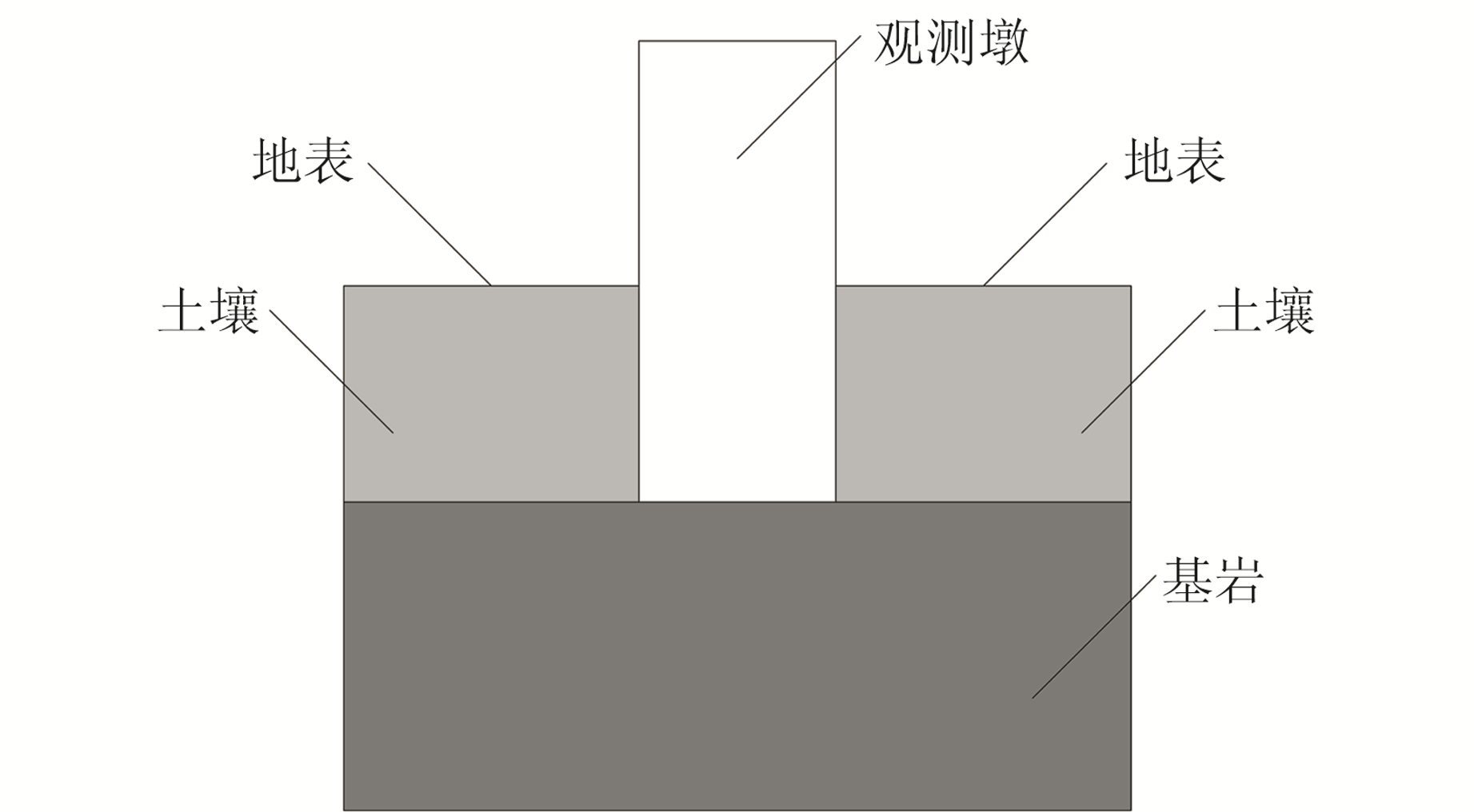
通常情况下,GNSS观测墩的一端会直接固连在基岩上或具有稳定结构的建筑物顶端,常见的观测墩材质包括水泥(观测墩)、铁(桁架)、钢(管)、铝合金(桅杆)等(图 1)。温度变化对GNSS台站位移的影响可以分为两个部分:一是地表温度变化通过热传递引起的基岩热膨胀效应,二是GNSS观测墩温度变化引起的热胀冷缩效应[9]。针对基岩受温度变化产生的位移,目前有两种分析方法:基于弹性半空间的热弹性形变模型[10-11]和基于统一的、三维球体的热弹性形变模型[12]。针对观测墩的温度变化,一般的处理方法如下[8]:将空气温度变化作为观测墩内部温度变化,并且假设观测墩是一维结构,只存在轴向的形变,温度变化只引起GNSS天线观测墩地面以上部分的垂向位移。这种处理方法存在两个缺陷:一是观测墩并非一维结构,温度的变化不仅会引起观测墩的垂向位移,还会引起水平位移;二是目前的线性模型仅考虑观测墩地表以上部分的垂向形变,但观测墩与基岩的热传导系数等材料参数并不一致,因此作为一个整体考虑并不符合实际。基于上述理论,利用弹性力学及热弹性力学相关理论,对轴对称观测墩在一维温度场下的热弹性问题进行分析建模,得到观测墩位移的解析解。

|
图 1 观测墩 Fig. 1 Monument |
在进行GNSS台站位移热弹性效应建模时,会用到以下弹性力学基本假定[13]:连续性假定、完全弹性假定、均匀性假定、各向同性假定和小变形假定。
1.2 热弹性形变建模几何方程、物理方程和平衡微分方程是弹性力学的3个基本方程,其中几何方程描述位移和应变之间的关系,物理方程描述应力和应变之间的关系,平衡微分方程描述应力和体力之间的关系。对于圆柱形观测墩,宜采用柱坐标(r, φ, z)确定空间点的位置(图 2)。

|
图 2 柱坐标系 Fig. 2 Cylindrical coordinate system |
空间轴对称的几何方程为[13]:
| $ \left\{\begin{array}{l} \varepsilon_{r}=\frac{\partial u}{\partial r} \\ \varepsilon_{\varphi}=\frac{u}{r} \\ \varepsilon_{z}=\frac{\partial w}{\partial z} \\ \gamma_{z r}=\frac{\partial w}{\partial r}+\frac{\partial u}{\partial z} \end{array}\right. $ | (1) |
式中,u、w为径向和轴向的位移,εr、εφ、εz、γzr分别为径向应变、环向应变、轴向应变和切应变。
空间轴对称的物理方程为[13]:
| $ \left\{\begin{array}{l} \varepsilon_{r}=\frac{1}{E}\left[\sigma_{r}-\mu\left(\sigma_{\varphi}+\sigma_{z}\right)+\alpha T\right] \\ \varepsilon_{\varphi}=\frac{1}{E}\left[\sigma_{\varphi}-\mu\left(\sigma_{r}+\sigma_{z}\right)+\alpha T\right] \\ \varepsilon_{z}=\frac{1}{E}\left[\sigma_{z}-\mu\left(\sigma_{r}+\sigma_{\varphi}\right)+\alpha T\right] \\ \gamma_{z r}=\frac{\tau_{z r}}{G}=\frac{2(1+\mu)}{E} \tau_{z r} \end{array}\right. $ | (2) |
式中,σr、σφ、σz、τzr分别为径向应力、环向应力、轴向应力和切应力,α为热膨胀系数,E为弹性模量,μ为泊松比,T为温度差。
空间轴对称的平衡微分方程为[13]:
| $ \left\{\begin{array}{l} \frac{\partial \sigma_{r}}{\partial r}+\frac{\partial \tau_{z r}}{\partial z}+\frac{\sigma_{r}-\sigma_{\varphi}}{r}=0 \\ \frac{\partial \sigma_{z}}{\partial z}+\frac{\partial \tau_{z r}}{\partial r}+\frac{\tau_{z r}}{r}=0 \end{array}\right. $ | (3) |
联立式(1)、式(2)和式(3)可得用位移表示的平衡微分方程(假设温度变化仅为轴向坐标z和时间t的函数,则
| $ \left\{\begin{array}{l} \frac{1-\mu}{1-2 \mu} \frac{\partial^{2} u}{\partial r^{2}}+\frac{1-\mu}{1-2 \mu}\left(\frac{1}{r} \frac{\partial u}{\partial r}-\frac{u}{r^{2}}\right)+ \\ \ \ \ \ \frac{1}{2(1-2 \mu)} \frac{\partial^{2} w}{\partial r \partial z}+\frac{1}{2} \frac{\partial^{2} u}{\partial z^{2}}=0 \\ \frac{1-\mu}{(1+\mu)(1-2 \mu)} \frac{\partial^{2} w}{\partial z^{2}}+\frac{1}{2(1+\mu)(1-2 \mu)}\cdot \\ \frac{\partial^{2} u}{\partial r \partial z}+\frac{1}{2(1+\mu)} \frac{\partial^{2} w}{\partial r^{2}}+\frac{1}{2(1+\mu)(1-2 \mu)}\cdot \\ \frac{1}{r} \frac{\partial u}{\partial z}+\frac{1}{2(1+\mu)} \frac{1}{r} \frac{\partial w}{\partial r}-\frac{\alpha}{1-2 \mu} \frac{\partial T}{\partial z}=0 \end{array}\right. $ | (4) |
将观测墩地表以上部分与地表以下部分分开考虑:
1) 对于观测墩地表以上部分(向上为z轴正方向),假定地表以上部分观测墩温度与地表温度变化一致(即温度T是时间的函数,与轴向坐标z和径向坐标r无关),则τzr=0,可将式(4)进一步简化为:
| $ \left\{\begin{array}{l} (1-\mu) \frac{\partial^{2} u}{\partial r^{2}}+\mu \frac{\partial^{2} w}{\partial r \partial z}+(1-\mu) \cdot \\ \ \ \ \ \frac{1}{r}\left(\frac{\partial u}{\partial r}-\frac{u}{r}\right)=0 \\ (1-\mu) \frac{\partial^{2} w}{\partial z^{2}}+\mu\left(\frac{\partial^{2} u}{\partial r \partial z}+\frac{1}{r} \frac{\partial u}{\partial z}\right)=0 \end{array}\right. $ | (5) |
边界条件为:
| $ \left\{\begin{array}{l} z=0, w=0 \\ z=l_{1}, \sigma_{z}=0 \\ r=R, \sigma_{R}=0 \\ r=0, u=0 \end{array}\right. $ | (6) |
式中,l1为观测墩地表以上部分的高度,R为观测墩半径。将边界条件式(6)代入式(5)可得:
| $ \left\{\begin{array}{l} w=\alpha T z \\ u=\alpha T r \end{array}\right. $ | (7) |
因此,可得地表以上部分观测墩产生的垂向位移为:
| $ w_{\text {above }}=\alpha T l_{1} $ | (8) |
2) 地表以下部分观测墩中的温度随深度的分布为[14]:
| $ \begin{gathered} T(z, t)=\bar{T}+\sum\limits_{i=1}^{N} A_{i} \mathrm{e}^{-z \sqrt{\omega_{i} / 2 k}} \cdot\\ \cos \left(\omega_{i} t-z \sqrt{\omega_{i} / 2 k}-\varphi_{i}\right) \end{gathered} $ | (9) |
式中,T为一段时期内的地表平均温度,k为热传导系数(与时间t、深度z无关),N为温度变化的谐波个数,Ai、ωi、φi分别为温度第i个谐波的振幅、角频率和初始相位。
观测墩地表以下部分的边界条件为(向下为z轴正方向):
| $ \left\{\begin{array}{l} z=l_{2}, w=0 \\ z=0, \sigma_{z}=0 \\ r=R, \sigma_{r}=0 \\ r=0, u=0 \end{array}\right. $ | (10) |
式中,l2为观测墩地表以下部分的高度。由于假设温度只随深度变化,当深度相同时温度相同,因此可假定
| $ \left\{\begin{array}{l} \frac{1-\mu}{1-2 \mu} \frac{\partial^{2} u}{\partial r^{2}}+\frac{1-\mu}{1-2 \mu}\left(\frac{1}{r} \frac{\partial u}{\partial r}-\frac{u}{r^{2}}\right)+ \\ \ \ \ \ \frac{1}{2} \frac{\partial^{2} u}{\partial z^{2}}=0 \\ (1-\mu) \frac{\partial^{2} w}{\partial z^{2}}+\frac{1}{2} \frac{\partial^{2} u}{\partial r \partial z}+\frac{1}{2} \frac{1}{r} \frac{\partial u}{\partial z}- \\ \ \ \ \ \alpha(1+\mu) \frac{\partial T}{\partial z}=0 \end{array}\right. $ | (11) |
将式(9)和式(10)代入式(11),可得方程组的解:
| $ \left\{\begin{array}{l} u=\frac{1}{2} \frac{1+\mu}{1-\mu} r \sum\limits_{i=1}^{N} A_{i} \mathrm{e}^{-z \sqrt{\omega_{i} / 2 k}}\cdot \\ \ \ \ \ \cos \left(\omega_{i} t-z \sqrt{\omega_{i} / 2 k}-\varphi_{i}\right) \\ \omega=\frac{1+\mu}{1-\mu} \alpha \int \sum\limits_{i=1}^{N} A_{i} \mathrm{e}^{-z \sqrt{\omega_{i} / 2 k}} \cdot\\ \ \ \ \ \cos \left(\omega_{i} t-z \sqrt{\omega_{i} / 2 k}-\varphi_{i}\right) \mathrm{d} z \end{array}\right. $ | (12) |
因此,地表以下部分观测墩产生的位移为:
| $ \left\{\begin{array}{l} u_{\text {under }}=\frac{1}{2} \frac{1+\mu}{1-\mu} \alpha r \sum\limits_{i=1}^{N} A_{i}\left(1-\mathrm{e}^{-z \sqrt{\omega_{i} / 2 k}}\right) \cdot \\ \quad \cos \left(\omega_{i} t-z \sqrt{\omega_{i} / 2 k}-\varphi_{i}\right) \\ w_{\text {under }}=\frac{1+\mu}{1-\mu} \alpha \sum A_{i} \sqrt{\frac{k}{\omega_{i}}}\left[\cos \left(\omega_{i} t-\varphi_{i}-\frac{{\rm{ \mathsf{ π} }}}{4}\right)-\right. \\ \left.\mathrm{e}^{-l_{2} \sqrt{\omega_{i} / 2 k}} \cos \left(\omega_{i} t-\varphi_{i}-l_{2} \sqrt{\omega_{i} / 2 k}-\frac{{\rm{ \mathsf{ π} }}}{4}\right)\right] \end{array}\right. $ | (13) |
弹性半空间模型分析得到的基岩垂向位移[8]为:
| $ \begin{aligned} &w_{\text {bedrock }}=-\frac{1+\mu_{1}}{1-\mu_{1}} \alpha_{1} \sum\limits_{i=1}^{N} A_{i} \sqrt{\frac{k_{1}}{2 \omega_{i}}} \mathrm{e}^{-z \sqrt{k_{1} / 2 \omega_{i}}} \cdot\\ &\ \ \ \ {\left[\sin \left(\omega_{i} t-\varphi_{i}-z \sqrt{\frac{\omega_{i}}{2 k_{1}}}\right)+\right.} \\ &\ \ \ \ \left.\left.\cos \left(\omega_{i} t-\varphi_{i}-z \sqrt{\frac{\omega_{i}}{2 k_{1}}}\right)\right]\right|_{0} ^{\infty}= \\ &\ \ \ \ \frac{1+\mu_{1}}{1-\mu_{1}} \alpha_{1} \sum\limits_{i=1}^{N} A_{i} \sqrt{\frac{k_{1}}{\omega_{i}}} \cos \left(\omega_{i} t-\varphi_{i}-\frac{{\rm{ \mathsf{ π} }}}{4}\right) \end{aligned} $ | (14) |
式中,μ1、α1、k1分别为基岩的泊松比、热膨胀系数和热扩散系数。
若分别考虑观测墩地下部分与基岩,则基岩部分的垂向位移w′bedrock应为:
| $ \begin{gathered} w^{\prime}{}_{\text {bedrock }}=-\frac{1+\mu_{1}}{1-\mu_{1}} \alpha_{1} \sum\limits_{i=1}^{N} A_{i} \sqrt{\frac{k_{1}}{2 \omega_{i}}} \mathrm{e}^{-z \sqrt{k_{1} / 2 \omega_{i}}}\cdot \\ {\left[\sin \left(\omega_{i} t-\varphi_{i}-z \sqrt{\frac{\omega_{i}}{2 k_{1}}}\right)+\right.} \\ \left.\left.\cos \left(\omega_{i} t-\varphi_{i}-z \sqrt{\frac{\omega_{i}}{2 k_{1}}}\right)\right]\right|_{l_{2}} ^{\infty}=\frac{1+\mu_{1}}{1-\mu_{1}} \alpha_{1} \sum\limits_{i=1}^{N} A_{i} \sqrt{\frac{k_{1}}{\omega_{i}}} \cdot\\ \mathrm{e}^{-l_{2} \sqrt{\omega_{i} / 2 k_{1}}} \cos \left(\omega_{i} t-\varphi_{i}-l_{2} \sqrt{\omega_{i} / 2 k_{1}}-\frac{{\rm{ \mathsf{ π} }}}{4}\right) \end{gathered} $ | (15) |
观测墩顶端的垂向位移wimp应为观测墩地表以上部分位移wabove、地表以下部分位移wunder和基岩部分位移w′bedrock的叠加,根据式(8)、式(13)和式(15),可计算得到观测墩顶端的垂向位移为:
| $ \begin{gathered} w_{\text {imp }}=\alpha T l_{1}+\frac{1+\mu}{1-\mu} \alpha \sum\limits_{i=1}^{N} A_{i} \sqrt{\frac{k_{1}}{\omega_{i}}} \cdot \\ {\left[\cos \left(\omega_{i} t-\varphi_{i}-\frac{{\rm{ \mathsf{ π} }}}{4}\right)-\mathrm{e}^{-l_{2} \sqrt{\omega_{i} / 2 k}} \cdot\right.} \\ \left.\cos \left(\omega_{i} t-\varphi_{i}-l_{2} \sqrt{\frac{\omega_{i}}{2 k}}-\frac{{\rm{ \mathsf{ π} }}}{4}\right)\right]+\frac{1+\mu_{1}}{1-\mu_{1}} \alpha_{1} \cdot \\ \sum\limits_{i=1}^{N} A_{i} \sqrt{\frac{k_{1}}{\omega_{i}}} \mathrm{e}^{-l_{2} \sqrt{\omega_{i} / 2 k_{1}}} \cos \left(\omega_{i} t-\varphi_{i}-l_{2} \sqrt{\frac{\omega_{i}}{2 k_{1}}}-\frac{{\rm{ \mathsf{ π} }}}{4}\right) \end{gathered} $ | (16) |
文献[8]中,观测墩顶端的垂向位移为观测墩地表以上部分位移wabove与基岩位移wbedrock的和:
| $ \begin{gathered} w_{\text {cur }}=\alpha T l_{1}+\frac{1+\mu_{1}}{1-\mu_{1}} \alpha_{1} \sum\limits_{i=1}^{N} A_{i} \sqrt{\frac{k_{1}}{\omega_{i}}}\cdot \\ \cos \left(\omega_{i} t-\varphi_{i}-\frac{{\rm{ \mathsf{ π} }}}{4}\right) \end{gathered} $ | (17) |
由式(16)和式(17)可知,本文得到的观测墩地表以上部分的垂向位移与文献[8]的结果一致。对于观测墩地表以下部分,文献[8]中是将观测墩与基岩作为一个整体考虑,忽略了观测墩与基岩的热扩散系数、热膨胀系数和泊松比等参数的不一致,因此将观测墩地表以下部分与基岩分开考虑会更符合实际。此外,文献[8]还忽略了观测墩的水平位移,由于水平位移会随半径的增大而增大,因此需要将接收机安装在圆心处以消除水平位移对结果的影响。
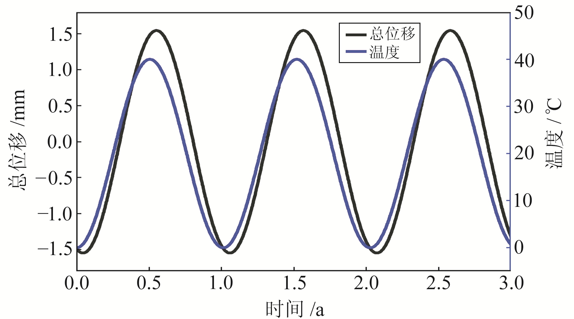
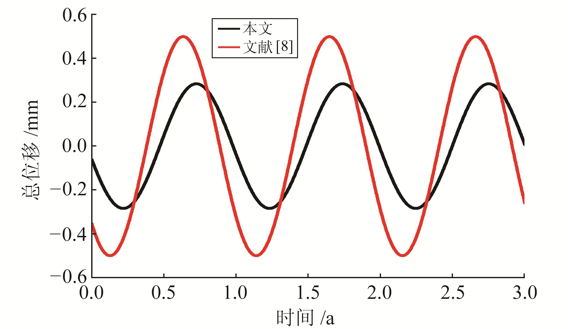
通过算例对比分析本文与文献[8]的结果。设T=20 ℃,N=1,A1=20,ω1=1.992 4×10⁻⁷ /s,φ1=π,l1=3.5 m,l2=1.8 m,基岩与观测墩的材料参数如表 1所示。总位移与温度随时间的变化如图 3所示,本文模型与文献[8]模型的基岩位移对比如图 4所示。
|
|
表 1 材料参数 Tab. 1 Parameters of materials |

|
图 3 总位移与温度随时间的变化 Fig. 3 Vertical displacement and temperature varied with time |

|
图 4 本文模型与文献[8]模型基岩位移对比 Fig. 4 The comparison of the bedrock displacement between the models in this paper and the literature [8] |
结合图 3和式(16)可知,观测墩位移随温度的升高而增大,但与温度之间存在相位延迟。由图 4可见,本文基岩位移峰值小于文献[8]峰值,相差约43%,这是由于在半无限空间模型中基岩与观测墩地表以下部分被视为一个整体,会使基岩位移偏大。结合式(14)和(15)可知,本文与文献[8]的结果之间存在一个衰减项
图 5和图 6分别为本文模型与文献[8]模型地表以下总位移和整体总位移对比,本文模型地表以下总位移和整体总位移分别比文献[8]的结果大55.1%和24.2%。这是因为本文模型中观测墩顶端的垂向位移为观测墩地表以上部分位移、地表以下部分位移和基岩部分位移之和,而文献[8]中观测墩顶端的垂向位移仅为观测墩地表以上部分位移与基岩位移之和。由于观测墩的热膨胀系数(12×10-6/℃)比基岩的热膨胀系数(6×10-6/℃)大,因此文献[8]中将观测墩与基岩作为一个整体会使总位移偏小。

|
图 5 本文模型与文献[8]模型地表以下总位移对比 Fig. 5 The comparison of vertical underground displacement between the models in this paper and the literature [8] |

|
图 6 本文模型与文献[8]模型总位移对比 Fig. 6 The comparison of vertical displacement between the models in this paper and the literature [8] |
本文基于弹性力学及热弹性力学的相关理论,通过公式推导对轴对称观测墩在一维温度场下的热弹性问题进行建模与分析,提出一种更加严密的热弹性模型,用于计算观测墩位移。结果表明:
1) 观测墩的垂向位移由观测墩及基岩的泊松比、热膨胀系数、温度差和高度共同决定。
2) 本文提出的改进模型中观测墩顶端的垂向位移为观测墩地表以上部分位移、地表以下部分位移和基岩部分位移之和,考虑了观测墩与基岩材料参数的不同,相对于文献[8]模型更符合实际,因此能更准确地估算热弹性效应对GNSS台站位移的影响。
| [1] |
Steigenberger P, Rothacher M, Schmid R, et al. Effects of Different Antenna Phase Center Models on GPS-Derived Reference Frames[A]//Drewes H. Geodetic Reference Frames, IAG Symposia 134[M]. Berlin, Heidelberg: Springer, 2008
(  0) 0) |
| [2] |
Petrie E J, King M A, Moore P, et al. Higher-Order Ionospheric Effects on the GPS Reference Frame and Velocities[J]. Journal of Geophysical Research: Solid Earth, 2010, 115(B3)
(  0) 0) |
| [3] |
Ray J, Griffiths J, Collilieux X, et al. Subseasonal GNSS Positioning Errors[J]. Geophysical Research Letters, 2013, 40(22): 5854-5860 DOI:10.1002/2013GL058160
(  0) 0) |
| [4] |
Penna N T, King M A, Stewart M P. GPS Height Time Series: Short-Period Origins of Spurious Long-Period Signals[J]. Journal of Geophysical Research: Solid Earth, 2007, 112(B2)
(  0) 0) |
| [5] |
姜卫平, 王锴华, 邓连生, 等. 热膨胀效应对GNSS基准站垂向位移非线性变化的影响[J]. 测绘学报, 2015, 44(5): 473-480 (Jiang Weiping, Wang Kaihua, Deng Liansheng, et al. Impact on Nonlinear Vertical Variation of GNSS Reference Stations Caused by Thermal Expansion[J]. Acta Geodaetica et Cartographica Sinica, 2015, 44(5): 473-480)
(  0) 0) |
| [6] |
Yan H M, Chen W, Zhu Y Z, et al. Contributions of Thermal Expansion of Monuments and nearby Bedrock to Observed GPS Height Changes[J]. Geophysical Research Letters, 2009, 36(13)
(  0) 0) |
| [7] |
Jiang W P, Li Z, Dam T, et al. Comparative Analysis of Different Environmental Loading Methods and Their Impacts on the GPS Height Time Series[J]. Journal of Geodesy, 2013, 87(7): 687-703 DOI:10.1007/s00190-013-0642-3
(  0) 0) |
| [8] |
闫昊明, 陈武, 朱耀仲, 等. 温度变化对我国GPS台站垂直位移的影响[J]. 地球物理学报, 2010, 53(4): 825-832 (Yan Haoming, Chen Wu, Zhu Yaozhong, et al. Thermal Effects on Vertical Displacement of GPS Stations in China[J]. Chinese Journal of Geophysics, 2010, 53(4): 825-832 DOI:10.3969/j.issn.0001-5733.2010.04.007)
(  0) 0) |
| [9] |
王海涛, 聂建亮, 田婕, 等. 地表温度变化对GNSS连续运行基准站垂向形变影响研究[J]. 大地测量与地球动力学, 2020, 40(11): 1170-1174 (Wang Haitao, Nie Jianliang, Tian Jie, et al. Research on Influence of Surface Temperature Change on Vertical Deformation of GNSS Continuously Operating Reference Station[J]. Journal of Geodesy and Geodynamics, 2020, 40(11): 1170-1174)
(  0) 0) |
| [10] |
Dong D, Fang P, Bock Y, et al. Anatomy of Apparent Seasonal Variations from GPS-Derived Site Position Time Series[J]. Journal of Geophysical Research: Solid Earth, 2002, 107(B4)
(  0) 0) |
| [11] |
Tsai V C. A Model for Seasonal Changes in GPS Positions and Seismic Wave Speeds Due to Thermoelastic and Hydrologic Variations[J]. Journal of Geophysical Research: Solid Earth, 2011, 116(B4)
(  0) 0) |
| [12] |
Fang M, Dong D N, Hager B H. Displacements Due to Surface Temperature Variation on a Uniform Elastic Sphere with Its Centre of Mass Stationary[J]. Geophysical Journal International, 2014, 196(1): 194-203 DOI:10.1093/gji/ggt335
(  0) 0) |
| [13] |
徐芝纶. 弹性力学[M]. 北京: 高等教育出版社, 2016 (Xu Zhilun. Elasticity[M]. Beijing: Higher Education Press, 2016)
(  0) 0) |
| [14] |
Verhoef A, Hurk B J J M, Jacobs A F G, et al. Thermal Soil Properties for Vineyard(EFEDA-I) and Savanna(HAPEX-Sahel) Sites[J]. Agricultural and Forest Meteorology, 1996, 78(1-2): 1-18 DOI:10.1016/0168-1923(95)02254-6
(  0) 0) |
2. Xi'an Research Institute of Surveying and Mapping, 1 Mid-Yanta Road, Xi'an 710054, China
 2022, Vol. 42
