数字天顶仪是一种应用于大地天文测量的高精度全自动设备[1-2]。国外针对数字天顶仪的研究相对较早[3-4]。本世纪初,德国汉诺威大学和瑞士苏黎世大学分别研制出TZK2-D和DIADEM数字天顶仪,定位精度达到0.5″[5-6]。目前国内对数字天顶仪的研究还处于起步阶段。2011年国家天文台和山东科技大学合作,成功研制了DZT-1样机[7-8]。现有的数字天顶仪研究主要集中在定位应用方面[9],通过拍摄对称位置的星图,进行一系列坐标转换,从而得到测站点垂轴指向的天文坐标,实现高精度天文定位。目前,利用数字天顶仪进行定向方面的研究还基本处于空白状态。
本文结合数字天顶仪特点,通过解算倾角仪X敏感轴的方位角和倾角仪定向角,最终得到CCD坐标系x轴的方位角,实现对测站点北向的确定,并通过实验对数字天顶仪定向方法进行验证。
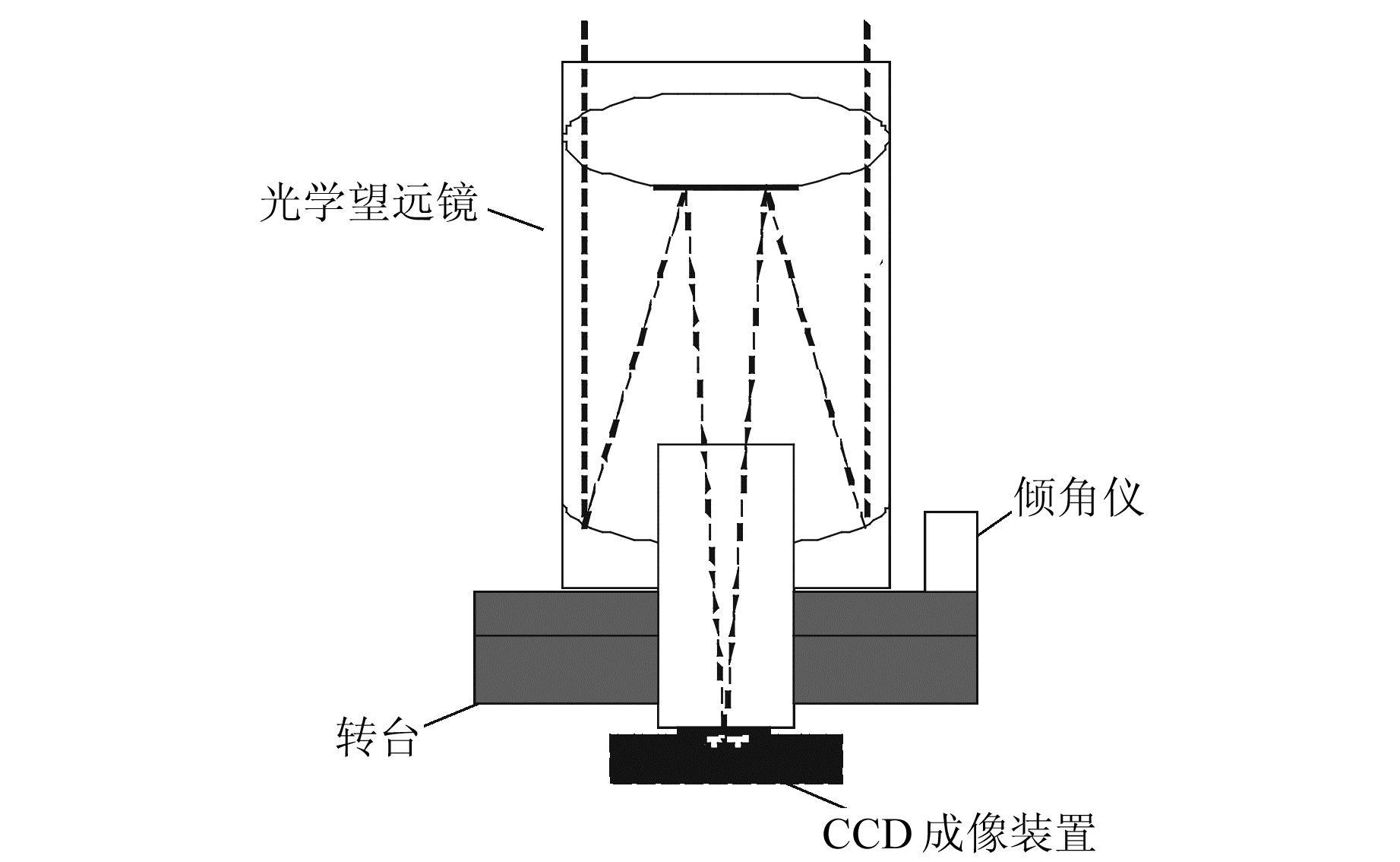
1 数字天顶仪 1.1 数字天顶仪组成如图 1所示,数字天顶仪主要由光学望远镜、CCD成像装置、精密倾角传感器(精密倾角仪)、旋转平台(转台)等组成。CCD成像装置安装于天文望远镜的成像面端,其图像敏感面重合于望远镜焦平面;精密倾角仪安装在天文望远镜的法兰盘(也可安装在旋转平台)上,与CCD成像装置、望远镜一起构成数字天顶仪主机;主机通过锁紧机构安装在旋转平台上,随转台转动。
|
图 1 数字天顶仪结构 Fig. 1 Schematic structure of digital zenith camera |
数字天顶仪通过旋转一定的角度,依次在仪器转台上各位置完成对天顶恒星的拍摄以及仪器倾斜数据的采集,全部观测过程自动实现。
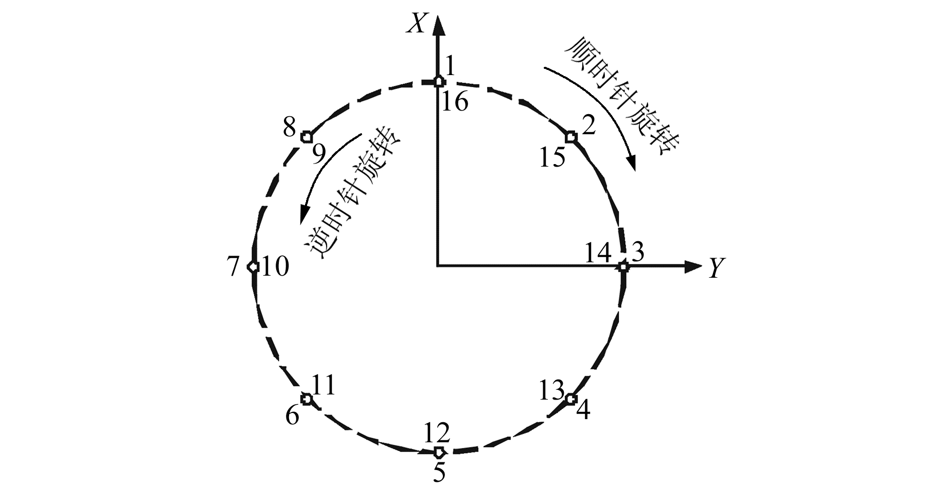
如图 2所示,数字天顶仪首先在转台的初始位置(即位置1)对测站天顶恒星进行拍摄,同时采集倾角仪敏感轴读数;位置1观测完成后,转台顺时针旋转45°,完成位置2的恒星拍摄和数据采集;之后依次顺时针旋转45°,完成位置3~8的拍摄和数据采集。在位置8上再次进行恒星拍摄和倾角仪数据采集,记为整个循环观测的位置9。然后转台依次逆时针旋转45°,分别完成位置10~16的天顶恒星拍摄和信息采集。
|
图 2 数字天顶仪观测程序 Fig. 2 Digital zenith camera observation program |
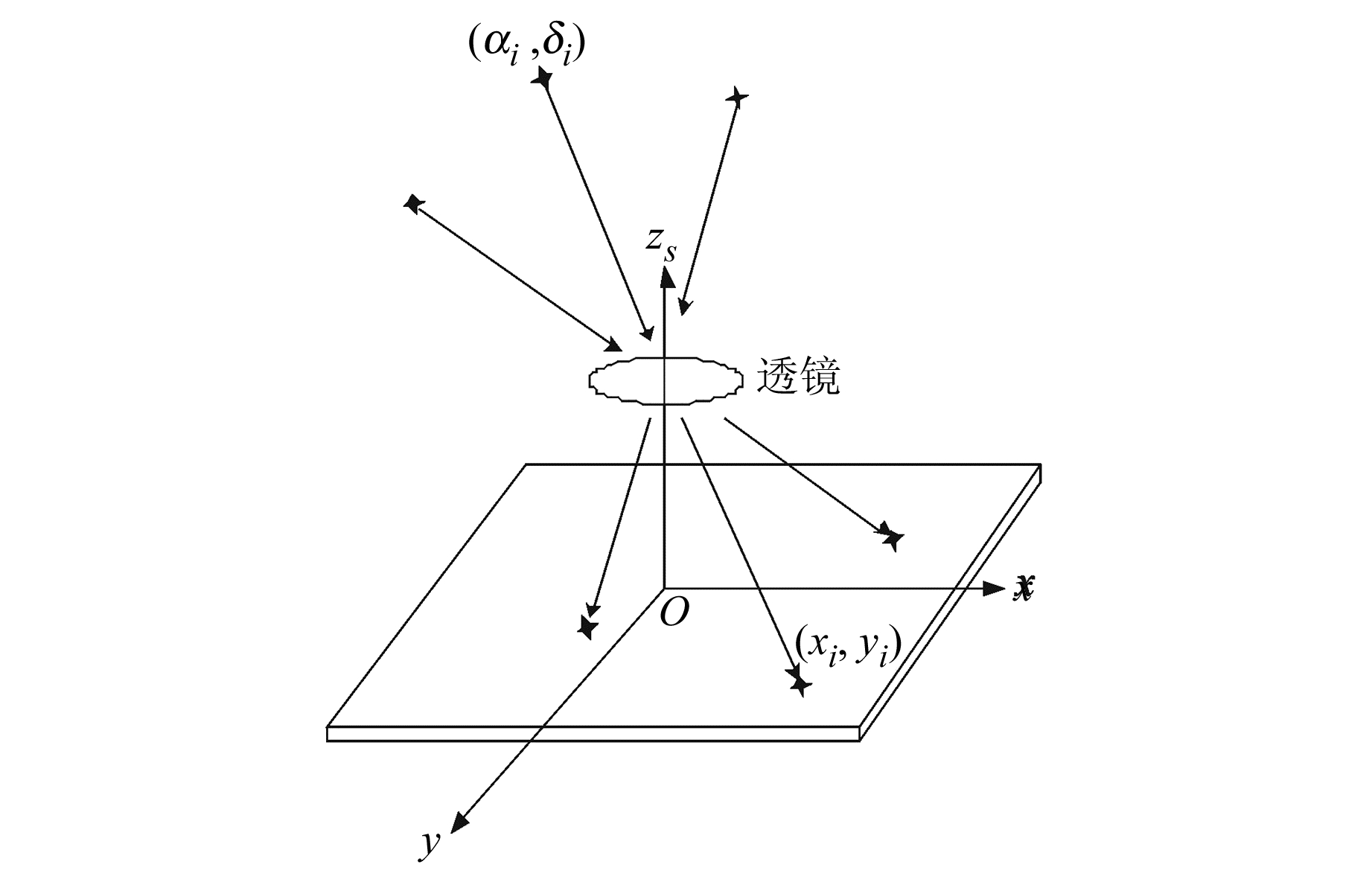
数字天顶仪成像如图 3所示,天球上某颗恒星i的天球赤道坐标为(αi, δi)。由于恒星距离地球非常遥远,星光可视为平行光,星光经过天顶仪望远镜成像于CCD面阵,像点的中心位置坐标为(xi, yi)。Oxy为建立在CCD图像传感器成像平面的CCD图像坐标系,原点位于CCD图像传感器平面中心,x、y轴方向分别平行于CCD图像传感器的两边,Ozs为天顶仪光轴指向。
|
图 3 数字天顶仪成像模型 Fig. 3 Digital zenith camera imaging model |
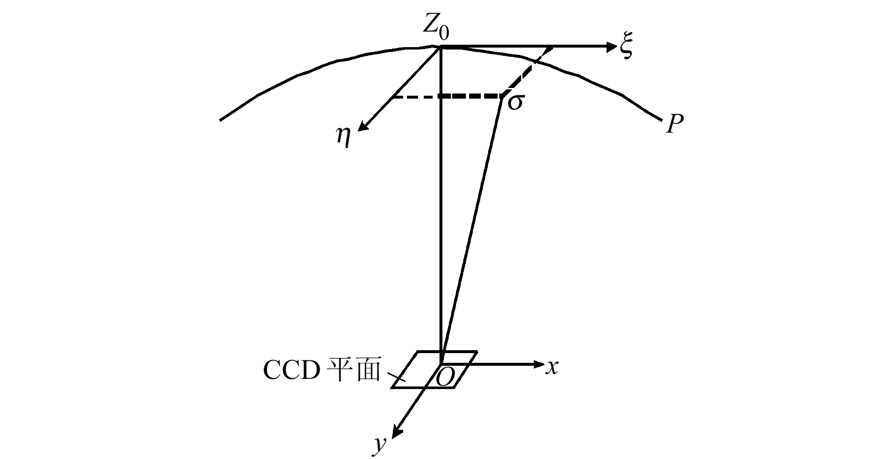
为了实现数字天顶仪的定向工作,这里采用寻找天顶仪某一已知仪器方向与真北之间夹角的方法,通过精确测定二者之间的方向角来确定北向,为此我们建立切平面坐标系。如图 4所示,切平面坐标系是以数字天顶仪旋转轴方向(或测站点概略天文经纬度确定的铅垂线方向)与天球的交点Z0为原点、子午圈切线方向为ξ轴(指向北极点)、卯酉圈切线方向为η轴(指向东)构成的平面直角坐标系。
|
图 4 切平面坐标系 Fig. 4 Tangent plane coordinate system |
切平面坐标系的ξ轴指向为北向,数字天顶仪CCD图像传感器的方位可以通过仪器上的棱镜得到。由于CCD图像坐标系的x和y轴平行于CCD图像传感器的两边,所以CCD坐标系x轴的方向是已知的,但是二者之间的夹角不能直接得到。为确定x轴与ξ轴的夹角,这里先计算倾角仪敏感轴X与北向之间的夹角。
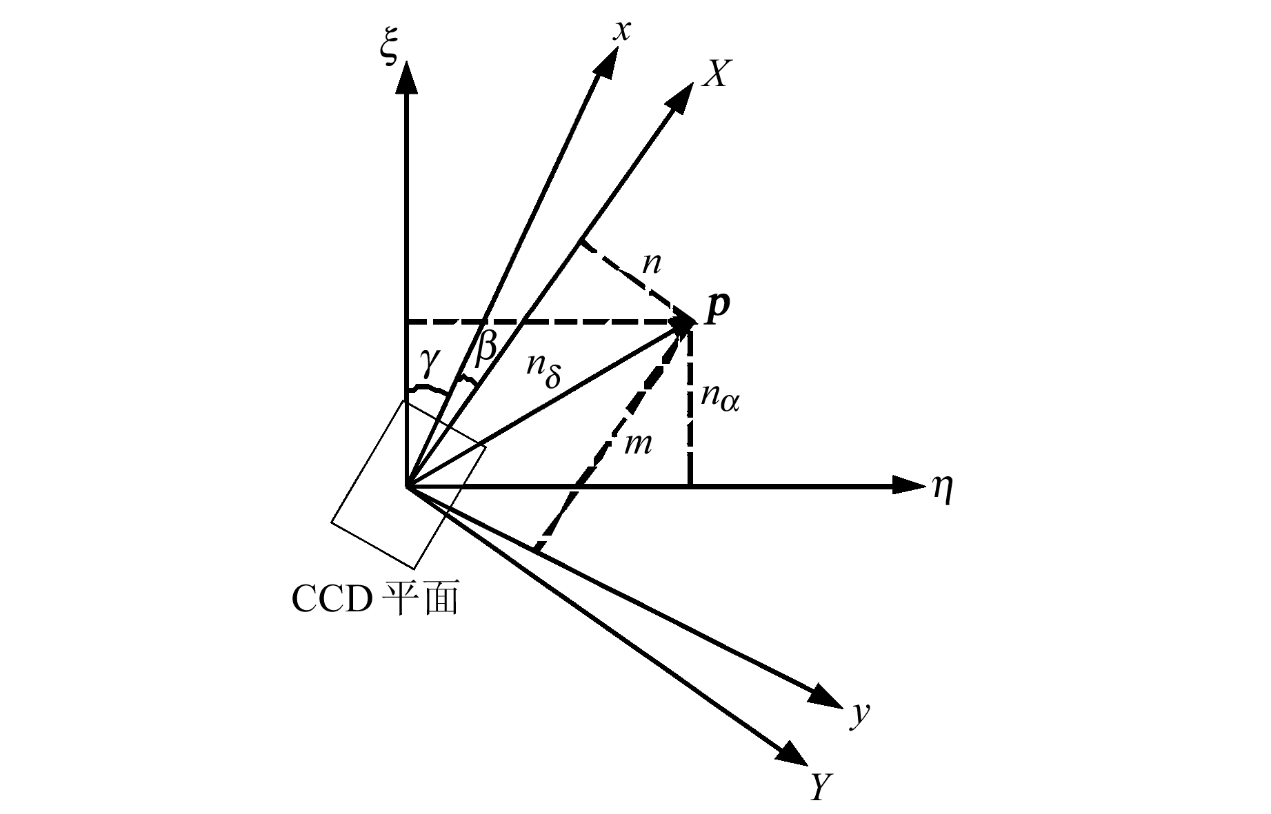
如图 5所示,X、Y为天顶仪上倾角仪的敏感轴方向,γ为CCD坐标系x轴的方位角。由于仪器在安装过程中不可避免地存在误差,倾角仪的敏感轴方向与CCD芯片边的方向并不一致,存在一定的安装误差夹角β,因此定义β为倾角仪的定向角(倾角仪X敏感轴与CCD图像坐标系x轴的夹角),γ+β为倾角仪X敏感轴的方位角。
|
图 5 数字天顶仪倾角关系示意图 Fig. 5 Tilt angle of digital zenith camera |
数字天顶仪在定向测量中,首先将仪器架设在天文坐标已知的测站点,利用长水准器进行粗调平,使气泡处于水准仪的中央位置附近,不超过水准器(格值为20″)的1/2格,然后使用倾角仪进行精调平,拍摄星图。精调平后,CCD平面仍存在微小的倾斜,倾角仪沿敏感轴方向将倾斜量分别输出。因为仪器在出厂时经过调试,这里可以认为倾角仪所测倾斜量即为CCD平面倾斜量。
由于仪器的安装误差,数字天顶仪的旋转轴和光轴无法完全重合,因此天顶仪通过拍摄对称位置星图(旋转180°得到的两幅星图)来消除旋转轴和光轴的不重合误差。m、n为一组对称位置倾角仪X、Y方向的倾斜量,可由倾角仪在两个对称位置的读数m1、m2、n1、n2确定:
| $ m = \frac{1}{2}\left( {{m_1} - {m_2}} \right),n = \frac{1}{2}\left( {{n_1} - {n_2}} \right) $ | (1) |
由图 5可知,数字天顶仪旋转轴相应切平面坐标系(ξ, η)的倾斜分量nα、nδ为:
| $ \left\{ \begin{array}{l} {n_\delta } = m\cos \left( {\gamma + \beta } \right) - n\sin \left( {\gamma + \beta } \right)\\ {n_\alpha } = m\sin \left( {\gamma + \beta } \right) + n\cos \left( {\gamma + \beta } \right) \end{array} \right. $ | (2) |
由式(2)可解得倾角仪X轴的方位角:
| $ \gamma + \beta = \arcsin \left( {\frac{{m \cdot {n_\alpha } - n \cdot {n_\delta }}}{{{m^2} + {n^2}}}} \right) $ | (3) |
设定测站点的概略天文坐标(α′, δ′)和旋转中心的CCD图像坐标(0, 0),选择处于对称位置的两幅星图进行星图识别,将识别恒星的位置转换为切平面坐标,并建立恒星切平面坐标到星点CCD图像坐标的转换关系,得到坐标转换参数。根据转换参数,由测站点概略坐标解算出旋转中心的CCD图像坐标(x0, y0),并分别求出处于对称位置的旋转中心切平面坐标(ξ0, η0)1和(ξ0, η0)2,求平均值得到(ξ0, η0)。据此可以得到旋转轴的天文坐标(αr, δr):
| $ \left\{ \begin{array}{l} {\alpha _r} = \alpha ' + \arctan \frac{{{\xi _0}}}{{\cos \delta ' - {\eta _0}\sin \delta '}}\\ {\delta _r} = \frac{{\arctan \left( {{\eta _0} + \tan \delta '} \right)\cos \left( {{\alpha _r} - \alpha '} \right)}}{{1 + {\eta _0}\tan \delta '}} \end{array} \right. $ | (4) |
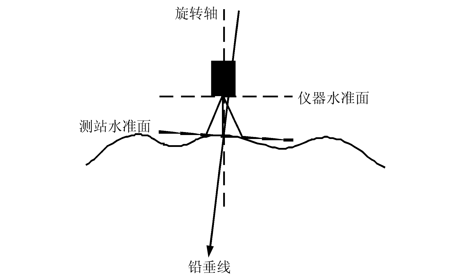
将(x0, y0)和(αr, δr)作为下一次计算的初值代入式(4)再次运算,通过数次迭代运算得到稳定的数值(αX, δX),即测站点天文坐标(数字天顶仪旋转轴天文坐标)。此天文坐标虽然经过了精调平,但是实际中无法达到CCD平面(仪器水准面)与测站水准面的完全平行,如图 6所示。
|
图 6 仪器旋转轴倾斜示意图 Fig. 6 Schematic diagram of the rotation axis of the instrument |
已知测站点天文坐标(α0, δ0),则:
| $ {\delta _n} = {\delta _X} - {\delta _0},{\alpha _n} = {\alpha _X} - {\alpha _0} $ | (5) |
式中,δn、αn是数字天顶仪旋转轴方向相对测站铅垂方向的天文坐标倾斜量。
由切平面坐标系的定义可以得到:
| $ {n_\delta } = {\delta _n},{n_\alpha } = {\alpha _n}\cos {\delta _0} $ | (6) |
式中,δ0为已知的测站点天文坐标纬度。
2.4 倾角仪定向角β的计算对任一对称位置的倾角仪状态参数,有以下两个误差方程:
| $ \left\{ \begin{array}{l} {V_\delta } = {\delta _X} - {\delta _0} + \left[ {m\cos \left( {\gamma + \beta } \right) - } \right.\\ \;\;\left. {n\sin \left( {\gamma + \beta } \right)} \right]\\ {V_\alpha } = {\alpha _X} - {\alpha _0} + \left[ {m\sin \left( {\gamma + \beta } \right) + } \right.\\ \;\;\left. {n\cos \left( {\gamma + \beta } \right)} \right]\sec {\delta _0} \end{array} \right. $ | (7) |
设倾角仪的定位角初始值为β0,修正值为Δβ,则式(7)变为:
| $ \left\{ \begin{array}{l} {V_\delta } = {\delta _X} - {\delta _0} + \left[ {m\cos \left( {\gamma + {\beta _0} + \Delta \beta } \right) - } \right.\\ \;\;\left. {n\sin \left( {\gamma + {\beta _0} + \Delta \beta } \right)} \right]\\ {V_\alpha } = {\alpha _X} - {\alpha _0} + \left[ {m\sin \left( {\gamma + {\beta _0} + \Delta \beta } \right) + } \right.\\ \;\;\left. {n\cos \left( {\gamma + {\beta _0} + \Delta \beta } \right)} \right]ec \ {\delta _0} \end{array} \right. $ | (8) |
将cos (α+β0+Δβ)、sin(α+β0+Δβ)展开:
| $ \left\{ \begin{array}{l} \cos \left( {\gamma + {\beta _0} + \Delta \beta } \right) = \cos \left( {\gamma + {\beta _0}} \right) - \\ \;\;\;\;\sin \left( {\gamma + {\beta _0}} \right)\Delta \beta \\ \sin \left( {\gamma + {\beta _0} + \Delta \beta } \right) = \sin \left( {\gamma + {\beta _0}} \right) + \\ \;\;\;\;\cos \left( {\gamma + {\beta _0}} \right)\Delta \beta \end{array} \right. $ | (9) |
将式(9)代入式(8), 并令:
| $ \left\{ \begin{array}{l} {a_1} = m\cos \left( {\gamma + {\beta _0}} \right),{a_2} = n\sin \left( {\gamma + {\beta _0}} \right)\\ {b_1} = m\sin \left( {\gamma + {\beta _0}} \right),{b_2} = n\cos \left( {\gamma + {\beta _0}} \right) \end{array} \right. $ | (10) |
则式(8)为:
| $ \left\{ \begin{array}{l} {V_\delta } = - \left( {{b_1} + {b_2}} \right)\Delta \beta + {l_\delta }\\ {V_\alpha } = \left( {{a_1} - {a_2}} \right)\sec {\delta _0}\Delta \beta + {l_\alpha } \end{array} \right. $ | (11) |
其中,
| $ \left\{ \begin{array}{l} {l_\delta } = {\delta _X} - {\delta _0} + \left( {{a_1} - {a_2}} \right)\\ {l_\alpha } = {\alpha _X} - {\alpha _0} + \left( {{b_1} + {b_2}} \right)\sec {\delta _0} \end{array} \right. $ | (12) |
由式(10)、(11)组成误差方程组,用最小二乘法解得倾角仪方位角β[10-11]。
3 实验数据分析实验中使用的数字天顶仪视场角为3°×3°,焦距为600±4 mm。CCD采用KAF-16803全画幅图像传感器,分辨率4 096像素×4 096像素,像素大小9 μm,有效面积36.8 mm×36.8 mm。双轴倾角仪为徕卡Nivel210,工作温度-20~50 ℃,测量范围±410″,分辨率为0.2″。
在西安市郊区某地运用数字天顶仪进行实验。在一个循环观测过程中,拍摄了16幅恒星星图,并记录相应位置的倾角仪数据,处于对称位置的恒星数据作为一组解算单元。实验数据如表 1所示。
|
|
表 1 部分实验数据 Tab. 1 Partial experimental data |
对实验数据进行解算,得到数字天顶仪的旋转轴天文坐标(即测站点天文坐标)。与已知的测站点坐标真值作差,进一步解算出旋转轴对应的切平面坐标系倾斜分量,如表 2所示。
|
|
表 2 旋转轴在切平面坐标系的倾斜分量 Tab. 2 The axis of rotation is tilted in the tangent plane |
由旋转轴对应的切平面坐标系倾斜分量,采用倾角仪X轴方位角解算方法,得到表 3所示的X轴方位角数据,利用最小二乘法解得的倾角仪定向角β为27.049 1°,进一步得到CCD坐标系x轴的方位角γ(即CCD坐标系x轴与北向之间的夹角),如表 3所示。
|
|
表 3 倾角仪方位角与CCD坐标系方位角 Tab. 3 Angle of azimuth and CCD coordinate system azimuth |
CCD坐标系x轴的方位角γ是利用一组对称位置上的恒星数据作为一个解算单元计算得到的,第1组数据的采集位置是图 2中的位置1和位置5,与第8组数据采集的位置12和位置16相同,因此方位角γ理论上相等。其余各组与此相同。
由数字天顶仪工作原理可知,相邻的两组数据解得的CCD坐标系x轴方位角γ应相差45°。由于仪器的机械误差等因素,转台的旋转角度可能存在一定的误差,但是转台旋转误差一般较小,可以忽略不计。将解算得到的方位角γ统一归算到位置1处,如图 7所示,并计算定向精度。

|
图 7 归算后的CCD坐标系x轴方位角 Fig. 7 The x axis azimuth angle of the CCD coordinate system |
由图 7可知,在数字天顶仪的一个循环观测过程中,归算后CCD坐标系x轴方位角γ在-39.053 234°~-38.903 816°变化。计算方位角γ的标准差σ=3.06′,解算得到的方位角γ均满足3σ的要求。
4 结语计算数字天顶仪CCD坐标系x轴的方位角,通过对处于转台对称位置的星图进行求解,得到数字天顶仪旋转轴的天文坐标。与已知测站点位置真值进行运算,得到相应的切平面坐标系倾斜量。结合观测过程中采集的倾角仪数据,解算出CCD坐标系x轴方位角,实现对北向的确定。在定向实验中,利用一个观测过程得到的16组数据,组成相应的解算单元进行运算,并运用最小二乘算法得到倾角仪定向角,提高了计算精度。实验结果表明,得到的CCD坐标系x轴方位角满足3σ要求,可以实现定向的目的。
| [1] |
田立丽, 郭金运, 韩延本, 等. 我国的数字化天顶望远镜样机[J]. 科学通报, 2014, 59(12): 1 094-1 099 (Tian Lili, Guo Jinyun, Han Yanben, et al. Digital Zenith Telescope Prototype of China[J]. Chin Sci Bull, 2014, 59(12): 1 094-1 099)
(  0) 0) |
| [2] |
曾志雄, 胡晓东, 谷林, 等. 数字天顶摄影仪的图像处理[J]. 光子学报, 2004, 33(2): 248-251 (Zeng Zhixiong, Hu Xiaodong, Gu Lin, et al. The Image Processing in the Digital Zenith Camera[J]. Acta Photonica Sinica, 2004, 33(2): 248-251)
(  0) 0) |
| [3] |
宋来勇. 基于CCD/GPS垂线偏差测量理论算法研究[D]. 青岛: 山东科技大学, 2012 (Song Laiyong. Research on Theory and Algorithm for Measuring of Vertical Deflections Based on CCD and GPS[D]. Qingdao: Shandong University of Science and Technology, 2012) http://www.wanfangdata.com.cn/details/detail.do?_type=degree&id=D301996
(  0) 0) |
| [4] |
郭敏, 张红英. CCD数字摄影在天文定位测量中的运用探讨[J]. 测绘技术装备, 2005, 7(1): 28-29 (Guo Min, Zhang Hongying. The Application of CCD in the Astronomy Orientation[J]. Measurement Technology Equipment, 2005, 7(1): 28-29)
(  0) 0) |
| [5] |
Hirt C, Seeber G. Accuracy Analysis of Vertical Deflection Data Observed with the Hannover Digital Zenith Camera System TZK2-D[J]. Journal of Geodesy, 2008, 82(6): 347-356 DOI:10.1007/s00190-007-0184-7
(  0) 0) |
| [6] |
Kerem H, Rasim D, Haluk O. Digital Zenith Camera System for Astro-Geodetic Applications in Turkey[J]. Journal of Geodesy and Geoinformation, 2012, 1(2): 115-120 DOI:10.9733/jgg.131212.1
(  0) 0) |
| [7] |
王博, 田立丽, 王政, 等. 数字化天顶望远镜观测图像及数据处理[J]. 科学通报, 2014, 59(12): 1 100-1 107 (Wang Bo, Tian Lili, Wang Zheng, et al. The Image and Data Processing in Digital Zenith Camera[J]. Chin Sci Bull, 2014, 59(12): 1 100-1 107)
(  0) 0) |
| [8] |
翟广卿, 艾贵斌. 数字天顶摄影天文定位测量的工程实现[J]. 测绘科学技术学报, 2014, 31(3): 232-235 (Zhai Guangqing, Ai Guibin. Digital Zenith Camera Astronomical Positioning Measurement of Project Implementation[J]. Journal of Geomatics Science and Technology, 2014, 31(3): 232-235)
(  0) 0) |
| [9] |
张新帅, 周召发, 黄先祥. 改进的数字天顶仪定位算法[J]. 红外与激光工程, 2015, 44(4): 1 254-1 259 (Zhang Xinshuai, Zhou Zhaofa, Huang Xianxiang. Improved Positioning Method for Digital Zenith Camera[J]. Infrared and Laser Engineering, 2015, 44(4): 1 254-1 259)
(  0) 0) |
| [10] |
杨亚非. 基于星敏感器的深空探测器姿态解析算法[J]. 测试技术学报, 2009, 23(4): 350-353 (Yang Yafei. Analytic Solution for Attitude of Deep Space Explorer Based on Star Sensors[J]. Journal of Text and Measurement Technology, 2009, 23(4): 350-353)
(  0) 0) |
| [11] |
王正亮, 唐争气, 安德笼. 基于星敏感器的航天器姿态估计[J]. 现代测绘, 2009, 32(1): 17-21 (Wang Zhengliang, Tang Zhengqi, An Delong. Attitude Determination for Spacecraft Based on Star Senor[J]. Modern Surveying and Mapping, 2009, 32(1): 17-21)
(  0) 0) |
 2018, Vol. 38


