文章信息
- 孙颖迪, 陈秋荣
- SUN Ying-di, CHEN Qiu-rong
- AZ31镁合金管材挤压成型数值模拟与实验研究
- Numerical Simulation and Experiment Study on Extrusion of AZ31 Magnesium Alloy Tube
- 材料工程, 2017, 45(6): 1-7
- Journal of Materials Engineering, 2017, 45(6): 1-7.
- http://dx.doi.org/10.11868/j.issn.1001-4381.2015.000635
-
文章历史
- 收稿日期: 2015-05-19
- 修订日期: 2016-11-15
镁合金是结构材料中最轻的金属,具有密度小、生物兼容性好、比强度和比刚度高以及易于二次使用等优点,广泛应用于航空航天、汽车与通讯工业[1-5]。其中,变形镁合金因避免了铸造镁合金显著的成分偏析与力学性能偏低等缺陷而成为众多领域重要的结构材料。在镁合金塑性成型工艺中,挤压成型以其高精度、高性能及良好表面粗糙度等优势被广泛接受,空心型材则以其显著的低耗材性,同时满足产品轻量化的结构使用要求,而具有比实心型材更明显的技术经济价值。然而,空心镁型材分流模具固有的结构复杂性与对内部金属应力场流动规律研究的匮乏性使试模周期普遍偏长,试模成本偏高[6-8]。
随着计算技术的迅速发展,数值模拟逐渐应用到材料加工领域,减少了昂贵的现场试模成本,提高了工模具设计效率,在型材加工领域得到广泛应用[9-11]。据此,本工作以典型的镁合金空心管材为研究对象,通过建成的AZ31镁合金本构方程,用目前稳定性较高的基于ALE算法的有限元软件HyperXtrude (HX) 对镁合金管材的挤出过程进行模拟,研究了焊合室结构设计对挤出过程中金属流动速率以及应力应变场分布的影响,对后期复杂型材的模具设计起到一定的指导意义。
1 研究方案 1.1 模具设计方案图 1为型材截面结构与模具三维图。图 1(a)为镁合金空心管材截面形状与主要尺寸。从图 1(a)可以看到,该型材壁厚仅有1.2mm,横截面积为70.46mm2。图 1(b),(c) 分别为模具设计方案中上模与下模三维结构,其中,上模外形尺寸为Φ149mm×66.5mm,采用三扇形分流孔,下模外形尺寸为Φ149mm×57mm,分流比为46。为强化金属流动与焊合,将分流桥截面设计为水滴形。根据型材完全对称的结构特点,焊合室的结构参数是挤压模具设计的关键,需从焊合室高度、焊合室大圆角与焊合室坡度3个方面考虑,具体设计方案如表 1所示。其中,模具三维模型与数值分析模型是按照方案中的焊合室高度H为16mm、大圆角R为18mm以及坡度α为0°设计而成。

|
图 1 型材截面结构与模具三维图(a) 型材截面结构;(b) 上模;(c) 下模Fig. 1 Structure of cross-section of the profile and the 3D model of the extrusion die(a) structure of cross-section of the profile; (b) upper die; (c) bottom die |
| Design scheme | H/mm | R/mm | α/(°) |
| 1 | 12 | 10 | 0 |
| 2 | 14 | 14 | 15 |
| 3 | 16 | 18 | 30 |
| 4 | 18 | 20 |
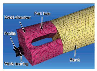
将UG中建立的模具三维模型导入HyperXtrude有限元分析软件,根据管材对称性取1/3模型进行计算,几何清理后划分网格,如图 2所示。模型分为坯料、分流孔、焊合室、工作带与出口型材5个部分,其中,工作带与型材部分网格采用三棱柱单元,其他各部分网格采用四面体单元,网格最小尺寸约为0.2mm,网格总量约90000。由于坯料部分变形较小,网格单元尺寸从工作带到坯料逐渐增大,既不影响计算精度,又可节省计算时间,提高效率。另外,AZ31镁合金材料模型采用课题组前期基于Arrhenius型方程计算得到的数理统计本构方程,如式 (1) 所示[12-14]:

|
图 2 数值分析模型Fig. 2 Mesh generation of whole numerical model |

|
(1) |
式中:
在挤压过程中,坯料在挤压筒内壁、分流孔及焊合室模面附近变形剧烈,摩擦条件设为黏着摩擦;在模具工作带部分金属获得一定的速率,变形过程的摩擦条件缓和,设定为库仑摩擦,摩擦因数为0.3。模拟中所采用的具体工艺参数 (包括坯料长度L,坯料直径d,坯料初始温度θb,模具初始温度θd,挤压筒初始温度θc与挤压速率v) 见表 2。
| L/mm | d/mm | θb/℃ | θd/℃ | θc/℃ | v/(mm·s-1) |
| 400 | 90 | 420 | 480 | 450 | 5 |
该实验前期模型分析与数值模拟在CPU为Intel (R) Core (TM) i7-4770、主频为3.4GHz、内存为16G的工作站上求解完成,确定最佳方案后在630T卧式挤压机上进行挤出实验。
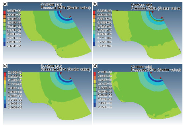
2 结果分析 2.1 焊合室高度对圆管挤压的影响焊合室高度H对管材挤压具有重要影响,分别设置H为12,14,16mm与18mm,焊合室在近工作带处的应力分布如图 3所示。表 3是对近工作带处最大压力Pmax与随机20节点压力平均值Pav的总结。从以上数据可以看出,随着焊合室高度的增大,焊合室近工作带处材料所受到的最大压力与平均压力均不断减小,不利于焊合室内金属的焊合成型,因此,焊合室高度不应取太高,一般取12~16mm即可。

|
图 3 管材挤压焊合室内近工作带处压力分布图(a)H=12mm;(b)H=14mm;(c)H=16mm;(d)H=18mm Fig. 3 Pressure distributions of the part near the work bearing of the weld chamber for the tube extrusion(a)H=12mm; (b)H=14mm; (c)H=16mm; (d)H=18mm |
| H/mm | Pmax/MPa | Pav/MPa |
| 12 | 620 | 260 |
| 14 | 610 | 256 |
| 16 | 594 | 252 |
| 18 | 574 | 223 |
在不同焊合室高度下,焊合室近工作带处金属流动速率分布图如图 4所示,其流速均值vav与均方差vSD总结于表 4中。由表 4可以看出,随着H增大,焊合室近工作带处金属流速均值逐渐增大,并在焊合室高度为16mm时达到最大值444mm/s,而后发生降低;流速均方差则表现为相反的趋势,随H增大,流速均方差先不断降低而后快速增加,并在16mm时降到最小值25.10。由于均方差能够反映流速分布的均匀性,故焊合室高度为16mm时,焊合室在近工作带截面的金属流速分布最为均匀,且此时金属流速也相对较快,有利于金属的焊合成型,故焊合室高度采用16mm较为合理。

|
图 4 管材挤压焊合室内近工作带处金属流速分布图(a)H=12mm;(b)H=14mm;(c)H=16mm;(d)H=18mm Fig. 4 Flowing velocity distributions of the part near the work bearing of the weld chamber for the tube extrusion(a)H=12mm; (b)H=14mm; (c)H=16mm; (d)H=18mm |
| H/mm | vav/(mm·s-1) | vSD/(mm·s-1) |
| 12 | 339 | 41.04 |
| 14 | 406 | 33.97 |
| 16 | 444 | 25.10 |
| 18 | 404 | 39.21 |
为消除焊合室边缘与模孔平面接合处的死区,对蝶形焊合室经常采用大圆角 (R=5~20mm)[15],如图 5(a)中标示。在本设计中,大圆角R采用10,14,18mm和20mm 4种方案。挤压过程中分流孔与焊合室部分的应力分布如图 5所示,其中,分流孔与焊合室压力最大值Pmax以及焊合室内压力均值Pav与均方差PSD总结于表 5中。可以看到,随着焊合室大圆角的增大,压力的最大值与平均值均发生降低,并在圆角为18mm时达到最小值,焊合面上近工作带处材料所受压力也呈缩减趋势,继续增加焊合室圆角,压力有所升高;同时,根据焊合室内压力均方差值的分布,大圆角取18mm时各处压力分布更均匀,有利于坯料焊合与挤出成型。

|
图 5 管材挤压分流孔焊合室部分压力分布图(a)R=10mm;(b)R=14mm;(c)R=18mm;(d)R=20mm Fig. 5 Pressure distributions of the port holes and weld chamber for the tube extrusion(a)R=10mm; (b)R=14mm; (c)R=18mm; (d)R=20mm |
| R/mm | Pmax/MPa | Pav/MPa | PSD/MPa |
| 10 | 851 | 418 | 20.04 |
| 14 | 640 | 268 | 3.67 |
| 18 | 610 | 252 | 3.61 |
| 20 | 652 | 280 | 9.11 |
将焊合室入口处做成一定角度能够改善金属的流动与焊合效果,提高焊缝质量。本设计中,设置焊合室坡度α为0°,15°,30°,其分流孔与焊合室部分应力分布如图 6所示,分流孔与焊合室的压力最大值Pmax以及焊合室内压力平均值Pav如表 6所示。可以看出,随着焊合室坡度增大,分流孔与焊合室压力最大值随之增大,从609MPa增加到657MPa,金属流动性加强,焊合室内的平均压力也不断增大,有利于材料的焊合。因此,模具的焊合室可以适当增加入口坡度。

|
图 6 管材挤压分流孔焊合室部分压力分布图(a)α=0°;(b)α=15°;(c)α=30° Fig. 6 Pressure distributions of the port holes and weld chamber for the tube extrusion(a)α=0°; (b)α=15°; (c)α=30° |
| α/(°) | Pmax/MPa | Pav/MPa |
| 0 | 610 | 253 |
| 15 | 644 | 273 |
| 30 | 657 | 291 |
焊合室入口坡度对挤压成型过程中金属流动速率也有一定影响,其中,不同入口坡度下分流孔与焊合室部分金属流动速率分布如图 7所示,焊合室内金属流动速率分布情况总结于表 7中。从图 7与表 7中可以看出,改变焊合室入口坡度对分流孔与焊合室部分的金属流动速率影响较小,但从焊合室内的速率均方差可以看出,改变焊合室入口坡度对金属流速均匀性会有一定影响,较小的入口坡度能够改善焊合室内金属流动均匀性,有利于挤压成型。因此,综合考虑焊合室压力与金属流速,焊合室入口坡度取15°较合理。

|
图 7 管材挤压分流孔焊合室部分金属流动速率分布图 (a)α=0°;(b)α=15°;(c)α=30°Fig. 7 Flowing velocity distributions of the port holes and weld chamber for the tube extrusion (a)α=0°; (b)α=15°; (c)α=30° |
| α/(°) | vav/(mm·s-1) | vSD/(mm·s-1) |
| 0 | 397 | 38 |
| 15 | 401 | 40 |
| 30 | 404 | 44 |
金属流速不均会导致挤压管材质量差、力学性能偏低等。根据对焊合室高度、大圆角以及入口坡度的优化设计,确定各参数分别为H=16mm,R=18mm,α=15°,对该优化结构下型材挤出过程金属流动性分析可依据工作带处的金属流速分布。图 8为上述优化结构中工作带部分金属流动速率分布图,可以看到,心部金属流速最快,最高达到464.3mm/s,远大于管材内外表面的金属流动速率,而在金属流动方向上速率分布比较均衡。

|
图 8 管材工作带金属流动速率分布图Fig. 8 Metal flowing velocity distribution of the work bearing for the tube |
采用优化结构参数加工模具并开模,在630t卧式挤压机上挤压型材,模具实物与型材照片如图 9(a),(b)所示,型材表面质量较好,硬度、强度等指标经质检均合格,表明数值模拟结果为实际模具设计与型材生产提供了可靠参考。同时,从图 9(c)管材挤压态组织可以看出,AZ31镁合金晶粒组织经挤压变形已明显细化,并伴有少量孪晶组织。

|
图 9 挤压模具图 (a),型材 (b) 与其金相组织 (c)Fig. 9 Pictures of extrusion die (a), profile (b) and metallurgical structure (c) |
(1) 随焊合室高度增加,焊合室内近工作带处压力不断减小,在焊合室高度为16mm时金属流速均方差达到最小值,金属流动最为均匀,综合考虑焊合效果与流速均匀,焊合室高度取16mm。
(2) 随焊合室大圆角增大,分流孔与焊合室压力的最大值与平均值均发生降低,根据焊合室内压力均方差分布,大圆角取18mm时各处压力分布更均匀,有利于坯料焊合与挤出成型。
(3) 分流孔与焊合室压力随焊合室入口坡度增大不断增大,金属流动性加强,有利于材料的焊合,但流速均方差不断降低,不利于金属流动均匀性,故入口坡度取15°较为合理。
(4) 结构优化后金属在工作带部分流速分布更为均衡,并通过实验验证生产出合格的产品,组织均匀细化,说明基于HyperXtrude有限元分析能够为实际模具设计与AZ31镁合金型材生产提供可靠参考。
| [1] | 陈振华. 变形镁合金[M].北京: 化学工业出版社, 2005. CHEN Z H. Wrought magnesium alloy[M].Beijing: Chemical Industry Press, 2005. |
| [2] | AKYUZ B. Influence of Al content on machinability of AZ series Mg alloys[J]. Transactions of Nonferrous Metals Society of China, 2013, 23(8): 2243–2249. DOI: 10.1016/S1003-6326(13)62724-7 |
| [3] | 刘正, 董阳, 毛萍莉, 等. 轧制AZ31镁合金板材 (4mm) 动态压缩性能与失效行为[J]. 材料工程, 2015, 43(2): 61–66. LIU Z, DONG Y, MAO P L, et al. Dynamic compressive properties and failure behaviour of rolled AZ31 magnesium alloy sheet (4mm)[J]. Journal of Materials Engineering, 2015, 43(2): 61–66. DOI: 10.11868/j.issn.1001-4381.2015.02.010 |
| [4] | 刘守法, 周兆锋, 李春风. 热输入对AZ31镁合金FSP试样力学性能的影响[J]. 航空材料学报, 2015, 35(1): 39–44. LIU S F, ZHOU Z F, LI C F. Effects of heat input on mechanical properties of AZ31 Mg alloy fabricated by FSP[J]. Journal of Aeronautical Materials, 2015, 35(1): 39–44. DOI: 10.11868/j.issn.1005-5053.2015.1.007 |
| [5] | HERRERA-SOLAZ V, LIORCA J, DOGAN E, et al. An inverse optimization strategy to determine single crystal mechanical behavior from polycrystal tests:application to AZ31 Mg alloy[J]. International Journal of Plasticity, 2014, 57: 1–15. DOI: 10.1016/j.ijplas.2014.02.001 |
| [6] | CHEN H, ZHAO G Q, ZHANG C S, et al. Numerical simulation of extrusion process and die structure optimization for a complex aluminum multicavity wallboard of high-speed train[J]. Materials and Manufacturing Processes, 2011, 26(12): 1530–1538. DOI: 10.1080/10426914.2011.551950 |
| [7] | ZHANG C S, ZHAO G Q, CHEN Z R, et al. Effect of extrusion stem speed on extrusion process for a hollow aluminum profile[J]. Materials Science and Engineering B, 2012, 177(19): 1691–1697. DOI: 10.1016/j.mseb.2011.09.041 |
| [8] | KUMAR S, VIJAY P. Die design and experiments for shaped extrusion under cold and hot condition[J]. Journal of Materials Processing Technology, 2007, 190(1-3): 375–381. DOI: 10.1016/j.jmatprotec.2007.01.033 |
| [9] | GUAN Y J, ZHANG C S, ZHAO G Q, et al. Design of a multihole porthole die for aluminum tube extrusion[J]. Materials and Manufacturing Processes, 2012, 27(2): 147–153. DOI: 10.1080/10426914.2011.564252 |
| [10] | ZHANG C S, ZHAO G Q, CHEN H, et al. Numerical simulation and metal flow analysis of hot extrusion process for a complex hollow aluminum profile[J]. International Journal of Advanced Manufacturing Technology, 2012, 60(1-4): 101–110. DOI: 10.1007/s00170-011-3609-7 |
| [11] | SUN Y D, CHEN Q R, SUN W J. Numerical simulation of extrusion process and die structure optimization for a complex magnesium doorframe[J]. The International Journal of Advanced Manufacturing Technology, 2015, 80(1): 495–506. |
| [12] | 孙颖迪, 李光振, 陈秋荣. AZ31镁合金方管挤压成型的数值模拟[J]. 机械工程材料, 2015, 39(10): 84–89. SUN Y D, LI G Z, CHEN Q R. Numerical simulation of square tube extrusion for AZ31 magnesium alloys[J]. Materials for Mechanical Engineering, 2015, 39(10): 84–89. DOI: 10.11973/jxgccl201510019 |
| [13] | 李光振, 孙颖迪, 陈秋荣, 等. 基于HyperXtrude的镁型材挤压数值模拟与模具优化研究[J]. 热加工工艺, 2014, 43(13): 118–123. LI G Z, SUN Y D, CHEN Q R, et al. Numerical simulation and die optimization of magnesium profile extrusion based on HyperXtrude[J]. Hot Working Technology, 2014, 43(13): 118–123. |
| [14] | 孙文君, 孙颖迪, 沈钰, 等. AZ31镁合金薄壁空心型材挤压过程数值模拟与模具优化[J]. 轻合金加工技术, 2014, 42(10): 40–45. SUN W J, SUN Y D, SHEN Y, et al. Numerical simulation of extrusion process and optimization of the die structure for a hollow AZ31 magnesium alloy profile with the thin wall[J]. Light Alloy Fabrication Technology, 2014, 42(10): 40–45. |
| [15] | 刘静安. 轻合金挤压工模具手册[M].北京: 冶金工业出版社, 2012. LIU J A. Handbook of light alloy extrusion die[M].Beijing: Metallurgical Industry Press, 2012. |
 2017, Vol. 45


