


2. 北京航空航天大学 宇航学院, 北京 10008;
3. 北京航空航天大学 生物医学工程高精尖创新中心, 北京 100083;
4. 北京科技大学 机械工程学院, 北京 100083
2. School of Astronautics, Beijing University of Aeronautics and Astronautics, Beijing 10008;
3. Beijing Advanced Innovation Center for Biomedical Engineering, Beijing University of Aeronautics and Astronautics, Beijing 100083, China;
4. School of Mechanical Engineering, University of Science and Technology Beijing, Beijing 100083, China
电磁定位系统(Electromagnetic tracking system, EM)是利用电磁感应原理测量位姿的空间定位装置,由磁场发生器、信号接收器和数据处理模块组成。EM具有精度高、反应灵活、操作简便、价格便宜以及无遮挡效应等优点,被广泛应用于医学领域手术器械的跟踪定位[1-4]。将EM与计算机断层扫描(Computed Tomography, CT)图像、X-ray图像、超声图像以及光学图像等结合可以对穿刺手术中穿刺器械的跟踪定位[5-6]以及血管介入手术中对介入器械的实时追踪[7-11]等。
铁磁性物质会对EM的工作磁场产生干扰,造成对医疗器械的定位误差,因此在不同的使用环境下,必须对EM的误差进行定量分析并对EM进行标定[12-15]。为了提高三维电磁导航系统的定位精度,Boutaleb等设计出一种60 mm×60 mm×15 mm的可移动标定块,对穿刺手术中的穿刺针的位置和姿态误差进行定量分析,进而提高EM对穿刺针的定位精度[16]。Kwartowitz等设计出一种用于测量定位系统空间定位误差的平面模型,并用该模型测量了电磁跟踪系统的定位精度[17]。Gergel等将一个三脚架并行机械臂作为标定机器人,将EM的传感器固定在机械臂末端并设计程序同时自动采集机械臂及EM测量的位姿,通过比较二者的差异来测定EM的定位精度[18]。Atuegwu和Galloway基于乐高和布孔均匀的亚克力板设计的定位精度测量模型,通过点的空间几何位置和放置于该点的EM传感器的测量值计算基准定位误差(Fiducial Localization Error, FLE), 通过FLE来衡量EM的定位精度[19]。
虽然上述学者采用多种不同的方法对EM的误差进行测量,并对EM进行标定。但是到目前为止还没有一种行之有效的、可用于临床的校正方法对EM在手术过程中受干扰后的位姿进行实时校正。基于此,本文提出一种基于薄板样条函数(Thin Plate Spline, TPS)的EM位姿校正方法,通过同时测量磁场空间16个点受干扰前后的位姿,对EM整个工作空间内测量点的位姿误差进行校正,并通过多组实验对本文提出的方法进行验证。
1 理论分析 1.1 干扰情况EM在无干扰时,其定位原理如下:磁场发生器在特定区域产生已知磁场,电磁传感器进入磁场区域后,会影响其位置周围的磁场分布产生电信号,数据处理模块根据信号接收器传回的信号进行计算得出传感器的位置信息(x, y, z)和姿态信息(α, β, γ)。
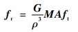
设发射矩阵为ft,磁场中位置以球坐标(ρ, φ, ψ)表示的传感器获得的接收矩阵为fr,则由接收矩阵到发射矩阵的变换满足:
|
(1) |
式中:G为系统增益;ρ为接收矩阵到发射矩阵的定位距离;A为位置变换矩阵; M为姿态变换矩阵。通过M和A即可通过传感器内置函数计算该点的位置(x, y, z)及姿态(α, β, γ)。
当受到金属物质干扰时,磁场发生器发射的磁场在金属材料内产生涡流,激发二次磁场,使得磁场产生畸变,从而使计算得到的位置变换矩阵A和姿态变换矩阵M发生变化,最终导致测得位姿参数(x, y, z)和(α, β, γ)出现误差。在临床使用中,手术室中存在铁磁性的手术刀等会对EM定位产生干扰的手术器械,因此本文需要对EM受干扰后的位姿进行校正。基于此,笔者提出1.2节的校正模型,对EM受干扰后测得的位姿进行校正。NDI Aurora电磁跟踪系统组成,如图 1所示。

|
| 图 1 NDI Aurora电磁跟踪系统组成 Fig. 1 Composition of NDI Aurora electromagnetic tracking system |
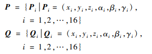
能够在不影响实际手术环境的情况下选取尽可能的少的采样点才能减少EM对手术环境的干扰,满足临床使用要求。同时,控制点的选取还受到EM工作空间大小的影响,控制点的分布要与EM实际工作空间大小相当。本文通过在EM工作空间中选取16个点,其中8个点分布在磁场发射器近端,另外8个分布在磁场发生器远端。通过分析16个点受干扰前后位姿的变化来拟合整个EM空间受干扰后的位姿变化函数。控制点受干扰前后的位姿分别记为P和Q:
|
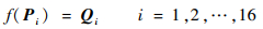
根据2个点集中控制点的特定对应性,在d维空间中找到一个合适的变形函数f,使得罚函数J最小,同时满足插值条件:
|
(2) |
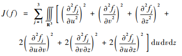
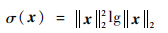
罚函数用来描述变形的平滑度和不规则性,为了保证高阶平滑,罚函数一般都包括高阶导数。在三维空间中,薄板样条函数的罚函数可以表示为式(3)所示。
|
(3) |
为使得罚函数值最小,即薄板样条函数具有最好的光滑性和规则性时,TPS插值函数可以描述为[20]
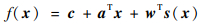
|
(4) |

|
(5) |
|
(6) |
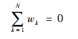
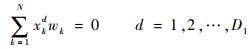
式中:D1为自变量x的维度;D2为函数值的维度;下标N为控制点个数;c∈RD2×1;a∈RD1×D2;w∈RN×D1。在插值条件式(2)以及边界条件:
|
(7) |
|
(8) |
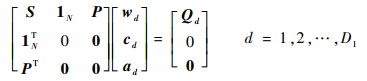
的约束下,可以将上述问题转化为矩阵的形式求解:
|
(9) |
式中:S为N×N的方阵,Sij=σ(xi-xj);1N表示值全为1的N维列向量。通过求解w、c和a,求得EM工作空间内的点受干扰前后位姿变化规律,从而对工作空间内所有点受干扰后的位姿进行校正。
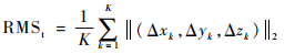
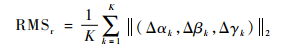
1.2.3 校正结果分析校正结果定量的用检测点校正前后的位姿参数的平均变化量以及均方根误差(Root Mean Square error, RMS)来衡量。
|
(10) |
|
(11) |
式中:K为检测点个数;RMSt和RMSr分别为位置及姿态平均误差。
2 实验验证 2.1 模型设计如图 1所示,试验用磁场发生器为NDI Aurora方盒型磁场发生器,接收器为直径为25 mm的圆盘形六自由度(x, y, z, α, β, γ)定位线圈。磁场接收器与带有定位销的放置架固定,保证实验过程中接收器重复测量同一的位置的位姿不会发生变化。
设计实验用校正模型如图 2及图 3所示,其中亚克力板上红框内均布10×10共100个定位孔,用以固定与磁场接收器固连的磁场接收器放置架。

|
| 图 2 同一平面不同干扰位置实验设计 Fig. 2 Experimental design of interference in different positions on the same plane |

|
| 图 3 同一干扰位置空间校正实验设计 Fig. 3 Experimental design of correction in space for the same interference position |
固定一块带有定位孔的亚克力板,将干扰源(手术刀柄)固定到4个不同的位置(A, B, C, D),实验中为保证干扰的随机性,A, B, C, D以及待测点位置相对于磁场发生器均不对称,如图 2所示。在每个干扰位置测量10行10列共100个点(如图 2红框所示)受干扰前后的位置及姿态误差,并通过TPS函数对干扰前后的误差进行校正。校正后各参数相对于校正前的平均位姿误差用(Δx, Δy, Δz, Δα, Δβ, Δγ)来表示。绘制受干扰后位置误差Δr及姿态误差Δw如图 4所示,图中水平面的2个坐标轴上的1~10用来对应图 2中100个点的位置,Δr= 

|
| 图 4 同一平面不同干扰位置校正前后位置及姿态误差对比 Fig. 4 Comparison of position and posture errors before and after correction of different interference positions on the same plane |
从测量的100个点中选取距离磁场发生器最近及最远各8个点,用以计算TPS函数;剩余的82个点作为检测点,用求得的TPS函数对其受干扰后的位姿进行校正,并从中选取受干扰最大区域内的20个点计算校正前后的位姿的变化及RMS,用以衡量校正结果的优劣,计算结果如表 1所示。
| 干扰位置 | Δx/mm | Δy/mm | Δz/mm | Δα/(°) | Δβ/(°) | Δγ/(°) | RMSt/mm | RMSr/(°) |
| A(校正前) | 2.210 | 1.906 | 6.414 | 5.977 | 1.739 | 4.752 | 7.533 | 8.147 |
| A(校正后) | 0.715 | 0.841 | 0.604 | 0.872 | 0.862 | 0.838 | 1.447 | 1.642 |
| B(校正前) | 7.730 | 4.542 | 3.215 | 3.826 | 3.158 | 2.154 | 9.913 | 5.873 |
| B(校正后) | 0.697 | 0.995 | 0.909 | 0.845 | 1.615 | 0.889 | 1.665 | 2.136 |
| C(校正前) | 0.697 | 1.824 | 1.560 | 2.191 | 2.538 | 1.690 | 2.661 | 4.010 |
| C(校正后) | 0.383 | 1.209 | 0.765 | 1.722 | 1.019 | 0.755 | 1.708 | 2.356 |
| D(校正前) | 1.607 | 0.534 | 1.204 | 0.897 | 1.081 | 1.723 | 2.157 | 2.383 |
| D(校正后) | 0.317 | 0.177 | 0.420 | 0.368 | 0.564 | 0.445 | 0.604 | 0.901 |
2.2.2 同一干扰位置空间校正结果
为了验证本文提出的校正方法在空间中的校正效果,将干扰源固定到图 2中的B位置,按照图 3中的方式调节支柱的高度,在0、30和120 mm的3个高度位置测量与图 2中红框位置相对应的100个点受干扰前后位姿的变化。并从测量的300个点中选取距离磁场发生器最近及最远各8个点,用以计算TPS函数,剩余的284个点作为检测点,统计284个点校正前后位置误差Δr以及姿态误差Δw的分布情况,如图 5所示。并从中选取受干扰最大区域内的20个连续的点计算校正前后的位姿的变化及RMS,用以衡量校正结果的优劣,校正结果如表 2所示。

|
| 图 5 同一干扰位置空间校正前后位姿误差分布统计 Fig. 5 Statistics of position and posture error distribution before and after correction in space for the same interference position |
| 校正前后 | Δx/mm | Δy/mm | Δz/mm | Δα/(°) | Δβ/(°) | Δγ/(°) | RMSt/mm | RMSr/(°) |
| 校正前 | 7.910 | 3.046 | 3.328 | 3.074 | 2.932 | 2.398 | 9.602 | 5.577 |
| 校正后 | 1.024 | 0.772 | 1.331 | 1.889 | 1.182 | 1.782 | 2.184 | 3.042 |
3 实验结果分析
同一平面不同干扰位置的实验结果可知干扰源距离磁场发射器越近,对测量结果的干扰越大;干扰源处于靠近工作空间中心位置比处于边缘位置对测量结果的影响更为显著。同时由图 4以及表 1可知,当磁场受干扰后,本文提出的方法可以得到较高的校正精度,校正后的位置误差可以控制在2 mm以内,姿态误差可以控制在2°以内。
同一干扰下,用本文提出的方法对受干扰后整个工作空间内的300个点进行校正,校正后的位置和姿态误差也可以控制在2 mm及2°以内。由图 5所示的校正前后位姿误差分布统计直方图可知,校正后多数检测点的位置和姿态误差大小均落在0~3范围内,校正结果显著。
4 结论本文提出一种基于少量点的EM定位系统位姿误差校正方法,并设计实验对不同干扰位置同一平面以及同一干扰位置空间内的点的位姿进行校正,均得到明显的校正结果,证明本文提出的方法对于EM定位系统的位姿校正的有效性。
| [1] |
FRANZ A M, HAIDEGGER T, BIRKFELLNER W, et al. Electromagnetic tracking in medicine:A review of technology, validation, and applications[J]. IEEE Transactions on Medical Imaging, 2014, 33(8): 1702-1725. DOI:10.1109/TMI.2014.2321777 |
| [2] |
BIRKFELLNER W, WATZINGER F, WANSCHITZ F, et al. Calibration of tracking systems in a surgical environment[J]. IEEE Transactions on Medical Imaging, 1998, 17(5): 737-742. DOI:10.1109/42.736028 |
| [3] |
PÉRIÉ D, TATE A J, CHENG P L, et al. Evaluation and calibration of an electromagnetic tracking device for biomechanical analysis of lifting tasks[J]. Journal of Biomechanics, 2002, 35(2): 293-297. DOI:10.1016/S0021-9290(01)00188-9 |
| [4] |
FEUERSTEIN M, REICHL T, VOGEL J, et al. Magneto-optical tracking of flexible laparoscopic ultrasound:Model-based online detection and correction of magnetic tracking errors[J]. IEEE Transactions on Medical Imaging, 2009, 28(6): 951-967. DOI:10.1109/TMI.2008.2008954 |
| [5] |
SHAHRIARI N, HEKMAN E, OUDKERK M, et al. Design and evaluation of a computed tomography(CT)-compatible needle insertion device using an electromagnetic tracking system and CT images[J]. International Journal of Computer Assisted Radiology & Surgery, 2015, 10(11): 1-8. |
| [6] |
HARISH V, BAKSH A, UNGI T, et al.Measurement of electromagnetic tracking error in a navigated breast surgery setup[C]//Medical Imaging 2016: Image-Guided Procedures, Robotic Interventions, and Modeling.Bellingham: International Society for Optics and Photonics, 2016: 1-8. https://www.researchgate.net/publication/301257823_Measurement_of_electromagnetic_tracking_error_in_a_navigated_breast_surgery_setup
|
| [7] |
LUND K T, TANGEN G A, MANSTAD H F. Electromagnetic navigation versus fluoroscopy in aortic endovascular procedures:A phantom study[J]. International Journal of Computer Assisted Radiology & Surgery, 2016, 12(1): 1-7. |
| [8] |
VILLAGRAN C R T, IKEDA S, FUKUDA T, et al.Catheter insertion path reconstruction with autonomous system for endovascular surgery[C]//Computational Intelligence in Robotics and Automation, 2007.Piscataway, NJ: IEEE Press, 2007: 398-403. https://www.researchgate.net/publication/4259969_Catheter_insertion_path_reconstruction_with_autonomous_system_for_endovascular_surgery
|
| [9] |
TERCERO C, IKEDA S, UCHIYAMA T, et al. Autonomous catheter insertion system using magnetic motion capture sensor for endovascular surgery[J]. The International Journal of Medical Robotics and Computer Assisted Surgery, 2007, 3(1): 52-58. DOI:10.1002/(ISSN)1478-596X |
| [10] |
FU Y L, GAO A, LIU H, et al. The master-slave catheterisation system for positioning the steerable catheter[J]. International Journal of Mechatronics and Automation, 2011, 1(3-4): 143-152. |
| [11] |
LIU H, FU Y L, ZHOU Y Y, et al. An in vitro investigation of image-guided steerable catheter navigation[J]. Proceedings of the Institution of Mechanical Engineers, Part H:Journal of Engineering in Medicine, 2010, 224(8): 945-954. DOI:10.1243/09544119JEIM730 |
| [12] |
FISCHER G S, TAYLOR R H.Electromagnetic tracker measurement error simulation and tool design[C]//International Conference on Medical Image Computing and Computer-Assisted Intervention.Berlin: Springer, 2005: 73-80. https://link.springer.com/chapter/10.1007%2F11566489_10
|
| [13] |
IKITS M, BREDERSON J D, HANSEN C D, et al.An improved calibration framework for electromagnetic tracking devices[C]//Proceedings IEEE Virtual Reality 2001.Piscataway, NJ: IEEE Press, 2001: 63-70. https://www.researchgate.net/publication/3890676_An_Improved_Calibration_Framework_for_Electromagnetic_Tracking_Devices
|
| [14] |
TRAUB J, KAUR S, KNESCHAUREK P, et al.Evaluation of electromagnetic error correction methods[C]//Bildverarbeitung Für Die Medizin 2007.Berlin: Springer, 2007: 363-367. https://link.springer.com/chapter/10.1007%2F978-3-540-71091-2_73
|
| [15] |
HIMBERG H, MOTAI Y, BRADLEY A. Interpolation volume calibration:A multisensor calibration technique for electromagnetic trackers[J]. IEEE transactions on Robotics, 2012, 28(5): 1120-1130. DOI:10.1109/TRO.2012.2198929 |
| [16] |
BOUTALEB S, RACINE E, FILLION O, et al. Performance and suitability assessment of a real-time 3D electromagnetic needle tracking system for interstitial brachytherapy[J]. Journal of Contemporary Brachytherapy, 2015, 7(4): 280-289. |
| [17] |
KWARTOWITZ D M, RETTMANN M E, HOLMES D R, et al.A novel technique for analysis of accuracy of magnetic tracking systems used in image guided surgery[C]//Medical Imaging 2010: Visualization, Image-Guided Procedures, and Modeling.International Society for Optics and Photonics.San Diego: SPIE Medical Imaging, 2010: 1-8. https://www.researchgate.net/publication/241542310_A_novel_technique_for_analysis_of_accuracy_of_magnetic_tracking_systems_used_in_image_guided_surgery
|
| [18] |
GERGEL I, GAA J, MVLLER M, et al.A novel fully automatic system for the evaluation of electromagnetic tracker[C]//Medical Imaging 2012: Image-Guided Procedures, Robotic Interventions, and Modeling.International Society for Optics and Photonics.San Diego: SPIE Medical Imaging, 2012: 1-10. https://www.researchgate.net/publication/258713829_A_novel_fully_automatic_system_for_the_evaluation_of_electromagnetic_tracker
|
| [19] |
ATUEGWU N C, GALLOWAY R L. Volumetric characterization of the Aurora magnetic tracker system for image-guided transorbital endoscopic procedures[J]. Physics in Medicine & Biology, 2008, 53(16): 4355-4368. |
| [20] |
BOOKSTEIN F L. Principal warps:Thin-plate splines and the decomposition of deformations[J]. IEEE Transactions on Pattern Analysis & Machine Intelligence, 2002, 11(6): 567-585. |