


2. 安徽埃夫特智能装备有限公司, 芜湖 241007
2. Anhui Efort Intelligent Equipment Co., Ltd, Wuhu 241007, China
工业机器人在搬运[1, 2]、码垛[3, 4]等取放作业中应用越来越广泛.在取放操作过程中,拾取物体的变化导致末端负载的改变.不同的负载和不同的控制参数(如加速度、加加速度等)相匹配[5, 6].如果相应的控制参数不变,对诸如运动精度、速度等运动性能产生不利影响,甚至可能引起机械振动[7, 8].因此需要识别机器人末端负载.
机器人负载识别一般采用力或者力矩传感器的方法获得[9, 10, 11, 12, 13, 14, 15].在静止状态下,通过测量腕部的力和力矩直接获得机器人末端负载[11, 15];或者测量机器人关节力矩通过动力学变换获得负载[11, 12].在运动状态下,利用力或力矩传感器在动力学的基础上识别机器人负载[13, 14].Atkeson等[16]在机器人动力学的基础上利用力和力矩传感器对机器人进行了动态和静态的负载识别对比.基于机器人动力学模型,采用周期激励的方法识别工业机器人有效载荷[17].虽然上述研究都能识别机器人负载,但有些方法需附加额外的力或力矩传感器测得机器人的关节力或力矩,或者需要预先识别出机器人的动态模型参数,其成本高、效率低.
本文提出了一种基于伺服电机输出力矩,无传感器的工业机器人负载识别方法.通过对机器人连杆受力分析,得到电机转矩和负载之间的关系,建立负载与电机输出的模型,实现负载识别.
1 负载识别 1.1 负载识别原理从机器人末端开始到基座,对工业机器人关节受力进行分析,获得作用在机器人每一个关节上的力和力矩,计算出平衡状态下各个关节所受的力和力矩,推导出关节力矩和末端负载之间的关系式.依据机械传动原理推导出关节力矩与电机输出转矩的关系.推导出电机的输出转矩与负载之间的数学关系式.机器人空载时和机器人带载时,分别读取机器人关节电机的输出转矩,利用差值计算出负载的质量,实现机器人末端负载的识别.机器人负载识别流程如图 1所示.
 |
| 图 1 6R型工业机器人静态识别负载的流程图Fig. 1 Flow chart of static load recognition of 6R industrial robot |
机器人的连杆为刚体,以6R机器人为例,按照D-H方法建模.连杆i及其相邻连杆之间的作用力与作用力矩的受力分析和平衡关系如图 2所示.其中i(i=1,2…,6)为杆件编号,Oi为连杆i的坐标系原点;Pi为连杆i的质心位置;Zi为坐标系Oi中z轴;Gi为在坐标系Oi中连杆i的重力矢量;fi为连杆i-1施加在连杆i上的力矢量;Mi为在坐标系Oi中连杆i-1施加在连杆i上的力矩矢量;Oi+1为连杆i+1的坐标系原点;Zi+1为 坐标系Oi+1中z轴;fi+1为在坐标系Oi+1中连杆i施加在连杆i+1上的作用力矢量;Mi+1为在坐标系Oi+1中连杆i施加在连杆i+1上的力矩矢量.
 |
| 图 2 机器人单连杆的静力和静力矩平衡关系Fig. 2 Balance relationship between static and static torque of robots single link rod |
当连杆i处于平衡状态时,连杆i所受的合力和合力矩为0,其力平衡方程为
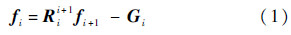
式中:Rii+1为坐标系Oi+1在坐标系Oi中的姿态变换矩阵.
力矩平衡方程为
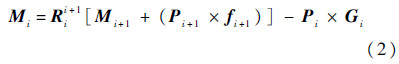
式中:Pi+1为连杆i+1的质心位置.
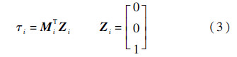
如果不考虑关节的摩擦,关节力和力矩除了驱动关节轴旋转的力矩分量外,其他分量用于保持机器人的本身机构的平衡.在连杆平衡状态下,关节i处的驱动力矩应该等于施加在连杆i上的力矩矢量和z轴单位矢量的点积,设τi为保持连杆i系统的静平衡所需的关节力矩,则有
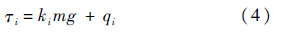
式中:ki为关节驱动力矩τi中与机器人的末端所作用的负载mg有关项的系数项,是末端相对于连杆坐标系i的x轴的位置分量,可以通过位姿矩阵求解得到;qi为τi中与负载mg无关、与连杆mig有关项之和.
当工业机器人在某一位姿下空载时,根据式(4)可以得到机器人空载时关节i的驱动力矩τik为

末端负载mg时,所处的位姿与空载时所处位姿相同的情况下,根据式(4)可得到机器人关节i的驱动力矩为

根据式(5)和式(6)可得关节i的驱动力矩在末端带载mg与空载时的差为

末端负载的质量m由式(7)可得
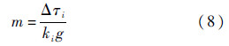
从式(8)可以看出,机器人末端负载的质量m与连杆的质量、质心等惯性参数无关.
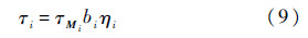
机器人的关节由伺服电机驱动,设关节i处的电机输出转矩为τMi,电机的减速比为bi,传动效率为ηi,则关节i处的驱动力矩τi与伺服电机输出转矩τMi的关系为
因此机器人的末端负载的质量为
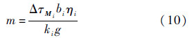
式(10)是末端负载的计算表达式.伺服电机的输出力矩直接从伺服驱动中读取,差值ΔτMi无需附加额外的传感器即可得到;减速比bi与传动效率ηi均为已知,可根据设备的型号获得.
2 试 验为了验证机器人负载识别算法,使用埃夫特机器人QH165进行试验,QH165机器人的最大负载是165 kg,关节采用松下的A5系列伺服.QH165的模型如图 3所示,D-H参数如表 1所示.
 |
| 图 3 QH165机器人模型Fig. 3 QH165 robot model |
| i | αi-1/(°) | ai-1/mm | d/mm | θi/(°) |
| 1 | 0 | 0 | 0 | 0 |
| 2 | -90 | a1(400) | 0 | -90 |
| 3 | 0 | a2(1 100) | 0 | 0 |
| 4 | -90 | a3(230) | d4(1 134.56) | 0 |
| 5 | 90 | 0 | 0 | 0 |
| 6 | -90 | 0 | d5(244) | 0 |
试验如图 4所示.机器人末端负载21 kg和70 kg.试验步骤如下:
1) 在机器人的工作空间内随机示教10个测量点.在空载的情况下,操作机器人运行到测量点并保持静止,记录测量点处机器人各个关节轴的角度和电机输出转矩τik.
2) 在机器人末端附加已知的负载,再次操作机器人运行到测量点处并保持静止,记录测量.
3) 点处机器人各个关节的角度和电机输出转矩τiz.
4) 根据两次记录的测量数据求差值,得到关节i的输出转矩差值Δτi.将ki、Δτi、减速比bi和传动效率为ηi代入式(10),求出负载质量m.
 |
| 图 4 负载识别试验Fig. 4 Load identification experiment |
采用A5自带的测量电机转矩的软件,如图 5所示,读取负载率,乘额定转矩即可得电机输出力矩.
 |
| 图 5 测量软件Fig. 5 Measurement software |
以关节2为例,关节电机采用松下A5的MHMA50ZS1H,额定输出功率为5 kW,额定转速2 000 r/min,额定转矩为23.875 nm.传动效率为80%,减速比为210.
测量各轴的移动量和2轴空载和带载时的转矩,如表 2所示.采用两组负载数据:一般负载,载荷a为21 kg;重载,载荷b为70 kg,如表 2所示.将各个轴的移动量代入位姿变换矩阵,求得末端点相对于坐标系O2x2y2z2的x2轴的位置矢量,即系数k2,如表 2所示.
| 测量点 | 关节轴角度/(°) | 2轴的扭矩/nm | k2/m | |||||||
| 1轴 | 2轴 | 3轴 | 4轴 | 5轴 | 6轴 | 空载 | 载荷a | 载荷b | ||
| 1 | 0.761 | -121.148 | 41.945 | 0.966 | 71.267 | 151.962 | 7.74 | 8.56 | 13.79 | 0.66 |
| 2 | 0.761 | -101.926 | 15.290 | -3.351 | 68.260 | 151.967 | 4.82 | 7.11 | 27.32 | 1.87 |
| 3 | 0.760 | -86.402 | 2.368 | -6.392 | 66.143 | 151.971 | 7.02 | 7.83 | 13.22 | 0.66 |
| 4 | 0.760 | -65.483 | -12.672 | -8.701 | 64.535 | 151.973 | 5.06 | 6.88 | 18.38 | 1.48 |
| 5 | -31.383 | -88.123 | 13.952 | -8.701 | 64.535 | 151.973 | 6.64 | 7.83 | 14.68 | 0.97 |
| 6 | 13.304 | -58.548 | -5.696 | -1.693 | 54.455 | 171.933 | 4.11 | 7.37 | 27.73 | 2.66 |
| 7 | 21.048 | -52.572 | -7.670 | -1.635 | 34.055 | 171.933 | 2.87 | 6.16 | 25.07 | 2.69 |
| 8 | 24.985 | -41.338 | -32.679 | -1.635 | 39.106 | 171.938 | 0.24 | 3.82 | 30.24 | 2.92 |
| 9 | 27.400 | -34.445 | -48.024 | -1.636 | 42.206 | 171.942 | 2.39 | 1.62 | 4.49 | -0.62 |
| 10 | 29.929 | -27.228 | -64.089 | -1.636 | 45.451 | 171.945 | 5.40 | 2.91 | 27.61 | -2.03 |
由表 2的数据采用式(10)计算出负载的质量,如表 3和图 6所示.识别的负载与实际的负载相差较小.但是由于在计算的时候不考虑摩擦力和关节变形导致误差存在.负载越大摩擦力和关节变形越大,导致的误差越大.测量21 kg负载相对误差为0.002%,而70 kg负载的相对误差为 0.003 9%.
| 测量点 | 实际负载/kg | 识别负载/kg | 相对误差/% | |||
| 载荷a | 载荷b | 载荷a | 载荷b | 载荷a | 载荷b | |
| 1 | 21 | 70 | 20.99 | 68.21 | 0.047 6 | 2.551 7 |
| 2 | 21 | 70 | 21.20 | 71.79 | 0.952 4 | 2.557 1 |
| 3 | 21 | 70 | 21.09 | 71.31 | 0.428 6 | 1.871 4 |
| 4 | 21 | 70 | 20.77 | 69.14 | 1.095 2 | 1.228 6 |
| 5 | 21 | 70 | 20.68 | 68.78 | 1.523 8 | 1.742 9 |
| 6 | 21 | 70 | 21.56 | 71.55 | 2.666 7 | 2.214 3 |
| 7 | 21 | 70 | 20.87 | 68.77 | 0.619 0 | 1.757 1 |
| 8 | 21 | 70 | 20.92 | 69.38 | 0.381 0 | 0.885 7 |
| 9 | 21 | 70 | 21.00 | 69.97 | 0 | 0.042 9 |
| 10 | 21 | 70 | 21.34 | 71.37 | 1.619 0 | 1.957 1 |
| 平均值 | 21 | 70 | 21.042 | 70.027 | 0.002 0 | 0.003 9 |
 |
| 图 6 试验数据与实际数据对比分析图Fig. 6 Analysis diagram of comparison between experimental data and the actual data |
本文提出了一种机器人静态识别负载的方法:
1) 采用该方法识别负载时,利用伺服电机的输出力矩,无需额外的传感器,节约了成本,简单易行.
2) 在埃夫特机器人QH165上进行了试验验证,实际负载与测得的负载相对误差小.
3) 由于忽略了关节摩擦和关节变形,导致误差.试验结果验证了该负载识别方法的正确性及可行性.
| [1] | Ko C M, Chung G J, Kin D H.Designing of heavy duty handling robot (HEDURI-I robot design)[C]//Proceedings of the 2009 IEEE International Conference on Mechatronics.Piscataway, NJ:IEEE Press, 2009:1-6. |
| Click to display the text | |
| [2] | Feng Y L, Qu D K, Xu F, et al.Analysis and compensation for the dynamic error of the FPD glass substrates transfer robot[C]//IEEE International Conference on Robotics and Automation.Piscataway, NJ:IEEE Press, 2011:1-3. |
| Click to display the text | |
| [3] | Lu D M, Zhang C Q, Fan Y Z, et al.The kinematic self-calibration method and simulation of one palletizing robot[C]//Proceedings of the 8th World Congress on Intelligent Control and Automation.Piscataway, NJ:IEEE Press, 2010:6424-6427. |
| Click to display the text | |
| [4] | Guang X Q, Wang J D.Mechanical design and kinematic analysis of a new kind of palletizing robot[C]//Mechanic Automation and Control Engineering.Piscataway, NJ:IEEE Press, 2011:199-202. |
| Click to display the text | |
| [5] | Tsumugiwa T, Watanabe Y, Yokogawa R.Robot motion control using mechanical load adjuster with motion measurement interface for human-robot cooperation[C]//Intelligent robots and systems.Piscataway, NJ:IEEE Press, 2009:467-472. |
| Click to display the text | |
| [6] | Song Y F, Wang H G, Gao W B, et al.Dynamic deformation analysis of a spot welding robot under high speed and heavy load working condition[C]//IEEE International Conference on Robotics and Biomimetics.Piscataway, NJ:IEEE Press, 2013:2043-2048. |
| Click to display the text | |
| [7] | Seki K, Nakamura H, Iwasaki M, et al.Suppression of resonant vibration due to angular transmission errors of reduction gearing in industrial robots[C]//IEEE International Conference on Mechatronics (ICM).Piscataway, NJ:IEEE Press, 2013:835-840. |
| Click to display the text | |
| [8] | Huang L S, Qu D K, Xu F.Motion control strategy of industrial direct drive robot for vibration suppression[C]//Intelligent Control and Automation.Piscataway, NJ:IEEE Press, 2010:2430-2433. |
| Click to display the text | |
| [9] | Hamon P, Gautier M, Garrec P, et al.Dynamic identification of robot with a load-dependent joint friction model[C]//Robotics Automation and Mechatronics.Piscataway, NJ:IEEE Press, 2010:129-135. |
| Click to display the text | |
| [10] | Hamon P, Gautier M, Garrec P.Dynamic identification of robots with a dry friction model depending on load and velocity[C]//Intelligent Robots and Systems.Piscataway, NJ:IEEE Press, 2010:6187-6193. |
| Click to display the text | |
| [11] | Paul R P.Robot manipulators:Mathematics, programming, and control[M].Cambridge:MIT Press, 1981:157-195. |
| Click to display the text | |
| [12] | Coiffet P.Robot technology:Interaction with the environment[M].2nd ed.Englewood Cliffs:Prentice-Hall, 1983:102-128. |
| Click to display the text | |
| [13] | Amitabha M.Adaptation in biological sensory-motor systems:A model for robotic control[C]//Intelligent Robots and Computer Vision.Bellingham, WA:SPIE, 1984, 521:243-247. |
| Click to display the text | |
| [14] | Amitabha M, Ballard D H.Self-calibration in robot manipulators[C]//Robotics and Automation.Piscataway, NJ:IEEE Press, 1985:1050-1057. |
| Click to display the text | |
| [15] | Olsen H B, Bekey G A.Identification of parameters in models of robots with rotary joints[C]//Robotics and Automation.Piscataway, NJ:IEEE Press, 1985:1045-1050. |
| Click to display the text | |
| [16] | Atkeson C G, An C H, Hollerbach J M.Estimation of inertial parameters of manipulator loads and links[J].International Journal of Robotics Research, 1986, 5(3):101-119. |
| Click to display the text | |
| [17] | Swevers J, Verdonck W, de Schutter J.Dynamic model identification for industrial robots[J].IEEE Control Systems Magazine, 2007, 27(5):58-71. |
| Click to display the text |