


2. 中航工业第一飞机设计研究院, 西安 710089
2. The First Aircraft Design and Research Institute of China Aviation Industry, Xi'an 710089, China
近年来,纤维增强复合材料加筋结构被广泛运用到飞机结构设计中[1].加筋结构的主要破坏模式是丧失稳定性,Ovesy等人使用有限条素法对加筋结构稳定性进行了研究[2],Stamatelos等人特别研究了加筋结构的局部失稳问题[3],复合材料加筋板在局部失稳后仍具有较强承载能力,即后屈曲承载[4, 5].研究表明,充分利用复合材料加筋板后屈曲承载能力可以大幅提高结构承载效率[6].在复材加筋板的加工制造以及使用维护中难免会引入初始缺陷,研究初始缺陷对加筋板屈曲及后屈曲特性的影响已成为国内外学者关注的重点[7].Falzon和Orifici等人[8, 9]对节线与反节线上弯矩和扭矩引起的复合材料加筋板脱粘问题进行了深入研究,探讨了筋条与蒙皮间界面上的传载机理.Lanzi和Oh等人[10, 11]利用内聚力单元及虚拟裂纹闭合技术(VCCT,Virtual Crack Closure Technology)有效模拟了加筋板的脱粘过程.
某些结构类型加筋板在受到轴向压缩时,由于加筋板一阶和二阶屈曲载荷十分接近,因此失稳模态存在不确定性.而不同失稳模态对预置缺陷起始扩展及扩展过程有明显不同的影响,这将直接影响结构的后屈曲承载能力.由于试验的复杂性,目前国内外对这一问题的研究相对较少.
本文利用试验与数值模拟手段,对不同屈曲模态下预置缺陷的扩展特性进行详细研究,进而探讨不同缺陷扩展方式与复合材料加筋板后屈曲承载的关系,从而建立失稳模态与后屈曲承载能力之间的联系.为更加安全有效地设计加筋板结构提供理论指导. 1 试验对象及方法
设计一阶屈曲载荷和二阶屈曲载荷相近的复合材料加筋板,示意图如图 1所示.加筋板为典型的三加筋结构,筋条剖面为工型.中筋条中央位置与蒙皮接触处预置脱胶缺陷,缺陷在宽度方向贯穿下缘条,长度分别为30mm和50mm.试验件采用国产碳纤维CCF300制成,基体为BA9916,试验件表面铺设平纹织物,内部铺层以单向带为主,织物及单向带材料属性的测试结果详见表 1.按其成型工艺,将其分为A~E 5个区域.各区域铺层方式见表 2.试验件共6件分2组,各含30mm和50mm长度预置缺陷.
 |
| 图 1 复合材料加筋板结构示意图Fig. 1 Schematic figure of the composite stringer-stiffened |
| 属性 | E11/GPa | E22/GPa | G12/GPa | ν12 | XT/MPa | XC/MPa | YT/MPa | YC/MPa | S12/MPa |
| 织物 | 57.6 | 57.6 | 4.5 | 0.06 | 710 | 671 | 710 | 661 | 160 |
| 单向带 | 121.2 | 9.7 | 5.3 | 0.31 | 1590 | 1360 | 78.5 | 220 | 132 |
| 属性 | Knn,Ktt,Kss/(N/m) | tn0/MPa | tt0,ts0/MPa | Gnc/(kJ/m2) | Gsc,Gtc/(kJ/m2) | ||
| Cohesive界面 | 106 | 60 | 70 | 0.3 | 0.7 |
| 区域 | 铺层 |
| A | [±45°/0°2/+45°/90°/-45°/0°2/+45°/0°/-45°/0°2/-45°] |
| B,C | [0°/+45°/0°2/-45°/90°/+45°/0°2/±45°] |
| D | [0°/+45°/0°2/-45°/90°/+45°/0°2] |
| E | [±45°/0°/+45°/90°/-45°/0°/-45°/0°/+45°2/90°/-45°/0°]s |
试验中,距两端各115mm处设置支撑刀口模拟翼肋支撑及端部简支作用.使用影像干涉云纹法对试验件工作段失稳模态进行实时监测;试验中引入超声C扫技术监测预置缺陷的起扩及扩展情况.试验结果在本文第3节与数值模拟结果一起给出. 2 有限元模型 2.1 有限元模型
使用ABAQUS建立有限元模型如图 2所示,蒙皮与筋条采用连续壳单元(SC8R),共40000个;中筋条-蒙皮含缺陷界面采用虚拟裂纹闭合技术(VCCT)模拟,两侧无缺陷界面采用基于内聚力的界面单元(COH3D8),共2000个.将有限元模型两端与特征点耦合(COUPLE),一端施加固支约束,另一端仅放开加载方向自由度,同时通过位移约束模拟支撑刀口的限制作用.模型材料参数参考表 1.
 |
| 图 2 复合材料加筋板有限元模型Fig. 2 Finite element model of composite stringer-stiffened structure |
使用二维Hashin损伤判据判断试验件复合材料层内损伤的发生.Hashin准则将复合材料单向带的层内失效区分为纤维失效与基体失效,并使用单层内应力来判断其是否失效.这一准则已经成功应用到复合材料单向带层板的强度预测上.其失效准则如下:
纤维拉伸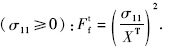
纤维压缩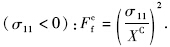
基体拉伸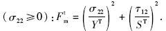
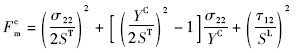
基体压缩(σ22<0):
损伤起始发生后,材料进入损伤演化阶段,材料刚度逐渐下降,直到刚度为零,损伤区域完全破坏.本文采用基于能量的线性损伤演化法则,如图 3所示.
 |
| 图 3 复合材料双线性损伤演化模型Fig. 3 Bilinear constitutive mode of composite material |
Raju等人[12]指出使用VCCT技术模拟含预置缺陷界面时,细化网格对缺陷前缘能量释放率边界有影响但对其内部无影响,且总体趋势一致.本模型中采用B-K混合模式断裂准则判断缺陷扩展.
满足:Gequ/Gequc≥1时,裂纹发生扩展.Gequ为当量应变能释放率;Gequc为临界应变能释放率;断裂韧性GⅠc,GⅡc和GⅢc参数一般由试验测得,本文参考文献[13]取值,指数η=1.45,GIc=0.4kJ/m2,GⅡc=GⅢc=1.1kJ/m2. 2.4 几何初始扰动
通常而言,任何实际结构都会不可避免存在几何缺陷.这些几何缺陷很难在计算模型中准确地反映[14].为此,模型引入了几何初始扰动,借鉴目前国内外学者的做法,分为两步:首先进行特征值线性屈曲分析,来获得失稳载荷及相应失稳模态下每个节点上的相对位移;然后将节点位移作为一种上述几何缺陷的等效替代引入非线性后屈曲模型. 3 结 果 3.1 屈曲特性
试验中当压缩载荷超过试验件的临界失稳载荷后,蒙皮随即发生局部失稳,根据云纹图像可以直观确定失稳模态及失稳载荷.含30mm缺陷的试验组中,2块加筋板表现为纵向3个半波失稳模态,1块表现为2个半波;含50mm缺陷的试验组中,2块加筋板表现为纵向2个半波,1块表现为3个半波.数值模拟也得到相似的结果:一阶与二阶失稳模态分别为纵向3个半波和2个半波,且对应的失稳载荷极为接近.图 4和图 5所示分别为纵向3个半波和纵向2个半波模态试验及模拟结果;所有试验件的试验结果及数值模拟结果如表 3所示.
 |
| 图 4 复合材料加筋板纵向3个半波模态Fig. 4 Developing process of buckling mode with three half-waves for composite stringer-stiffened panel |
 |
| 图 5 复合材料加筋板纵向2个半波模态Fig. 5 Developing process of buckling mode with two half-waves for composite stringer-stiffened panel |
| 试验件 | 屈曲模态/半波数 | 屈曲载荷/kN | 破坏载荷/kN | 承载能力最大误差/% | |||
| 试验 | 计算 | 试验 | 计算 | 试验 | 计算 | ||
| 30-1 | 3 | 3 | 410 | 406.4 | 749.8 | 729.7 | 2.7 |
| 30-2 | 2 | 2 | 420 | 406.7 | 629.9 | 613.3 | 2.6 |
| 30-3 | 3 | 420 | 695.8 | ||||
| 50-1 | 3 | 3 | 410 | 407.7 | 711.0 | 677.12 | 4.8 |
| 50-2 | 2 | 2 | 420 | 409.1 | 680.2 | 606.6 | 12 |
| 50-3 | 2 | 420 | 689.7 | ||||
在图 4及图 5中定义反节线和节线,由此可知,对于失稳模态表现为3个半波的加筋板,预置缺陷位于反节线上;而失稳模态表现为2个半波的加筋板,预置缺陷位于节线上. 3.2 后屈曲特性 3.2.1 后屈曲承载及破坏模式
加筋板蒙皮发生弯曲变形即局部失稳,蒙皮的凹凸变形使得筋条扭转,结构还将继续承载即进入后屈曲阶段.后屈曲阶段结构承载呈非线性增加,直至筋条折断,结构瞬间失去承载能力.所有试验件的试验结果与数值模拟结果见表 3.从表中分析可知,2个半波失稳模态的加筋板后屈曲承载能力明显低于3个半波失稳模态的加筋板;对于表现相同失稳模式的加筋板,预置缺陷长度对加筋板的后屈曲承载能力有明显影响,含50mm长度预置缺陷的加筋板破坏强度明显低于含30mm长度预置缺陷的加筋板.
该型试验件的破坏模式基本相同,如图 6所示.破坏后蒙皮平行于宽度方向折断,3根筋条全部折断,筋条与蒙皮之间出现大面积脱粘分离,数值模拟也得到了一致的破坏模式,如图 7所示.
 |
| 图 6 加筋板试验件典型压缩破坏模式Fig. 6 Photographs of typical failed mode of composite stringer-stiffened panel in compression |
 |
| 图 7 数值模型破坏模式(纤维损伤图)Fig. 7 Calculation result of failure modes (fiber failure) |
试验过程中使用超声C扫监测预置缺陷在后屈曲过程中的扩展情况.由于技术限制,试验采用加载-卸载-扫描的非连续式扫描方案.相关研究[15]表明复合材料加筋板结构的缺陷在临近破坏瞬间急剧扩展,因此不能准确地扫描到破坏或临近破坏瞬间的缺陷扩展情况.因此数值方法的补充是十分重要的.
试验与数值模拟均表明,含30mm缺陷与含50mm缺陷加筋板在同种失稳模态下缺陷的起扩及扩展情况相同,故本文只给出含30mm缺陷加筋板的缺陷扩展图.图 8所示为试验中使用超声C扫监测到的两种失稳模式下缺陷的扩展图,图 9所示为模型计算中观测到的缺陷扩展情况.
 |
| 图 8 加筋板试验监测缺陷扩展渐进图Fig. 8 Debond propagation process for composite stringer-stiffened panels in calculation |
 |
| 图 9 加筋板模拟计算缺陷扩展渐进图Fig. 9 Debond propagation process for composite stringer-stiffened panels in calculation |
分析图 8a与图 9a可知,对于失稳模态表现为3个半波的加筋板,缺陷在临近破坏时才出现起始扩展,这也是试验中没有监测到缺陷明显扩展的原因,缺陷扩展始于自由边一侧,向另一侧缓慢扩展,在破坏的瞬间迅速大面积扩展.结合图 8b与图 9b可知,对于失稳模式表现为2个半波的加筋板,缺陷起始扩展出现在破坏载荷的74%,相对较早,缺陷扩展始于自由边对角,后从对角处缓慢持续扩展,在结构破坏瞬间迅速大面积扩展. 4 结果分析 4.1 屈曲特性分析
对比试验结果与数值模拟可知:对该型加筋板,其一阶失稳模态表现为3个半波,二阶失稳模态表现为2个半波,一二阶失稳载荷极其接近,故轴压试验中将可能发生一阶或二阶失稳. 4.2 后屈曲特性分析
失稳模态直接决定后屈曲阶段缺陷的起扩及扩展过程,从而影响结构承载.以含30mm缺陷为例通过分析计算模型中裂纹前缘的应变能释放率来进一步探讨不同模态下缺陷的起扩及扩展过程.含50mm缺陷与此类似,在此没有给出.预置缺陷区域如图 10所示,定义上下(up-down)裂纹前缘及自由边.
 |
| 图 10 加筋板预置缺陷区域Fig. 10 Embed debond zone of stringer-stiffened panels |
对于失稳模态呈现2个半波的试验件,预置缺陷位于其节线上.图 11显示的是节线上缺陷临近起始扩展时上下裂纹前缘的应变能释放率,从图中可知缺陷在对角处能量释放率达到最大值且上下对称,以GⅡ为主驱动裂纹对角扩展.Stevens等人[16]指出节线上预置缺陷处筋条将承受最大扭矩,由此在预置缺陷的对角处产生垂直于裂纹前缘的剪应力,促使裂纹滑移(Ⅱ型)扩展.扭矩的作用使得缺陷在结构屈曲之后不久出现起始扩展,而降低了结构后屈曲承载能力.
 |
| 图 11 临近起扩时(73%破坏载荷)裂纹前缘的应变能 释放率(ENRRT)-节线(2个半波失稳模式)Fig. 11 The ENRRT of front edge on the node line closed to propagation (73% of strength) for two half-waves mode |
对于失稳模态呈现3个半波的试验件,预置缺陷位于反节线上.反节线上缺陷临近起始扩展时上下裂纹前缘的应变能释放率如图 12所示,可知缺陷两侧能量释放率不对称,能量释放率大的一侧将先出现扩展,并以GⅢ为主驱动裂纹扩展.相比节线上筋条传载,反节线上筋条受力复杂,不但承受筋条扭转,还承受蒙皮变形引起的横向弯矩影响.横向弯矩在预置缺陷的两侧产生平行于裂纹前缘的剪应力,促使裂纹撕开(Ⅲ型)扩展.裂纹临近结构破坏才发生扩展,有利于提高结构后屈曲承载能力.
 |
| 图 12 临近起扩时(97%破坏载荷)裂纹前缘的应变能 释放率(ENRRT)-反节线(3个半波失稳模式)Fig. 12 The ENRRT of front edge on the antinode line closed to propagation (97% of strength) for three half-waves mode |
1) 基于ABAQUS运用VCCT和引入几何缺陷技术建立有限元模型,可以模拟含缺陷复合材料加筋板的后屈曲过程,模拟结果与试验结果相吻合;
2) 试验和计算均表明该型加筋板3个半波失稳模态下的后屈曲承载能力强于2个半波;
3) 节线上预置缺陷扩展从自由边对角起始,出现在74%破坏载荷左右;反节线上预置缺陷扩展从一侧自由边起始,出现在临近破坏时;
4) 使用裂纹前缘应变能释放率可以有效地探讨不同模态下缺陷的扩展机理,节线上缺陷扩展以Ⅱ型(即滑移型)为主,此时筋条承受最大扭矩;反节线上筋条横向弯矩作用缺陷扩展以Ⅲ型为主.
| [1] | 杜善义,关志东.我国大型客机先进复合材料应对策略思考[J].复合材料学报,2008,25(1):1-10 Du Shanyi,Guan Zhidong.Strategic considerations for developm- ent of advanced composite technology for large commercial aircraft in China[J].Acta Materiae Composite Sinica,2008,25(1):1-10(in Chinese) |
| Cited By in Cnki (76) | |
| [2] | Ovesy H R,Ghannadpour S A M,Zia-Dehkordi E.Buckling analysis of moderately thick composite plates and plate structures using an exact finite strip[J].Composite Structures,2013,95:697-704 |
| Click to display the text | |
| [3] | Stamatelos D G,Labeas G N,Tserpes K I.Analytical calculation of local buckling and post-buckling behavior of isotropic and orthotropic stiffened panels[J].Thin-Walled Structures,2011,49(3):422-430 |
| Click to display the text | |
| [4] | Nicholls D J,Gallagher J P.Determination of GIC in angle ply composites using a cantilever beam test method[J].Journal of Reinforced Plastics and Composites,1983,2(1):2-17 |
| Click to display the text | |
| [5] | Chai H.The characterization of mode Ⅰ delamination failure in nonwoven,multidirectional laminates[J].Composites,1984,15(4):277-290 |
| Click to display the text | |
| [6] | Abramovich H,Weller T.Buckling behavior of composite laminated stiffened panelsunder combined shear and axial compression[R].AIAA-2005-1933,2005 |
| Click to display the text | |
| [7] | Xu J F,Zhao Q,Qiao P Z.A critical review on buckling and post-buckling analysis of composite structures[J].Frontiers in Aerospace Engineering,2013,2(3):157-168 |
| [8] | Falzon B G,Stevens K A,Davies G O.Postbuckling behaviour of a blade-stiffened composite panel loaded in uniaxial compression[J].Composites Part A:Applied Science and Manufacturing (Incorporating Composites and Composites Manufacturing),2000,31(5):459-468 |
| Click to display the text | |
| [9] | Orifici A C,Shah S A,Herszberg I,et al.Failure analysis in postbuckled composite T-sections[J].Compsite Structures,2008,86(1-3):146-153 |
| Click to display the text | |
| [10] | Lanzi L.A numerical and experimental investigation on composite stiffened panels into post-buckling[J].Thin-Walled Structures, 2004,42(12):1645-1664 |
| Click to display the text | |
| [11] | Oh S H,Kim K S,Kim C G.An efficient postbuckling analysis technique for composite stiffened curved panels[J].Composite Structures,2006,74(3):361-369 |
| Click to display the text | |
| [12] | Raju I S,Sistla R,Krishnamurthy T.Fracture mechanics analyses for skin-stiffener debonding[J].Engineering Fracture Mechanics,1996,54(3):371-385 |
| Click to display the text | |
| [13] | 田甜.含脱粘复合材料加筋板损伤容限研究[D].北京:北京航空航天大学,2011 Tian Tian.Damage tolerance of stiffened composite panels with debonding defects[D].Beijing:Beijing University of Aeronautics and Astronautics,2011(in Chinese) |
| [14] | Hilburger M W,Starnes J H.Effects of imperfections of the buckling response of composite shells[J].Thin-Walled Structures,2004,42(3):369-397 |
| Click to display the text | |
| [15] | Degenhardt R,Kling A,Rohwer K,et al.Design and analysis of stiffened composite panels including post-buckling and collapse[J].Computers and Structures,2008,86(9):919-929 |
| Click to display the text | |
| [16] | Stevens K A,Ricci R,Davies G A O.Buckling and postbuckling of composite structures[J].Composites,1995,26(3):189-199 |
| Click to display the text |