The article information
- Alok Kumar Das, Partha Saha
- Machining of circular micro holes by electrochemical micro-machining process
- Advances in Manufacturing, 2013, 1(4): 314–319
- http://dx.doi.org/10.1007/s40436-013-0042-1
-
Article history
- Received: 2013-12-12
- Accepted: 2014-01-14
- Published online: 2014-02-11
2. Indian Institute of Technology Kharagpur, Kharagpur, West Bengal, India
Micro-electrochemical machining (micro ECM) appears to be one of the rather promising micro-machining techniques in many application areas. It offers several advantages including higher machining rate and better precision. In addition, a wide range of materials can be machined [1]. In micro ECM, the electrochemical reaction is localized by the voltage pulses application of a few hundred nanoseconds width. Machining of micro-holes, with diameter of a few micrometers is possible to achieve by this process. In recent years, much progress has been made in the micro machining field with emphases laid on the suitability of certain particular process to produce micro features [2]. Bhattacharyya and Munda [3] developed a set up to carry out in-depth study on the influence of electrochemical process parameters, such as machining voltage, electrolyte concentration, pulse on time of pulsed power supply on the material removal rate (MRR) and accuracy in machining micro-holes. They suggested that the process performed better in the range of machining voltage from 6 V to 10 V, electrolyte concentration from 15 g/L to 20 g/L and pulse on time from 10 ms to 15 ms. They also reported that MRR increased with the increase of electrolyte concentration, applied machining voltage and frequency, but the increment of MRR depreciated the accuracy of the machined features [4]. Bhattacharya et al. [5] conducted experiments to produce micro holes on thin copper sheets by microelectrochemical process with stainless steel micro-tool. They suggested that the tool vibration technique was better in machining the micro holes in comparison to the static tool method. Zhang et al. [6] conducted experiments to find the influence of pulse on time and pulse voltage on the machining gap between the electrodes, while micro grooves were machined on nickel sheets. The results showed that the machining gap increased with the increase in pulse on time as well as machining voltage. Kim et al. [7, 8] conducted experiments to machine array of micro holes (diameter 50 μ) on 100 μ thickness stainless steel sheets, at the setting of 6.1 V, and 60 ls with 0.1 mol/L H2SO4. It was reported that the dissolution could be restricted by controlling the pulse on time and pulse amplitude. In addition, the machining gap was increased with the increase in machining time. Ahn et al. [9] machined deep micro holes of diameter 8 μ on 20 μ thick stainless steel sheets, using nanosecond pulses and reported that the hole diameter of the machined hole was influenced by the machining parameters, such as pulse on time, pulse off time, applied voltage. The use of auxiliary electrode played significant roles in deep micro hole drilling.
Cagnon et al. [10] conducted experiments to machine tiny pyramid and micro holes on stainless steel sheets, and suggested that for achieving high precision the removal of passivation layer was very crucial in micro ECM process. The machining precision was also dependent on pulse on time and amplitude. Munda et al. [11] described the influence of different process parameters on the accuracy of micro ECM for circular hole machining, where the electrode was rotated to get perfect circular holes. They reported that the side gap increased with the increase of pulse on time and machining voltage, and decreased with the increase of tool feed rate. The pulse off time also played a significant role in achieving the accurate machined features. Sen et al. [12] conducted experiments to investigate the effect of experimental parameters on the quality of the holes produced by this process. They reported that electrochemical machining (ECM) hole process was a better option in comparison to other nonconventional machining process for making holes. The key ECM processes features were the absence of residual stresses and excellent surface. Li et al. [13] reported that the electrodes with side insulation, pulsed current, electrolyte agitation and precise control of gap contributed greatly to the localized machining in micro ECM.
Apart from the above researchers, micro holes machining by electro-discharge machining (EDM) process and tool based process had also been investigated [14, 15, 16]. The effects of process parameters on the quality of micro holes produced on brass materials had been reported in Ref. [17]. The holes produced either by EDM or mechanical machining process would have low taper angle, but there must be some residual stresses in its periphery walls. The residual stresses on periphery walls can be minimized by machining the holes with micro-ECM process, but the taper formation may be a problem in this process. The present study is to investigate the influence of micro ECM process parameters on the taper angle of machined holes. In the present hole machining process, a cylindrical tool is mounted on the machine spindle and rotated during the machining operation. Although the extreme care has been taken when the tool is mounted on the machine spindle to minimize the eccentric rotation, there still is a possibility of the tool eccentric rotation. Hence the radial over cut of the machined hole is not considered in the present work, where emphasis is laid on research frame. 2 Experimental set up
Experiments were performed with an indigenously developed micro ECM set up. The machine spindle is provided with a vertically up and down motion (resolution 0.1 μ) along with its rotation, and the work piece is given with X-Y motion (resolution 1 μ). Figure 1 illustrates the developed set up and the arrangement for machining micro holes by tool rotation method. A software based control program has been deployed to maintain an equilibrium inter electrode gap during the material removal process. A mosfet based pulse power supply is deployed to deliver pulse voltage across the electrodes, as discussed in the following section.
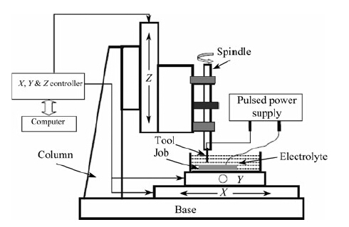 |
| Fig. 1 Schematics of the developed micro ECM set up |
The pulses (of width W and amplitude from 5 V to 10 V) from the pulse generator are supplied to the mosfet gate. A DC supply of amplitude V is supplied to the drain. As the mosfet is switched on, voltage pulses of amplitude V and width W are produced, which is applied across the electrodes to carry out the machining operations. Figure 2 illustrates the generation of pulse voltage by using the mosfet.
 |
| Fig. 2 Generation of pulsed DC voltage at the output of the mosfet |
Inter electrode gap control in micro-ECM process is very crucial for achieving precise machining of micro features. A hall current sensor has been used to convert the inter electrode gap current into proportional voltage, which is acquired by a data acquisition system and converted to an average voltage. A software program has been developed and engaged to compare this average voltage with the desired preset value of gap voltage, and accordingly the motion of the Z-stage for increasing or decreasing of the gap width is decided by the program. In this way the automatic gap control operation is performed during the machining operation. 3 Experimental
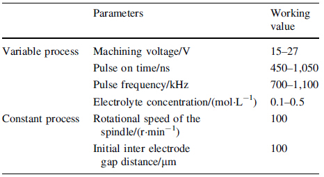
In the present investigation, 60 μ thickness 304 stainless steel sheets have been used as work piece. The high speed steel bar of 250 μ radius has been used as tool, and dilute H2SO4 solution is used as electrolyte. Different variable and constant experimental parameters are listed in Table 1. At a time, one parameter has been varied while others are kept at constant level, to see the influence of the specific variation on the taper angle of the machined hole. All other parameters, such as electrolyte agitation rate, inter electrode gap distance, RPM of tool rotation, are maintained uniformly in all experiments. The tool is rotated at 100 r/min, and at the same time it is given with sinking motion to maintain an equilibrium gap distance between the electrodes, while the micro hole machining operation is performed. The set up arrangement for performing the experiments is shown in Fig. 1. Different ranges of experimental parameters are selected by conducting pilot experiments and the values are chosen in such a way that, at the maximum value of the variable parameters, spark machining does not start. At each parameter setting, the experiments have been repeated thrice to minimize the error.
Figure 3 shows the captured waveforms during the machining of circular micro holes. The waveform a represents the pulse voltage which is supplied at the gate of the mosfet, and the waveform b represents the actual machining waveform which is acquired across the electrodes. The material removal takes place due to the charging and discharging of the dual layer capacitor which is formed on the surface of both electrodes [18]. During the pulse on time, the dual layer capacitor charges and during the pulse off time the dual layer capacitor discharges. This charging and discharging of the capacitor at the interface induce current flow in the circuit, and thus the material removal takes place. In Fig. 3, the dual layer capacitor can not discharge fully due to the limited pulse off time of the pulsed power supply.
 |
| Fig. 3 Plots of waveform captured during micro ECM |
Figures 4-6 show the SEM images of a few machined micro holes, at their entry and corresponding exit, with the variation of machining voltage with other parameters kept at fixed levels. The irregularity appears on the surface due to the adherence of foreign particles to the surface while the SEM images are taken. In these images, the shape of the machined hole is not circular because of the following reasons: i) the eccentric rotation of the cylindrical tool, ii) the surface of the stainless steel sheet (work piece) was not perfectly flat and perpendicular to the axis of the cylindrical tool, while the holes were machined, iii) problems in mounting the work piece while the SEM images were taken. The taper angle of the machined hole has been measured and its variation with the process parameters is illustrated in corresponding plots. In Figs.5 and 6, the plots are similar in nature and indicate that the taper angle does not vary significantly above 18 V and 600 ns, giving very stable machining. The nature of graph shows that the minimum value lies before the starting point of the selected range of applied voltage and pulse on time, but large variation in taper angle is found when one moves from Exp.1 to Exp. 2, indicating unstable machining. Experiments were also conducted to machine holes below the machining voltage of 15 V (see Fig. 7) and below the pulse on time of 450 ns (see Fig. 8). However it took several hours to make a single hole.
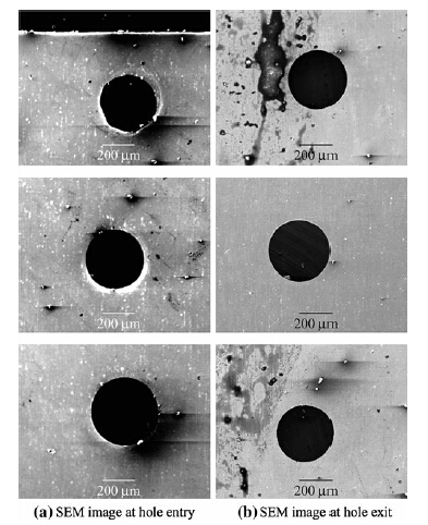 |
| Fig. 4 SEM images of the micro holes at the entry and exit at 15 V, 700 kHz, 600 ns, 0.1 mol/L H2SO4 |
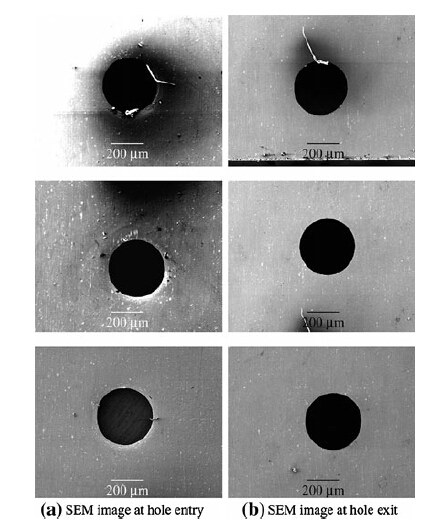 |
| Fig. 5 SEM images of the micro holes at the entry and exit at 18 V, 700 kHz, 600 ns, 0.1 mol/L H2SO4 |
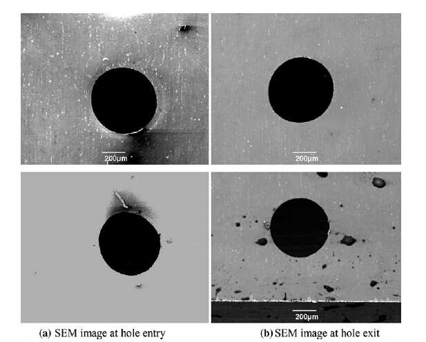 |
| Fig. 6 SEM images of the micro holes at the entry and exit at 21 V, 700 kHz, 600 ns, 0.1 mol/L H2SO4 |
 |
| Fig. 7 Variation of taper angle with machining voltage |
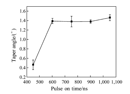 |
| Fig. 8 Variation of taper angle with pulse on time |
In the machining hole by micro-ECM process, the material is dissolved from the side wall and the bottom surface of the hole simultaneously. The machining of side wall leads to taper formation and machining of the bottom surface leads to the increase of hole depth. Hence the increase of machining time leads to the increase in taper angle of the holes. In Fig. 9, at low frequency (700 kHz), the total time consumption for making a hole is maximum, which leads to high taper angle of the hole. The graph follows a decreasing trend up to 1, 000 kHz and beyond that the taper angle increases. The rate of electrochemical reaction is directly proportional to the pulse frequency. Above 1, 000 kHz, the effect of electrolyte flushing is not sufficient to remove all the debris from the bottom gap (gap between the flat end of the tool and the bottom surface of the machined hole) of the cylindrical tool, which increases the over machining time and leads to increase in the taper angle of the hole.
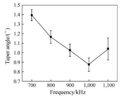 |
| Fig. 9 Variation of taper angle with pulse frequency |
In Fig. 10, the optimum H2SO4 concentration is 0.4 mol/L, where the minimum value of taper angle is observed. The present flushing condition can maintain the uniform reaction rate up to 0.4 mol/L H2SO4. When the flushing is insufficient, the reaction rate at the periphery wall is much higher than that at the bottom surface which leads to the increase in the taper angle. For fine tuning of the input parameters to get minimum taper angle, further experimentations are required. The time consumption for machining holes varies from a maximum of 10 min to a minimum of 30 s approximately.
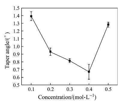 |
| Fig. 10 Variation of taper angle with concentration of H2SO4 |
The experiments of machining circular micro-holes have been performed successfully with a newly developed set up by varying experimental parameters. The analysis of the experimental results has been carried out and the following conclusions are drawn.
Machining of micro holes with tool rotation gives circular holes, but extreme care must be taken when the cylindrical micro tool is fixed on the spindle of the set up to minimize the eccentric rotation of the tool, which in turn increases the diameter of the machined hole. The flushing condition in the inter electrode gap is very important for obtaining a minimum taper angle. In the present work, the minimum value of the taper angle is achieved at 0.4 mol/L H2SO4, 700 kHz, 600 ns, 21 V for stainless steel sheets and HSS tool, which may be varied when the electrodes and electrolyte combination changes. Hence for each combination of electrode and electrolyte, experiments are needed to be performed for parametric optimization.
| 1. | Bhattacharyya B, Munda J, Malapati M (2004) Advancement in electrochemical micro-machining. Int J Mach Tools Manuf 44(15):1577-1589 |
| 2. | Masuzawa T (2000) State of the art of micromachining. Ann CIRP 49(2):473-488 |
| 3. | Bhattacharyya B, Munda J (2003) Experimental investigation into electrochemical micromachining (EMM) process. J Mater Process Technol 140:287-291 |
| 4. | Bhattacharyya B, Malapati M, Munda J (2005) Experimental study on electrochemical micromachining. J Mater Process Technol 169(3):485-492 |
| 5. | Bhattacharyya B, Malapati M, Munda J et al (2007) Influence of tool vibration on machining performance in electrochemical micro-machining of copper. Int J Mach Tools Manuf 47(2): 335-342 |
| 6. | Zhang Z, Zhu D, Qu N, Wang M (2007) Theoretical and experimental investigation on electrochemical micromachining. Microsyst Technol 13:607-612 |
| 7. | Kim BH, Na CW, Lee YS et al (2005) Micro electrochemical machining of 3D micro structure using dilute sulpfuric acid. Ann CIRP 54(1):191-194 |
| 8. | Kim BH, Park BJ, Chu CN (2006) Fabrication of multiple electrodes by reverse EDM and their application in micro ECM. J Micromech Microeng 16:843 |
| 9. | Ahn SH, Ryu SH, Choi DK et al (2004) Electro-chemical micro drilling using ultra short pulses. Precis Eng 28:129-134 |
| 10. | Cagnon L, Kirchner V, Kock M et al (2003) Electrochemical micromachining of stainless steel by ultra short voltage pulses. Z Phys Chem 217:299-313 |
| 11. | Munda J, Malapati M, Bhattacharyya B (2007) Control of microspark and stray-current effect during EMM process. J Mater Process Technol 194(1-3):151-158 |
| 12. | Sen M, Shan HS (2005) A review of electrochemical macro- to micro-hole drilling processes. Int J Mach Tools Manuf 45(2): 137-152 |
| 13. | Li Y, Zheng Y, Yang G, Peng L (2003) Localized electrochemical micromachining with gap control. Sens Actuators A 108(1-3): 144-148 |
| 14. | Jahan MP, Wong YS, Rahman M (2009) A study on the quality micro-hole machining of tungsten carbide by micro-EDM process using transistor and RC-type pulse generator. J Mater Process Technol 209(4):1706-1716 |
| 15. | Lim HS, Wong YS, Rahman M et al (2003) A study on the machining of high-aspect ratio micro-structures using micro- EDM. J Mater Process Technol 140(1-3):318-325 |
| 16. | Asad ABMA, Masaki T, Rahman M et al (2007) Tool-based micro-machining. J Mater Process Technol 192-193:204-211 |
| 17. | Rahman AA, Mamat A, Wagiman A (2009) Effect of machining parameters on hole quality of micro drilling for brass. Mod Appl Sci 3(5):221-230 |
| 18. | Schuster R, Kirchner V, Allongue P et al (2000) Electrochemical micromachining. Science 289(5476):98-101 |
 2013, Vol. 1


