The article information
- Li Song-Sheng, Shen Yuan, He Qiang
- Study of the thermal influence on the dynamic characteristics of the motorized spindle system
- Advances in Manufacturing, 2016, 4(4): 355-362.
- http://dx.doi.org/10.1007/s40436-016-0158-1
-
Article history
- Received: 17 March, 2016
- Accepted: 13 October, 2016
- Published online: 28 November, 2016
2 School of Mechanical Engineering, Anyang Institute of Technology, Anyang 455000, Henan, People's Republic of China
As modern computer numerical control (CNC) machine tool requires high-speed, high-precision, and high efficiency, the high speed motorized spindle has become the most preferred key function part of metal cutting machine tool. High speed motorized spindle has great influence on the overall technical performance of the machine tools, and the main factor that affects the dynamic characteristics and the dynamic accuracy of the motorized spindle is the severe internal heat generation [1, 2]. Therefore, in order to study the thermal influence on the modal characteristics, it is crucial to analyze the internal heat generation and the thermal characteristics of the motorized spindle.
Previous researches of the machine tool spindle system focus on the thermal characteristic or modal characteristics. On the study of dynamic characteristics, Cai et al. [3] studied modal analysis of heavy-duty mechanical spindle under multiple constraints. They modeled and analyzed the heavy-duty mechanical spindle by finite element method (FEM). Kumar and Schmitz [4] applied receptance coupling substructure analysis (RCSA) to test the spindlemachine dynamics. Jin [5] discussed the modal and harmonic response characteristics of the motorized spindle based on the three-dimensional FEM model, and the maximum dynamic displacement of the spindle is also analyzed. Xu and Jiang [6] established motion equations for rotor-bearing system considering five-degree-of-freedom (5DOF) and verified it on an experimental platform with externally pressurized air bearings. In the thermal characteristic studies, Chen et al. [7] proposed a thermalmechanical error model to predict the variation of motion error induced by thermal effect. Liu et al. [8] introduced a differentiated multi-loops bath recirculation system to solve the thermal errors of precision machine tool. Ma et al. [9] studied the high-speed spindle system by numerical and experimental method, and their result showed that radial and axial stiffness of bearings had great influence on the thermal deformation of the spindle system. Chang and Chen [10] proposed a direct displacement measuring system, which could accurately monitor and compensate the thermal growth. Anandan and Ozdoganlar [11] found that all the thermal characteristic, rotating speed and span had impact on the performance of the ultra-high-speed (UHS) micromachining spindle. In the thermo-mechanical studies, based on Timsheko beam theory and the finite element approach, Zahedi and Movahhedy [12], Li and Shin [13] studied the dynamic characteristic and the thermal behavior of high speed spindles. Holkup et al. [14] considered the transient changes of different parameters in their thermomechanical model, and the results showed that the bearing stiffness and contact forces change caused by temperature change could lead to seizure and damage of the spindle.
In this paper, the modal characteristics of the motorized spindle are studied under the steady state in comparison with the static state. The thermal characteristics, the vibration modes and natural frequencies are also analyzed. The thermal characteristic model is established to numerically simulate the thermal characteristic of the motorized spindle system, and the thermal deformation of the motorized spindle system is obtained by the thermalstructure coupling simulation. The thermal deformation of the rotor and the bearing units is extracted to analyze the bearing stiffness change, and then the modal characteristics are analyzed in static and thermal steady state condition. The model is verified by thermal deformation experiments and hammer exciting modal experiments.
2 Thermal characteristic model of the motorized spindle 2.1 Thermodynamic analysis theoryThe general equation for steady-state thermodynamic analysis in the finite element theory is shown as
where Kt is the conduction matrix including the heat coefficient, the convection coefficient, the radiation coefficient and the shape factor; I is element temperature vector; Q is element heat flux vector including heat generation.
2.2 Heat generation in the bearings and the built-in motor(ⅰ) Heat generation in the bearings
Palmgren gives the formula for calculating the friction heat generated between the rolling elements and the rings [15].
where M is the total friction torque of the bearings (N·mm), n the rotating speed of the bearing inner race (r/min), and Qf is the heat generated in the bearings (W). The total friction torque of the bearings consists of the two terms:
where M1 is the friction torque related to the rotating speed, lubrication and bearing type, and it can be calculated as
where f0 is a coefficient related to the bearing type and lubrication. For the angular contact ball bearings lubricated by grease, f0=2; dm is the mid-diameter of the bearings; v is the kinematic viscosity of the lubricant at operating temperature. For the ball bearings lubricated by grease it means that the base oil kinematic viscosity of grease is valid for a short period after greasing [16]. M2 is the friction torque related to the load of the bearing. It can be calculated as
where f1 is the load coefficient, and for the angular contact ball bearings f1=0.001; P1 is the equivalent load of the bearings.
ⅱ Heat generation in the motor
Copper loss is the electric energy loss caused by the resistance of the rotor and the stator winding, given by [17]
where θ is number of phases of the motor, Ip the phase current of the rotor or stator winding (A), r the resistance of the single-phase rotor or stator winding (X), ρp the resistivity of the winding (X·m), Lp the length of each phase winding (m), S the cross-sectional area of the conductor (m2).
Iron loss (magnetic loss) is another loss of the motor, which can be calculated as [17]
where P1/50 is the iron loss coefficient when B=1 T and f=50 Hz, mc the mass (kg), B the magnetic flux (T), ka is the losses factor considering metallurgical and manufacturing processes.
2.3 Heat transfer boundary conditionThe cross-section of the cooling water channel is rectangular cross-section and the cooling water flowing state can be described by the Reynolds number (Re)
where A is the cross-sectional area, x the wetted perimeter of the cross-section, V the mean flow velocity of the fluid.
When Re<2 200, the flow state is laminar flow, and the Nusselt number is given by [18]
 (10)
(10) where L is the length of the heat sink, d the characteristic length of the flow pass diameter (d=4R), Prw calculated according to the wall temperature Tw, Prf the average value of Prandlt number. The experimental verification scope: 1.41<(Prf/Prw)<18.2, Ref<2 200.
For 2 200<Re<10 000, the average heat transfer coefficient of air is given by [18]
 (11)
(11) the experimental verification scope: 1.5<prf<500, 0.05<(prf/prw)<20, 2 200<Ref<10 000.
The Nusselt number of rotating surface is given by [19]
 (12)
(12) where 
The heat transfer coefficient of the forced convection is given by
 (13)
(13) where Nu is the Nusselt number of the fluid that can be calculated by the equations above, and λw is the thermal conductivity of the fluid.
The heat transfer of the motorized spindle surface includes convection and radiation. The entire thermal resistance can be seen as two parallel thermal resistances, so the entire heat transfer equals to the sum of the convection and radiation heat transfer,
 (14)
(14) where Φ is the entire heat transfer, Φc the convection heat transfer, ΦR the radiation heat transfer. According to Ref. [20], the heat transfer coefficient of the motorized spindle surface is 27 W/(m2·℃).
3 Modal characteristic model of the motorized spindle system 3.1 Dynamic analysis theoryThe balance equation of dynamic problems is
 (15)
(15) where M is the mass matrix, C the damping matrix, K the stiffness matrix, x the displacement vector, F(t) the force vector, 

Modal analysis of motorized spindle system is a special form of the vibration characteristic analysis. The influence of structural damping on the modal and vibration mode is very small, so the expression of the modal vibration matrix is shown as
 (16)
(16) The free vibration of the structure is harmonic vibration, so the displacement vector function is sine function
 (17)
(17) Inserting Eq. (17) into Eq. (16) and rearranging as
 (18)
(18) The eigenvalue of the equation is ωi2, and ωi is the natural circular frequency, so the natural frequency can be given by 
The thermoelastic theory shows the relationship of the thermal influence and the dynamic characteristics. The coupled thermoelastic constitutive equations are [21]
 (19)
(19)  (20)
(20) where ε is the total strain vector; D is the elastic stiffness matrix; σ is the stress vector; α is the vector of coefficients of the thermal expansion; ΔT is temperature change; S is entropy density; ρ is the density; Cp is the specific heat constant stress; T0 is the absolute reference temperature.
Applying the balance equation of the dynamic problems and the steady-state thermodynamic equation coupled by the thermoelastic cons titutive equations, the following finite element matrix equation is
 (21)
(21) where Ct is the element specific heat matrix; Ctu is the element thermoelastic damping matrix; Kut is the element thermoelastic stiffness matrix; F is the sum of the element nodal force and the element pressure vectors.
3.4 Bearing stiffness and deformation calculationBearing stiffness is an important parameter to calculate the modal characteristics of the spindle. Angular contact ball bearing is more commonly used in motorized spindle. It has high limited speed and can bear axial load as well as radial load.
Radial stiffness of angular contact ball bearing can be given by [22]
 (22)
(22) where kr is the radial stiffness (N/mm), z number of rolling elements, Db the diameter of the rolling elements (μm), Fa the axial load (N).
When the axial load Fa is known, axial stiffness of angular contact ball bearing can be given by [22]
 (23)
(23) where ka is the axial stiffness (N/mm).
The stiffness of angular contact ball bearing has a close relationship with the axial and radial deformation of the bearing and the bearing load. The assumed load (K) of angular contact angle contact ball bearing is given in Ref. [22] when its elastic deformation is δa, the assumed load can be calculated by
 (24)
(24) where Fδ is the radial load generated by deformation (N), and Cδ is the constant of deformation.
 (25)
(25) where G is the raceway groove curvature center coefficient, G=fi + fe-1; fi is the internal raceway groove curvature radius coefficient; fe is the external one. These parameters are related to the selection of bearing.
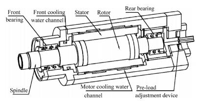
4 Physical modelFigure 1 shows a high speed motorized spindle with adjustable preload. The thermal-structure of FEM model should be properly simplified. The rotor and the stator can be simplified as thick cylinders with evenly distributed heat source. Squirrel-cage three-phase asynchronous motor is often used in motorized spindle motor. In the simplified model, the two ends of the stator are considered as copper and the rotor ends are aluminum, while the middle part of them is silicon steel. The rolling elements of the bearing can be equivalent to a ring with the same cross-sectional area. The wiring structure, the bolts, bolt holes and other tiny structures are neglected. The thermal contact resistance of the contact parts in the simplified model is 0. All materials are isotropic materials.
|
| Fig. 1 The simplified model of the motorized spindle |
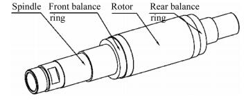
The dynamic characteristic of the motorized spindle system is influenced by bearing characteristics and the geometric of the spindle, etc. In the modal analysis module of the ANSYS Workbench 15.0, the bearing is simplified to four uniformly distributed springs with stiffness and damping. In this case, the front motorized spindle bearing is fixed, and the rear bearings can move in the axial direction. The boundary conditions are applied to the front bearing shaft shoulder by which the front bearings are elastic supported, and the stiffness of the elastic support is the axial stiffness of the front bearings. In addition, it is considered that the material of the front and rear balancing rings are the same as the spindle, and the simplified method of the spindle unit is not different as the thermal-structure coupling model. The simplified model is shown in Fig. 2.
|
| Fig. 2 The three-dimensional model of the spindle unit |
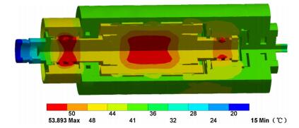
To obtain the thermal characteristic of the simplified model, the ANSYS Workbench 15.0 commercial code is applied. The environment temperature of the simulation is 24 ℃ and the rotating speed is 20 000 r/min. The internal temperature of the motorized spindle is shown in Fig. 3. As can be seen from Fig. 3, the main heat sources of the motorized spindle are the rotor, the stator, and the bearings. The front cooling water passage takes away a portion of the heat thus the surrounding temperature is relatively low.
|
| Fig. 3 The temperature distribution of the motorized spindle |
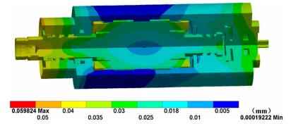
The thermal deformation of the motorized spindle is shown in Fig. 4. It shows that the thermal deformation of the motorized spindle begins from the center of the spindle. The deformation is gradually accumulated, and the deformation of the stator is larger. Front and rear bearings are the parts of high temperature and large deformation in the motorized spindle. The thermal deformation of the ends of the motorized spindle is larger due to the deformation accumulation. The cooling water passage of the motor takes away a portion of the heat, thus the thermal deformation is relatively small.
|
| Fig. 4 The thermal deformation of the motorized spindle |
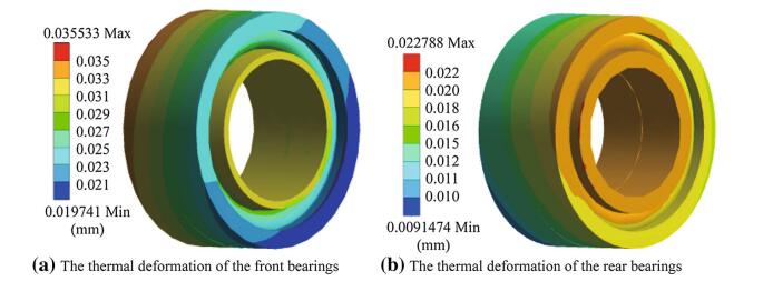
As shown in Fig. 5, the main thermal deformation direction of the stator and the rotor is radial deformation, and the deformation is gradually accumulated from center to edge. The front and rear bearing thermal deformation is shown in Fig. 6. The differences of the front bearings inner ring and the outer ring thermal deformation are around 4 μm and 7 μm, respectively, and the differences of the rear bearings are around 2 μm and 4 μm. The front bearings thermal deformations are larger than the rear bearings both in radial and in axial directions.

|
| Fig. 5 The thermal deformation vector diagram of the motorized spindle |
|
| Fig. 6 The thermal deformation of the bearings |
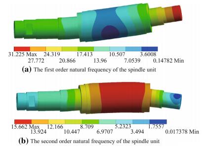
Commonly used in engineering is the first two order natural frequency of the rotor part. For the static rotor, the axial preload is 60 N, and the simulation result the first two order natural frequency is shown in Fig. 7. The first order natural frequency of the spindle unit is 804 Hz with the vibration mode swinging up and down at the right end. The second order natural frequency of the spindle unit is 1 765 Hz with the vibration mode swinging up and down in the middle.
|
| Fig. 7 The vibration mode of the spindle unit under the static state |
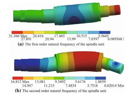
With the simulation results plugging into Eqs. (17) and (18) and the diagram provided in Ref. [16], we can get the additional load of the front or the rear bearings that is generated by thermal deformation. Then the bearing stiffness under the thermal static state can be calculated by Eqs. (15) and (16). Since the maximum thermal deformation is about 0.06 mm which is relatively small in comparison with the size of the spindle unit, it is ignored when the spindle mode is analyzed. The numerical result is shown in Fig. 8, and the first order natural frequency of the spindle unit is 828 Hz and the second one is 1 940 Hz. Compared with the static state, the vibration modes are the same, and the relative deformation is not very large. It shows that the thermal state of the motorized spindle system mainly affects the natural frequency of the rotor.
|
| Fig. 8 The vibration mode of the spindle unit under thermal steady state |
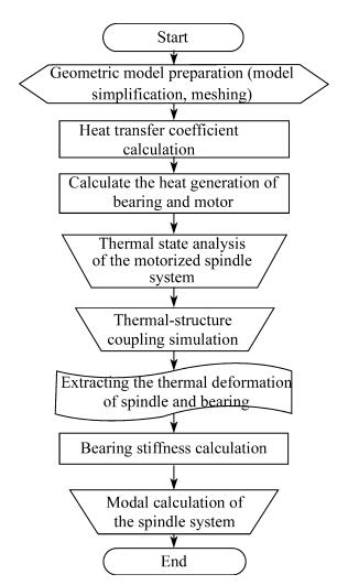
The numerical simulation step can be summarized in Fig. 9.
|
| Fig. 9 The process diagram of the numerical simulation |
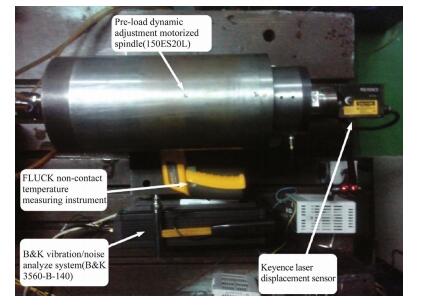
It is important to consider many factors when choosing the experimental instruments. The purpose of the experiments is to investigate the thermal characteristic impact on the modal characteristic. As shown in Fig. 10, the experimental instruments include a B & K vibration/noise analysis system (B & K 3560-B-140), a Keyence laser displacement sensor, and a FLUKE non-contact temperature measuring instrument. The motorized spindle is pre-load dynamic adjustment motorized spindle (150ES20L).
|
| Fig. 10 Experimental instruments |
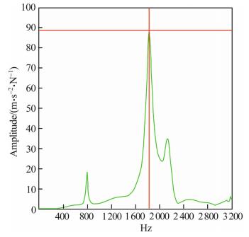
The axial load is 60 N when doing the modal experiment of the static spindle by hammer exciting. Radial excitation is performed on the spindle end by the hammer, and the sensor is also in radial direction. The frequency response curve is shown in Fig. 11. The first order natural frequency of the static spindle unit is 800 Hz and the second one is 1 810 Hz. Compared to the numerical results, the two results of the first order natural frequency are close and the second natural frequency of the numerical result is lower.
|
| Fig. 11 The frequency response curve of the static spindle |
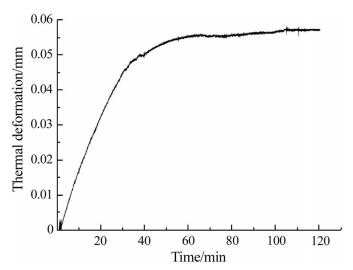
The motorized spindle speed is set at 20 000 r/min. Figure 12 shows that the spindle thermal deformation changes with time and the maximum deformation is 0.057 mm. In the first 40 min, the thermal deformation of the motorized spindle rises fast as the temperature rises, then the trend becomes slow. The motorized spindle system enters into thermal steady state at about 110 min. The numerical result of the thermal result is around 0.040 mm, which is smaller than the experimental values due to the fact that rolling elements of the bearing are simplified to a ring with the same cross-sectional area, and the simplified bearing model cannot be axial sliding on the spindle while the actual one has some axial sliding. In the experiment, the temperature of the three key points (front, middle and rear point on the spindle) is selected to compare with the numerical result, and the numerical result is about 10% higher than that of the test temperature.
|
| Fig. 12 The thermal deformation trend of the spindle |
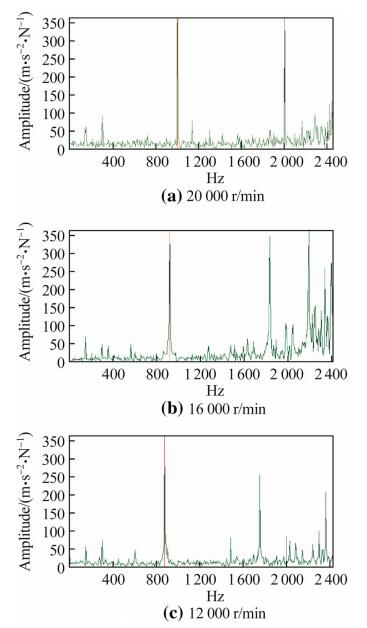
The thermal steady state frequency response curves under different rotating speeds are shown in Fig. 13. It can be found that the natural frequency of the motorized spindle system increases after increasing the rotating speed. All of the dynamic natural frequencies are higher than the static state one. It is due to that the rotating speed rises up the temperature of the system and the thermal deformation of the spindle becomes larger, which causes the stiffness of the bearings growing. In addition, the first order natural frequency is 872 Hz when the rotating speed is 20 000 r/min in the experiment, and the numerical and the experimental results are essentially consistent. The second order natural frequency is 1 745 Hz, and the numerical result is a little higher. The numerical error is derived from the fact that the simulation model only considers the variation of stiffness caused by the thermal deformation while ignoring the influence of other factors on the bearing dynamics. Besides, the numerical model is simplified.
|
| Fig. 13 The frequency response curve of the thermal steady state spindle |
The steady state temperature field, thermal deformation and the vibration modal change of the motorized spindle system are analyzed by the numerical model, and the dynamic characteristics of the system are also studied by the experimental method.
(ⅰ) The numerical result shows that the bearings and the motor are the main heat source and their temperature is higher. The thermal deformation gradually accumulated from the center to the edge, which caused the fact that the thermal deformations of the motorized spindle ends were relatively large.
ⅱ The thermal characteristic mainly influences the natural frequency of the spindle, while the effect on the vibration mode is smaller.
(ⅲ) The motorized spindle system will enter into a thermal steady state at about 110 min at the startup phase, and the natural frequency of the spindle will go up as the rotating speed rises.
| 1. | Krulewich DA(1998) Temperature integration model and measurement point selection for thermally induced machine tool errors. Mechatronics, 8(4), 395-412 doi:10.1016/S0957-4158(97)00059-7 |
| 2. | Meng J, Chen XA, Chen F(2009) Experimental modality analysis of high speed motorized spindle. J Mach Des, 26(6), 70-72 |
| 3. | Cai LG, Ma SM, Zhao YS, et al(2012) Finite element modeling and modal analysis of heavy-duty mechanical spindle under multiple constraints. J Mech Eng, 48(3), 165-173 doi:10.3901/JME.2012.03.165 |
| 4. | Kumar UV, Schmitz TL(2012) Spindle dynamics identification for receptance coupling substructure analysis. Precis Eng, 36(3), 435-443 doi:10.1016/j.precisioneng.2012.01.007 |
| 5. | Jin MG (2009) System design and analysis of dynamic and static characteristics of high-speed motorized spindle. Dissertation, Jilin University, Jilin |
| 6. | Xu C, Jiang S(2015) Dynamic analysis of a motorized spindle with externally pressurized air bearings. J Vib Acoust, 137(4), 041001 doi:10.1115/1.4029675 |
| 7. | Chen D, Bonis M, Zhang F, et al(2011) Thermal error of a hydrostatic spindle. Precis Eng, 35(3), 512-520 doi:10.1016/j.precisioneng.2011.02.005 |
| 8. | Liu T, Gao W, Tian Y, et al(2014) A differentiated multi-loops bath recirculation system for precision machine tools. Appl Therm Eng, 76, 54-63 |
| 9. | Ma C, Yang J, Zhao L, et al(2015) Simulation and experimental study on the thermally induced deformations of high-speed spindle system. Appl Therm Eng, 86, 251-268 doi:10.1016/j.applthermaleng.2015.04.064 |
| 10. | Chang CF, Chen JJ(2009) Thermal growth control techniques for motorized spindles. Mechatronics, 19(8), 1313-1320 doi:10.1016/j.mechatronics.2009.06.012 |
| 11. | Anandan KP, Ozdoganlar OB(2013) Analysis of error motions of ultra-high-speed (UHS) micromachining spindles. Int J Mach Tools Manuf, 70(7), 1-14 |
| 12. | Zahedi A, Movahhedy MR(2012) Thermo-mechanical modeling of high speed spindles. ScientiaIranica, 19(2), 282-293 |
| 13. | Li H, Shin YC(2004) Integrated dynamic thermo-mechanical modeling of high speed spindles, part, 2004, 1:model development. J Manuf Sci Eng, 126(1), 148-158 doi:10.1115/1.1644545 |
| 14. | Holkup T, Cao H, Kolář P, et al(2010) Thermo-mechanical model of spindles. CIRP Ann-Manuf Technol, 59(1), 365-368 doi:10.1016/j.cirp.2010.03.021 |
| 15. | Palmgren A (1959) Ball and roller bearing engineering. Skf Industries Inc, Philadelphia |
| 16. | Harris TA (2006) Rolling bearing analysis. Wiley, Hoboken |
| 17. | Gieras JF, Gieras JF(2002) Permanent magnet motor technology. IEEEXPLORE.IEEE.ORG, 2, 1181-1187 |
| 18. | Yang SM, Tao WQ(2006) Heat transfer. Higher Education Press , Beijing |
| 19. | Uhlmann E, Hu J(2012) Thermal modelling of a high speed motor spindle. Procedia Cirp, 1(9), 313-318 |
| 20. | Chen YN, Chen ZH(1989) Fundamental theory of machine tool thermal character. China Machine Press , Beijing |
| 21. | Nye JF(1957) Physical properties of crystals:their representation by tensors and matrices. Clarendon Press , Oxford |
| 22. | Dan S(1993) Machine tool rolling bearing application manual. Beijing , China Machine Press |
 2016, Vol. 4


