 2016, Vol. 4
The article information
- Astarita Antonello, Coppola Mario, Esposito Sergio, Liberini Mariacira, Maio Leandro, Papa Ilaria, Scherillo Fabio, Squillace Antonino
- Experimental characterization of Ti6Al4V T joints welded through linear friction welding technique: microstructure and NDE
- Advances in Manufacturing, 2016, 4(4): 305-313.
- http://dx.doi.org/10.1007/s40436-016-0160-7
-
Article history
- Received: 20 July, 2016
- Accepted: 21 October, 2016
- Published online: 2 December, 2016


2 Fox Bit srl, viale Luraghi presso consorzio Il Sole, 80038 Pomigliano d'Arco, NA, Italy
3 Leonardo Company S. p. A. -Aircraft Division, Engineering-AT & D, Manufacturing and Assembly Research and Development, Viale dell'Aeronautica, s/n, 80038 Pomigliano d'Arco, NA, Italy
4 Department of Industrial Engineering-Aerospace Division, University of Naples "Federico Ⅱ", Via Claudio, 21, Naples, Italy
The solid state welding techniques (such as friction stir welding, linear friction welding, diffusion bonding) are finding an increasingly widespread use in several industrial fields, which thanks to several intriguing reasons: (i) these techniques allow to weld high strength alloys such as titanium and aluminum alloys [1, 2]; (ii) it is possible to obtain high strength transition joints between dissimilar materials, such as copper to aluminum or steel to titanium [3, 4]; (iii) it is possible to obtain joints with higher mechanical performances compared to joints produced through conventional welding techniques [5-7]. Particularly interesting is the linear friction welding (LFW), in this process the bonding of the parts to be joined is achieved by means of a relative reciprocating motion under compressive axial force [8]. This process has four distinct phases: first, transition, equilibrium and forging [9]. The heat is produced through the friction between the components to be welded, and this heat leads to the plasticization of the material at the interface. This deformed material is pushed along the weld edges and induces the formation of a flash (upset metal). When the necessary amount of deformation has been reached, a forging load is imposed to obtain an effective weld bead. Moreover the joints produced through this technique show very narrow thermo-mechanically affected zone (TMAZ) and heat affected zone (HAZ). Therefore, in order to achieve a successful friction welded joint, it is necessary to induce a certain level of plastic deformation into both components in spite of the extensively differing deformation behavior. This produces a complex microstructure within the joint, resulting from the combination of the forging force and the high temperature. There are several papers in literature dealing with the study of LFW dissimilar joints [10, 11], but only few of them dealing with the study of the joining of grade 5 titanium to AISI 316 [12, 13]. The study dealing with the LFW joining of Ti6Al4V is also available in Refs. [14, 15]. Despite these premises there are few papers investigating the nondestructive evaluation of linear friction welded titanium joints. Common non-destructive techniques include fluorescent penetrating fluid inspection [16], ultrasonic testing, acoustic emission [17], X-ray [18], eddy current, magnetic methods [19], and ultrasound-excited infrared thermography [20]. Many of these conventional non-destructive testing (NDT) methods can be easily used for the detection of volumetric faults, but sometimes they are insensitive and impractical for the more challenging root flaws [21]. For instance, in order to obtain satisfactory results, the fluorescent penetrating fluid inspection method requires access to the back side of the butt-joint structure [17]. Digital X-ray radiography and lock-in infrared thermography have been exploited to examine sub-surface tunnel defects in FSW joints [22, 23]. In recent years, an eddy current NDT of FSW root flaws has been reported [24, 25]. Santos et al. [26] have stated that eddy currents could detect superficial defects at about 60 mm deep from the far side, i.e., the side that contains the root flaw. The use of conventional ultrasonic techniques has shown that it is not straightforward to detect small defects at the bottom of the weld or tiny root flaws in friction stir welded joints [27]. To transcend this, several studies have invested in advancing and optimizing these ultrasonic techniques [28, 29]. The ultrasonic control can be particularly useful for the detection of defects in the LFW joints. For instance a typical application of the LFW is the joining of the blades with the disk in the fabrication of turbine engines [30], for this application the possibility to detect the defects through a non destructive evaluations (NDE), such as the ultrasonic control, can be very useful. The aim of this paper is to study the effectiveness of the ultrasonic control in the detection of defects in Ti6Al4V T-joints welded through LFW technique.
2 ExperimentalAiming to prove the effectiveness of the ultrasonic control in detecting the welding defects, different joints in different processing conditions were manufactured to simulate the diverse defects and metallurgies that could be obtained through the LFW process. The ultrasonic control was effectuated on all the joints. After that a full experimental campaign, including microstructural observation, was carried out on the joints to confirm the results of the ultrasonic control. In the hereinafter the whole experimentation will be presented and discussed in details.
2.1 Joints manufacturingIn this research activity Ti6Al4V ingots were used as base material, both the mechanical properties and the chemical composition were fully available in literature and were not here reported for the sake of brevity [31]. The specimens to be welded were machined from the ingots, parallelepiped blocks in two different dimensions were produced: blocks "A" 64 mm × 26 mm × 8.6 mm and blocks "B" 40 mm × 26 mm × 11 mm (the welding configuration is sketched in Fig. 1b). Such a decision, to weld together pieces of different dimensions, to simulate some real aeronautical applications (e.g., bumpers or blisks). The alternate linear movement was imposed to the block "A" while the force was applied to the block "B". The movement was imposed from left to right. After the machining no further preparation of the blocks before the welding is required. The contact area between the two pieces during the welding is 26 mm × 11 mm. The welding process was effectuated by means of an in-house developed LFW-fixture, as shown in Fig. 1.

|
| Fig. 1 a LFW dedicated fixture used in this research activity and b sketch of the welding configuration (dimensions given in millimeter) |
The welding equipment consists of four main components: the hydraulic unit, a battery of accumulators, the electrical panel and the LFW fixture. The fixture is composed by a support structure on which two hydraulic pistons are placed, arranged orthogonally between them and to which are connected the actuators and the clamps that grip the two parts to be welded. The transverse actuator can execute a rectilinear motion with a maximum frequency value of 70 Hz and it can also apply a maximum compression load of 70 000 N, the other actuator can exert a maximum value of the forging load of 100 000 N. The hydraulic unit is constituted by a gear pump fed and by a 18 kW asynchronous motor. The motor has to feed the battery of accumulators with the engine oil at a pressure of 20 MPa. The battery of six accumulators, with a total capacity of 1 20L, has the aim to ensure the supply of oil to the transverse actuator during welding process.
In order to obtain joints with different characteristics (i.e., joints free from defects, joints with defects of different dimensions and positions, joints with different metallurgies) the main process parameters were varied in a wide range. Table 1 shows the process parameters adopted for all the different joints manufactured. An oscillation amplitude of 15 mm was adopted in all the tests. For each sample three different joints were manufactured and tested to ensure the repeatability of the process.
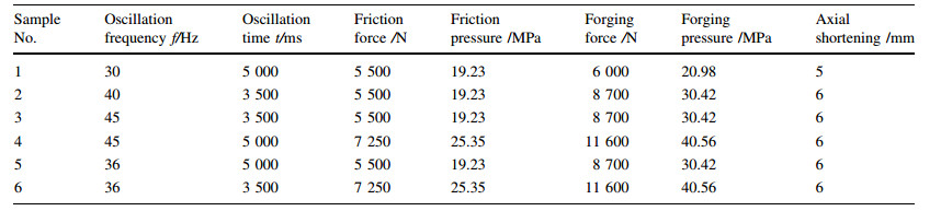
The process parameters were chosen on the basis of trials experiments (not reported here) for the sake of brevity and taking into account the previously mentioned literature. Wanjara and Jahazi [32] studied in details the LFW process for the Ti6Al4V and discussed the effect of the process parameters on the metallurgy of the joints, and a detailed review on the LFW process where a lot of information concerning the process parameters also could be found in Ref. [33]. Moreover, it can be seen from Table 1 that only two distinct values for the forging force are adopted because this parameter has less influence on the final characteristics of the joints with respect to the other process parameters, as pointed out by Grujicic et al. [34].
2.2 Ultrasonic controlThe joints were inspected by means of a US Multi2000 Pocket 16 × 64 equipment. The inspection was carried out by using a single probe, DS 6 HB 2-7 produced by KARL DEUTSCH, 5 MHz. The main technical features of the probe are given in Table 2. This low frequency probe (f=5 MHz) was chosen in order to obtain an important decrease of the signal attenuation and a more efficient measure [35].

The operational mode chosen was the reflection: the probe was used for the emission and the reception of ultrasonic waves. During the acquisition the pulse echo technique was adopted: short-duration ultrasound pulses were transmitted into the region to be studied, and the echo signals resulting from scattering and reflection were acquired and displayed. The depth of a reflective structure is inferred from the delay between pulse transmission and echo reception [36]. The data presentation method was a scan by which intelligence signals from a signal object located were displayed. As generally applied to pulse echo ultrasonic, the horizontal sweep is proportional to distance and the vertical one is proportional to amplitude. Thus the location and magnitude of acoustical interface are indicated as to depth below the transducer. The specimens were tested before and after the welding in order to evaluate the sample integrity and calibrate the acquisition system. By properly setting the gate, a fairly clear picture of the welded area is obtained, and then it is preceded successively to a correct sizing of the defect. Echo Max (abs) is the used detection mode: once the gate is set on the implementation of the scan, it will be registered only the maximum peak that surpasses it. So, using a non-welded component, the correct thickness is obtained (see Fig. 2) and the acquisition system is calibrated. The propagation velocity, equal to 5 000 mm/s, is registered.

|
| Fig. 2 Output of the ultrasonic control carried out on an "A" block used to calibrate the measurement system |
The sensitivity of the control, i.e., the minimum detectable defect size d*, strictly depends on the wavelength of the ultrasound beam, λ. A defect is detectable only when its transverse dimension, with respect to the propagation direction, is at least equal to λ/4. Smaller defects cannot be observed. Due to the material and probe characteristics, the control can display defects (discontinuity or inclusions) whose transverse dimension is bigger than two tenths of a millimeter (λ/4=0.25 mm). In order to scan the welded zone, the T-joint specimens were cut to intercept cracks on the cut surface. Figure 3 indicates the points where the ultrasound probe is positioned.

|
| Fig. 3 Points where the ultrasonic control was carried out, i.e., points where the probe was placed during the control |
The specimens for the metallographic observations were cut from the cross section of the joints by following the cutting scheme, as shown in Fig. 4. The specimens were cut by means of a metallographic precision cutting machine, mounted in a thermoset conductive resin, and then polished to a mirror like surface finishing. The specimens were etched using a hydrofluoridric acid solution. All the above mentioned procedures were carried out following the ASTM standards for metallography. Finally the prepared specimens were observed through a Hitachi TM3000 SEM. Moreover the dimension of the grains and the extension of the different metallurgical zones were measured through the image analysis software as done in previous works [37].

|
| Fig. 4 Cutting scheme of the joints to obtain the metallographic specimens |
Figure 5 shows a micrograph representing the microstructure of the base material. A bimodal microstructure can be observed, made of coarse α grains immersed in an α+β matrix. This kind of microstructure is typical of annealed Ti6Al4V ingots.

|
| Fig. 5 Cross section micrograph of the base material |
Concerning the final microstructure of the joints three main different metallurgical zones can be highlighted from the centre of the joint including the welding region, the TMAZ and the base material. Regarding the base material in this region the material retains the parent microstructure, i.e., retains the microstructure, as shown in Fig. 5. Figure 6 shows a micrograph of the microstructure observed in the TMAZ.

|
| Fig. 6 Cross section micrograph of the TMAZ (the arrow highlights the plunging direction during the welding) |
The microstructure of the TMAZ is made of α grains within an α+β matrix. The α grains are stretched along a direction that is quite perpendicular to the plunging direction of the welding process. The grains are deformed and are highly oriented. Moreover it is possible to assess that the longitudinal dimension of the α grains, which is an index of the crushing suffered from the same grains, depends on the number of cycles impressed to the samples. In this zone the grains are not fully recrystallized. Figure 7 shows a fully recrystallized microstructure regarding the welded zone (WZ).

|
| Fig. 7 Cross section micrograph of the welding zone |
It is possible to observe a fully lamellar microstructure, Widmanstatten like, contained in the former β grain boundaries. Moreover some martensitic grains are also appreciable. This microstructure is produced due to the fast cooling from the β region experienced by the material. The material in the welding region reached a temperature higher than the β transus one due to the high amount of frictional heat produced during the welding, so the microstructure experienced a fully recrystallization resulting in the complete β transformation. After the welding process, the material experiences a fast cooling resulting in the observed multi-oriented lamellar microstructure. The above described microstructural evolution is coherent with what discussed in the introduction section. Moreover this microstructural evolution is, from a qualitative point of view, the same for all the different joints under investigation. The differences that can be observed among the joints manufactured with different sets of the process parameters are grain dimensions, extension of the different metallurgical zones, and presence of defects. In particular the dimensions of the α strips depend on the process parameters used. In order to better discuss the results a new parameter is introduced to group the frequency of oscillation and the oscillation time. The number of cycles that is the number of oscillation experienced by the pieces to be welded and is defined as the product between the frequency and the time. Figure 8 shows the grain size in both the TMAZ and the WZ as a function of the number of cycles. Figure 9 shows the grain size in both the TMAZ and the WZ as a function of the forging force.

|
| Fig. 8 Mean dimension of the lamellae in both the TMAZ and the WZ against the number of cycles |

|
| Fig. 9 Mean dimension of the lamellae in both the TMAZ and the WZ against the forging force |
It is possible to observe that the size of the lamellae increases with the increasing of the number of cycles and also with the decreasing of the forging force applied. As above described the formation of lamellae is due to the physical phenomena and the phase transition that occur during the slow cooling from the β region. The final dimensions of the lamellae can be addressed to the recrystallization phenomena that take place during the welding due to the severe plastic deformation experienced by the components joined. As reported by Cahn [38], when a metal experiences a severe plastic deformation at high temperatures, two different recrystallization phases are observed, i.e., primary and secondary recrystallization. This is the case of the LFW process. The primary recrystallization is ruled by several laws described by Burke and Turnbull [39], in particular it is demonstrated that the final grain size depends chiefly upon the degree of deformation and to a lesser degree upon the temperature, normally being smaller the greater the degree of deformation and the lower the temperature. Moreover for a given degree of deformation a higher working temperature entails a coarser recrystallized grain size. These rules can be used to explain the results, as shown in Fig. 8. It is possible to observe that the dimension of the lamellae decreases with the increasing of the forging force. At this stage it is important to highlight that an increasing of the forging force leads to an increasing of the degree of deformation, so the data in Fig. 8 suggest that the lamellae becomes coarser with the decreasing of the degree of deformation, such a result is in agree with the above mentioned laws. It is also possible to note that the size of the lamellae increases with the increasing of the number of cycles. The increase of the number of cycles leads to an increasing of the frictional heat produced that involves the reaching of higher temperatures during the welding. Once again the observed results can be explained on the basis of the recrystallization laws, i.e., the lamellae becomes coarser with the increasing of the processing temperature.
3.2 Ultrasonic controlFigure 10 shows the outputs of the ultrasonic control for three different joints, and all of them are free from defects but with different extensions of the metallurgical zones produced by the welding process.

|
| Fig. 10 Result of the ultrasonic control in the welding zone of three different joints free from defects |
It is possible to observe, for all the joints, that only the input and the bottom echoes are appreciable. This is a confirmation that the joints are free from defects. Moreover it is possible to observe that the output echoes of the different joints have different amplitude, which suggest that the extension of the different metallurgical zones influences the ultrasonic signal.
Figure 11 shows a defect that can be found in an LFW joint (when the processing conditions are not properly set), an internal porosity, and the respective output of the ultrasonic control. It is possible to observe a peak between the input and the bottom echoes, and this peak is due to the aforementioned defect. The position and the intensity of this peak suggest the position and the dimension of the detected defect.

|
| Fig. 11 Internal porosity defect and the output of the respective ultrasonic control |
Figure 12 shows the macrograph of a joint with a big internal defect and the respective output of the ultrasonic control. In this case it is possible to observe, looking at the output of the ultrasonic control, the input peak and the one related to the defect. Conversely the output peak is not visible, and this can be explained that the huge internal defect induces a big damping down of the signal.

|
| Fig. 12 Macrograph of a joint with a big internal defect and the output of the respective ultrasonic control |
Figure 13 shows a macrograph of a joint with a kissing bond defect, highlighted by the black arrow, and the related output of the ultrasonic control. Once again the ultrasonic control is able to detect this typology of defect, and the respective output is different with respect to the ones regarding the other defects above described.

|
| Fig. 13 Macrograph of a joint with a kissing bond defect and the output of the respective ultrasonic control |
Figure 14 shows two interesting diagrams that show, regarding the joints free from defects, the amplitude of the measured signal against, respectively, the extension of the welded zone (see Fig. 14a) and the extension of the thermo-mechanical affected zone TMAZ (see Fig. 14b).

|
| Fig. 14 a Amplitude of the measured signal plotted against the extension of the welded zone and b the extension of the thermomechanical affected zone TMAZ |
Looking at the above presented diagrams it is possible to observe that the amplitude of the signal increases with the increasing extension of the weld zone and decreases with the increasing extension of the TMAZ. It is important to remember that, as discussed in the previous section, the welded zone and the TMAZ have different microstructures. This suggests that the amplitude of the signal is influenced by the microstructure of the material, and the ultrasonic control, if proper analyzed, can give interesting information concerning the microstructure of the joint and the extension of the different metallurgical zones.
4 ConclusionsThe different set of process parameters adopted allowed obtaining joints with different properties. The joints free from defects and joints with different typologies of defects, i.e., internal porosities, internal big defects and kissing bonds, were produced. The metallurgy of the joints was the one typically produced by the LFW process. It is possible to observe a TMAZ made of deformed α grains within an α + β matrix and a welded zone made of fully-recrystallized grains in which it is possible to observe a Widmanstatten microstructure produced by the fast cooling from the β region. Moreover, the joints free from defects were manufactured joints with different grain sizes and different extensions of the metallurgical zones produced by the welding, i.e., the WZ and the TMAZ. The results of the ultrasonic control proved the effectiveness of this method in detecting the internal defects of LFW titanium joints. It was possible to detect and distinguish different typology of defects. Moreover the measured amplitude of the signal is influenced by the microstructure of the joint, which will allow having information regarding the microstructure through the ultrasonic control. For instance it can be very intriguing for industrial applications to get information about the extension of the TMAZ, which is the weakest part of the whole joint through a non-destructive evaluation, such as the ultrasonic control.
Acknowledgements The authors are very grateful to the Italian company: "Sophia High Tech s.r.l." for the design and the manufacturing of the whole equipment used for the linear friction welding process. Sophia High Tech not only designed and produced the equipment but also helped the authors in the whole experimental campaign with their know-how and effort. The authors also want to thank the DAC -Distretto Aeronautico della Campania for funding the whole research activities through the grant "CAMPUS". The authors want to specially thank Dr. Chiara Montanino for the interesting discussion and for helping the authors in writing this paper.| 1. | Zhao P, Fu L, Chen H(2016) Low cycle fatigue properties of linear friction welded joint of TC11 and TC17 titanium alloys. J Alloy Compd, 675, 248-256 doi:10.1016/j.jallcom.2016.03.113 |
| 2. | Wang SQ, Ma TJ, Li WY, et al(2016) Microstructure and fatigue properties of linear friction welded TC4 titanium alloy joints. Sci Technol Weld Join, 2, 1-5 |
| 3. | Astarita A, Scherillo F, Curioni M, et al(2016) Study of the linear friction welding process of dissimilar Ti-6Al-4V-stainless steel joints. Mater Manuf Process doi:10.1080/10426914.2016.1151048 |
| 4. | Ji Y, Zhang T, Guo D, et al(2016) Structure and mechanical property of DD6/FGH96 linear friction welding joint. Hanjie Xuebao/Trans China Weld Inst, 37(4), 111-114 |
| 5. | Chen X, Xie FQ, Ma TJ, et al(2016) Effects of post-weld heat treatment on microstructure and mechanical properties of linear friction welded Ti2AlNb alloy. Mater Des, 94, 45-53 |
| 6. | Vairis A(2010) Linear and rotary friction welding review. Int Mater Rev doi:10.1080/09507110903569149 |
| 7. | Ma TJ, Chen X, Li WY, et al(2016) Microstructure and mechanical property of linear friction welded nickel-based superalloy joint. Mater Des, 89, 85-93 |
| 8. | Zhang CC, Zhang TC, Ji YJ, et al(2015) Formation process and mechanism of linear friction welding joint. J Mater Eng, 43(11), 39-43 |
| 9. | Vairis A, Frost M(1998) High frequency linear friction welding of a titanium alloy. Wear, 217(1), 117-131 doi:10.1016/S0043-1648(98)00145-8 |
| 10. | Rao HM, Ghaffari B, Yuan W, et al(2016) Effect of process parameters on microstructure and mechanical behaviors of friction stir linear welded aluminum to magnesium. Mater Sci Eng A, 651, 27-36 doi:10.1016/j.msea.2015.10.082 |
| 11. | Buffa G, Cammalleri M, Campanella D, et al(2015) Linear friction welding of dissimilar AA6082 and AA2011 aluminum alloys:microstructural characterization and design guidelines. Int J Mater Form, 22, 1-9 |
| 12. | Impero F, Scherillo F, Astarita A, et al(2015) Study of the metallurgy of dissimilar Ti-6Al-4V-stainless steel linear fiction welded joints. Key Eng Mater, 651-653, 1427-1432 doi:10.4028/www.scientific.net/KEM.651-653 |
| 13. | Bhamji I, Preuss M, Threadgill PL, et al(2010) Linear friction welding of AISI 16L stainless steel. Mater Sci Eng A, 528, 680 doi:10.1016/j.msea.2010.09.043 |
| 14. | Karadge M, Preuss M, Lovell C, et al(2007) Texture development in Ti-6Al-4V linear friction welds. Mater Sci Eng A, 459, 182-191 doi:10.1016/j.msea.2006.12.095 |
| 15. | Ma TJ, Chen T, Wen Y, et al(2011) Formation mechanism of linear friction welded Ti-6Al-4V alloy joint based on microstructure observation. Mater Charact, 62, 130-135 doi:10.1016/j.matchar.2010.11.009 |
| 16. | Li B, Shen Y, Hu W(2011) The study on defects in aluminum 2219-T6 thick butt friction stir welds with the application of multiple non-destructive testing methods. Mater Des, 32, 2073-2084 doi:10.1016/j.matdes.2010.11.054 |
| 17. | Chen C, Kovacevic R, Jandgric D(2003) Wavelet transform analysis of acoustic emission in monitoring friction stir welding of 6061 aluminum. Int J Mach Tools Manuf, 43, 1383-1390 doi:10.1016/S0890-6955(03)00130-5 |
| 18. | Akinlabi ET, Levy ACS, Akinlabi SA (2012) Non-destructive testing of dissimilar friction stir welds. In:proceedings of the world congress on engineering, 4-6 July, London |
| 19. | Hu B, Yu R, Zou H(2012) Magnetic non-destructive testing method for thin-plate aluminum alloys. NDT E Int, 47, 66-69 doi:10.1016/j.ndteint.2011.12.007 |
| 20. | Guo X, Vavilov V(2013) Crack detection in aluminum parts by using ultrasound-excited infrared thermography. Infrared Phys Technol, 61, 149-156 doi:10.1016/j.infrared.2013.08.003 |
| 21. | Leonard AJ, Lockyer SA (2003) Flaws in friction stir welds. In:proceedings of the 4th international symposium friction stir welding, 14-16 May, Park City, Utah, 2003 |
| 22. | Saravanan T, Lahiri BB, Arunmuthu K, et al(2014) Non-destructive evaluation of friction stir welded joints by X-ray radiography and infrared thermography. Proc Eng, 86, 469-475 doi:10.1016/j.proeng.2014.11.060 |
| 23. | Kumar A, Philip J (2011) Defect detection in weld joints by infrared thermography. In:proceedings of international conference on NDE steel allied industries, NDESAI Jamshedpur, 2011, pp 191-198 |
| 24. | Harper M, Hallmark TS, Andrew ME, et al(2004) A comparison of X-ray fluorescence and wet chemical analysis of air filter samples from a scrap lead smelting operation. J Environ Monit, 6(10), 819-826 doi:10.1039/b405023c |
| 25. | Rosado-Mendez IM, Hall TJ, Zagzebski JA (2014) Pulse-echo sound speed estimation based on a Nakagami model of the echo amplitude. In:IEEE international ultrasonics symposium, pp 2442-2445 |
| 26. | Santos TG, Vilaça P, Rosa do L et al (2010) Developments in NDT of friction stir welding. 10 th ECNDT, Moscow |
| 27. | Lamarre A, Dupuis O, Moles M (2004) Complete inspection of friction stir welds in aluminum using ultrasonic and eddy current arrays. 16th WCNDT, Montreal |
| 28. | Hedin A, Carlson L, Borg M (2008) Defect detection by laserultrasonics in friction stir welded joints in aluminium pro files. In:Proceedings of the 1st international symposium on laser ultrasonics:science, technology and applications. 16-18 July, Montreal |
| 29. | Lévesque D, Dubourg L, Blouin A(2011) Laser ultrasonics for defect detection and residual stress measurement of friction stir welds. Non Destruct Test Eval, 26, 319-333 doi:10.1080/10589759.2011.573551 |
| 30. | Astarita A, Curioni M, Squillace A, et al(2015) Corrosion behaviour of stainless steel-titanium alloy linear friction welded joints:Galvanic coupling. Mater Corros, 66, 111-117 doi:10.1002/maco.v66.2 |
| 31. | Boyer R, Collings EW, Welsch G (eds)(1993) Materials properties handbook:titanium alloys. ASM International, Materials Park |
| 32. | Wanjara P, Jahazi M(2005) Linear friction welding of Ti-6Al-4V:processing, microstructure, and mechanical-property interrelationships. Metall Mater Trans A, 36(8), 2149-2164 doi:10.1007/s11661-005-0335-5 |
| 33. | Bhamji I, Preuss M, Threadgill PL, et al(2011) Solid state joining of metals by linear friction welding:a literature review. Mater Sci Technol, 27(1), 2-12 doi:10.1179/026708310X520510 |
| 34. | Grujicic M, Arakere G, Pandurangan B, et al(2012) Process modeling of Ti-6Al-4V linear friction welding (LFW). J Mater Eng Perform, 21(10), 2011-2023 doi:10.1007/s11665-011-0097-8 |
| 35. | Scarponi C, Valente M(2006) An application of a new ultrasonic technique to jute composite laminates subjected to low-velocity impact. Int J Mater Prod Technol, 26(1-2), 6-16 |
| 36. | Busse G(1979) Optoacoustic phase angle measurement for probing a metal Appl. Phys Lett, 35, 759-760 |
| 37. | Carlone P, Palazzo GS(2013) Influence of process parameters on microstructure and mechanical properties in AA2024-T3 friction stir welding. Metallogr Microstruct Anal, 2(4), 213-222 doi:10.1007/s13632-013-0078-4 |
| 38. | Cahn R, Haasen P (1996) Physical metallurgy, 4th edn. Elsevier, New York |
| 39. | Burke J, Turnbull D(1952) Recrystallization and grain growth. Prog Metal Phys, 3, 220-292 doi:10.1016/0502-8205(52)90009-9 |