The article information
- Li-Feng Fan, Jia-Xin Yan, Ying Gao, Jian-Bin Yun
- Research on deformation characteristics of JCOE forming in large diameter welding pipe
- Advances in Manufacturing, 2016, 4(3): 268-277.
- http://dx.doi.org/10.1007/s40436-016-0154-5
-
Article history
- Received: Jul. 20, 2015
- Accepted: Aug. 19, 2016
- Published online: Sep. 21, 2016
2 College of Material Science and Engineering, Hebei University of Science and Technology, Shijiazhuang, Hebei, People's Republic of China
3 Product Quality Inspection Institute of Inner Mongolia, Hohhot, Inner Mongolia, People's Republic of China
Large diameter welding pipes used in oil pipelines and offshore platforms are commonly manufactured by cold forming of a plate through the JCOE process in China. Three main forming phases can be individuated in the large welding pipes production cycle: crimping, JCO forming and calibration. The name JCOE (J-shape C-shape O-shape Expanding) stems from the shape of pipe in forming pro-cess and the last forming steps (mechanical expanding).
The JCOE process starts by trimming the longitudinal edges of the plate by milling, bringing the width to the exact required value. Simultaneously, the ends are bevelled to later form V-grooves in the circular skelp to accom-modate the welding. The first forming step involves crimping of the edges of the plate into circular arcs over a width of about one radius on each side. The plate moves next to the JCO forming-press, where it forms into O-shape by a progressive multi-step air bending process. After O-shape forming process, the pipe seam is welded using submerged arc welding machines that weld it first on the inside and then on the outside. Extensive ultrasonic examination is performed on the weld before the pipe is calibrated. Calibration forming process is accomplished by expansion using an internal mandrel.
After studying the domestic and overseas conditions, many researches now focus on the UOE forming process [1-8], and the JCOE forming process was less widely noticed. In the early stage, the researches depended on experiment. Most of papers were related to crimping [9, 10] and calibration [11, 12], few related to JCO forming [1, 2]. Although the results are useful to guide production, they are difficult to promote in further and lack of universality.
The analytical method based upon simplifications of process and material behaviour is adopted to study the crimping [13, 14], calibration [15] and air bending in JCO forming process [16]. The analytical method generally has to be formulated with significant simplifications of forming conditions which can considerably affect the accuracy of the results.
Finite element analysis (FEA) is an efficient tool for researching JCOE forming process [17-20]. Tong studied the effects of crimping on welding grooves and welding striking sheet angles [21]. Guo studied calibration with FE code MARC [15]. Gao et al. [22] analyzed crimping and JCO forming with FE software ABAQUS and obtained the relationship between die displacement and bending angle corresponding equation using the regression method. Ren et al. [23] obtained the maximum forming force using a three dimensional FE model. Yang used finite element method (FEM) data to train BP neural networks and opti-mize the calibration parameters [24]. Therefore, FEM signifies a more effective research tool which analyzes the forming process systematically, which helps engineers to improve welding pipe with high quality.
As stated, several researchers studied the single forming process of JCOE forming or basic deformation mode. However the successive deformation characteristics of JCOE forming have not been widely considered in literatures.
The aim of this paper is to show the deformation char-acteristics of JCOE forming using FE analysis. A two-di-mensional FE model is established for the plane strain condition by FE code ABAQUS and the FE model is vali-dated by experiments. This paper describes a 2D finite ele-ment model (X80 steel φ 1 219 mm 9 22 mm 912 000 mm) of the process that can accurately simulate each forming step. The model will be used to develop an understanding of how each step influences the shape, stress and strain. A parametric study of the process is used to show that signif-icant improvements in quality performance can be achieved by altering some of the forming parameters from accepted standards.
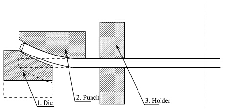
2 Analysis of JCOE forming process 2.1 JCOE forming process 2.1.1 Crimping forming processThe punch and sheet in crimping process were usually fixed. Firstly, the sheet was clamped by two holders and the die in crimping process rose gradually. Then, the sheet edge was bended little by little starting from point O along the shape of the punch. With the sheet forming, the curvature of the sheet edge increased and the arm of force was shortened. The sheet began unloading and springback happened when die reached the setting displacement (see Fig. 1).
|
| Fig. 1 Crimping forming process |
The JCO forming is a progressive multi-step air bending process, in which every air bending is a three point bending forming process. On average, an odd number of times (N) operations are needed. First, the plate entered the JCO forming machines and then it was formed into "J" shape by (N -1)/2 times bending in Fig. 2a. Afterwards the other side of the plate was gradually sent into the JCO forming machines by feeding mechanism. Another half of the steel plate was bent into a "C" shape by (N -1)/2 times step as well as in Fig. 2b. At last, the sheet was pressed into open "O" shape in Fig. 2c. According to the mode of forces, the JCO bending mode can be divided into unsymmetrical bending and symmetrical bending. Because of unsymmetrical contact condition between sheet and die, it is called unsymmetrical bending in (N -1) steps. At last, symmetrical bending conditions leaded to symmetrical bending.

|
| Fig. 2 JCO forming process |
Calibration, as the last forming process of welding pipe, is achieved through mechanical expanding of steel tube (see Fig. 3). The hydraulic cylinder piston drives the pull rod and spindle moves to the left. Internal mandrel extends outward, which makes welding pipe expanding.

|
| Fig. 3 Principle of mechanical expanding |
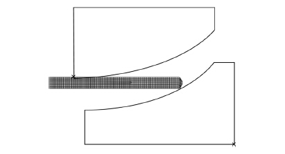
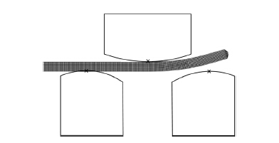
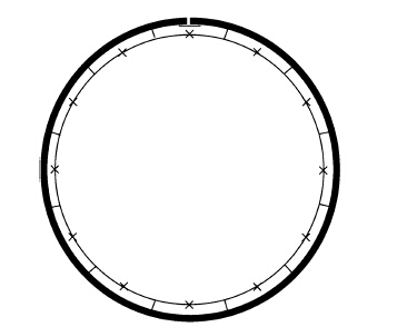
FEA was carried out using the commercial code ABAQUS/ Standard. Because of wide sheet bending, a two-dimen-sional FE model was established for the plane strain con-dition. Figures 4-6 show the set-up of the FEM model.
|
| Fig. 4 Geometric model of crimping |
|
| Fig. 5 Geometric model of JCO forming |
|
| Fig. 6 Geometric model of expanding |
The FE model convergence was amended by reducing minimum iteration and improving contact state stability.Also, simple limited slid master-slave contact algorithm was selected, in which the mould was master surface, the sheet was slave surface, and the penalty function model of friction coefficient 0.1 was established to judge the con-tacting state. This model allowed the elastic slid and the sheet surface to be invaded by mould, which did not increase the system degrees of freedom and the computa-tional efficiency was greatly improved.
In metal forming simulation, Considering both effi-ciency and accuracy in the deformation process, the 2 mm four-node plane strain reduced integration quadrilateral element CPE4R was set in deformable sheet. The sheet metal was defined as elastic-plastic. The crimping set was composed of the die, punch and sheet. The discrete rigid body and 2.5 mm R2D2 element were defined in punch and die without considering the deformation.
The moulds (punch and die in JCO forming, spindle in expanding) are defined as analytical rigid. The analytical rigid does not need requiring elements but it is only used in simple geometric shapes.
Blank material has been modelled as elastic/plastic. Elastic properties are necessary for spring-back calculation, while an isotropic hardening (Von Mises yield criterion) has been adopted for the simulation of the plastic behaviour.
The numerical analysis of the forming phase has been divided into seven steps: (i) blank clamping and crimping tools positioning; (ii) border deformation by crimping die; (iii) crimping tools removal and JCO forming tools acti- vation; (iv) multi-step air bending by punch motion; (v) welding is replaced by displacement constraint; (vi) JCO forming tools removal and expanding tools activation; (vii) expanding deformation and springback by expanding tools.
The objectives of this analysis are to investigate the deformation characteristics of JCOE forming. Also this analysis is used to optimize process parameters for improving quality of welding pipe.
2.3 ExperimentThe sheet metal used in experiments was Q235A, with its basic mechanical properties, as listed in Table 1. Here, E and rs denote the Young’s modulus and tensile yield stress, respectively. n is the power-law strain hardening exponent and K the strength coefficient.
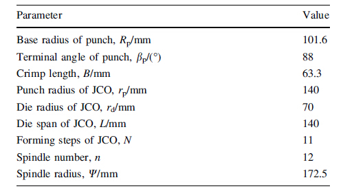
All of the moulds used in the experiment were shrunk size of the actual production mould; their geometric parameters are listed in Table 2.
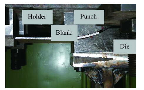
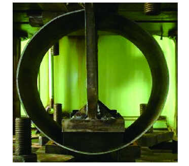
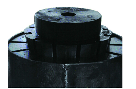
The experiments were performed in a 3 150 kN hydraulic press, which is normally used for the try-outs of production tools. The press was equipped with sensors for measuring the punch force. All sensors were connected to a PC system. Figures 7-9 show the tool in the press in the JCO forming experiment. The shapes of welding pipe before and after springback were measured using a portable three-coordinate measuring system. The estimated measurement error was 0.02 mm.
|
| Fig. 7 Photograph of crimping experiment |
|
| Fig. 8 Photograph of JCO experiment |
|
| Fig. 9 Photograph of mechanical expanding experiment |
In this study, two key indicators included ovality u and average radius deviation DG can be defined. The average radius deviation is used to measure how close welding pipe gets to round.
where Rmax, Rmin and Rm are the maximum radius, the 1 minimum radius and average radius, respectively. Ri is the radius at bending point.
Seven experiments were performed on the Q235A metal in order to validate the FE model. The deformation of sheet in JCOE forming could be adjusted by controlling the displacement of moulds.
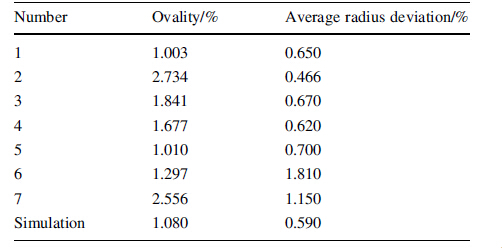
The results of JCOE experiments are put together to validate FE model. Tables 3 and 4 show the comparison between experimental results and FEA.
From Table 3 five of the seven groups experimental results of ovality experimental values are greater than the simulation value and the maximum absolute error is 1.476%. Six of the seven groups experimental results of average radius deviation values are greater than the simu-lation value, and the maximum absolute error is 1.22%.
Table 4 shows that the maximum absolute error of ovality is 0.15% and the maximum absolute error of average radius deviation is 0.22%.
Numerical simulation errors come from the insta-ble material and CAE model simplification. The numerical simulation results coincide well with experimental results, which verify the accuracy of the model.
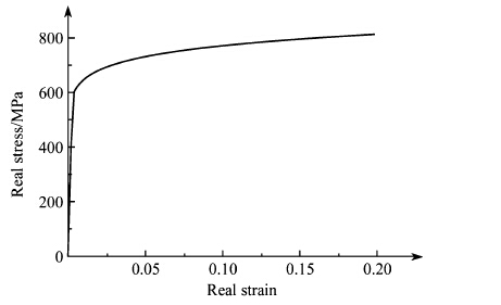
3 Results and discussionsThe capability of the model will be demonstrated using a "base case" example, consisting of a 1 219 mm pipe with a wall thickness of 22 mm and the mechanical properties shown in Fig. 10 has been used, based on the results obtained performing standard tensile tests on some specimens cut by the blank.
|
| Fig. 10 X80 material characteristics |
Figure 11 shows the geometry shape of crimping forming after unloading. The undeformed section is defined as length straight edge Lz which determines the shape of welding joint. The curvature of deformed section is evaluated by the equivalent radius of curvature R’:
where αy is the bending angle after springback.
In the term of residual stress distribution, which depends on springback in sheet metal forming which is the reverse elastic deformation during the process of unloading process. And the residual stress can be solved by the vector superposition of load stress and reverse elastic stress in springback. So, from Fig. 11, it is known that the residual stress of the crimping is mainly con-centrated on both sides of neutral layer and the maxi-mum residual stress is 427 MPa. In same time, it is demonstrated that the springback includes not only elastic unloading, but also local loading, which affects the dimensional accuracy and distribution of residual stress in crimping.

|
| Fig. 11 Mises stress of crimping unload |
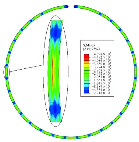
The welded pipe after crimping and JCO forming is in the shape of bamboo segment (see Fig. 12). In addition, the residual stress after the first bending of both sides in JCO forming is overlapping. But the rest bending in JCO forming has a pretty clear dividing line with distribution of residual stress due to step by step bending. The step S can be calculated
|
| Fig. 12 Stress distribution after JCO forming process |
where Ck is the width of blank.
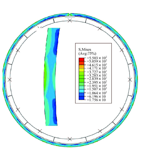
The mechanical expanding is equal to reverse bending. So, the deformation characters after mechanical expanding became vaguer (see Fig. 13). The results indicate that mechanical expanding can make residual stress homoge-nization and the maximum value of residual stress reduces about 100 MPa, and the highest reduction ratio was 60.22%.
|
| Fig. 13 Stress distribution after expanding |
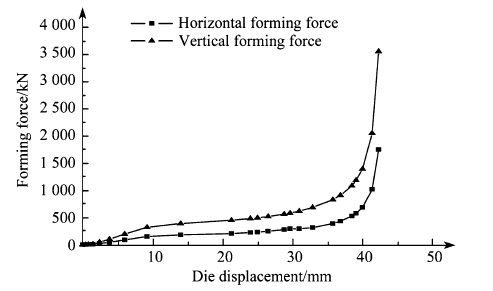
The relationships of forming forces and die displacement in crimping process are shown in Fig. 14. Overall, the direction of forming force is the same with bending angle in the crimping process. The vertical forming force is greater than the horizontal forming force since crimping bending angle is less than 45°. Firstly, the forming force and displacement is linear at elastic deformation, in which the elastic deformation plays a major role. Then the forming force increases slowly because the material begins to yield and the hardening behavior affects the forming force. At last, the forming force increases significantly at die displacement of 40 mm for the length of force arm decreasing.
|
| Fig. 14 Relationships between forming forces and die displacement in the crimping process |
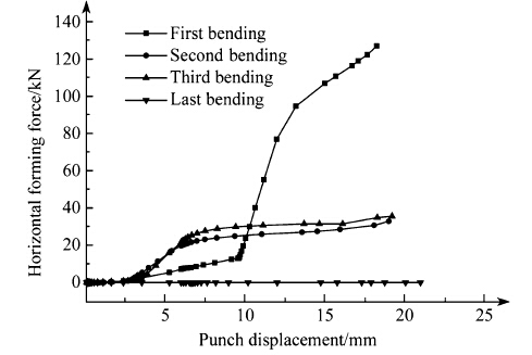
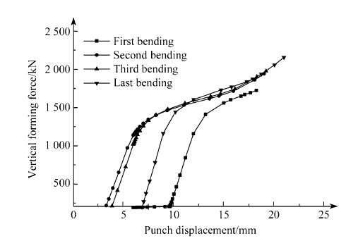
In this paper, the effects of forming force in typical three initial bending and last bending of JCO forming were studied.
As illustrated in Figs. 15 and 16, rigid body rotation of the sheet occurs because of unsymmetric bending in first stage of bending. The forming force linear changes when the sheet metal begins deformation in second stage. With material of sheet gradually enters into the yield stage, the forming force growth slows.
|
| Fig. 15 Relationships between horizontal force and punch displacement in JCO asymmetry bending forming |
|
| Fig. 16 Relationships between vertical force and punch displacement in JCO asymmetry bending forming |
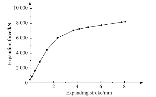
The expanding force increases with expanding stroke in mechanical expanding process as shown in Fig. 17. Similar to the bending deformation, the forming force linear changes in initial stage. With material of sheet gradually enters into the yield stage, the forming force growth slows.
|
| Fig. 17 Relationship between expanding force and displacement in mechanic expanding |
At present, it could be blind to design JCOE forming process parameters according to the research results. In same time, each step of the JCOE process has variables that influence the shape of the finished pipe. In an effort to quantify the influence of such parameters on pipe shape performance, the JCOE forming processes under different processing conditions are calculated with the validated FE model, and the influences of these parameters including vertical forming force in crimping, number of bending in JCO forming and expanding ratio in mechanical expanding on the forming quality indicators.
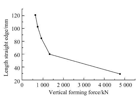
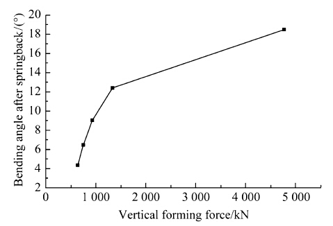
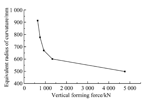
In crimping, the relationships between crimping quality indicators including bending angle after springback, equivalent radius of curvature and length straight edge and the vertical forming force (see Figs. 18-20). In Fig. 18, the bending angle after springback in crimping increases monotonically with the vertical forming force. In Figs. 19 and Figs. 20, the equivalent radius of curvature and length straight edge decreases monotonically with the increase of the vertical forming force. And crimping deformation effect is not obvious when greater than 1 500 kN from Figs. 18-20. Thus, it is not possible with just adjusting vertical forming force to shorten length straight edge for improving forming quality effectively.
|
| Fig. 18 Relationship between length straight edge and vertical forming force in crimping |
|
| Fig. 19 Relationship between bending angle after springback and vertical forming force in crimping |
|
| Fig. 20 Relationships between the average deviation of radius and number of bending in JCO forming |
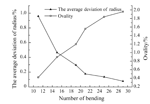
In JCO forming, the relationships between JCO forming quality indicators including the ovality and the average deviation of radius and the number of bending are inves-tigated (see Fig. 21). From Fig. 21, the tendency of ovality is opposite to the average deviation of radius. The ovality after JCO forming increases monotonically with the num-ber of bending. The increase of overlapping deformation area leads to the unstable springback and increased ovality. When the edge number of polygon welded pipe increases, the geometry characteristic of weld pipe tends to circle. The average deviation of radius decreases monotonically with the increase of the number of bending.
|
| Fig. 21 Relationships between the average deviation of radius and number of bending in JCO forming |
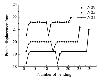
In order to obtain qualified weld pipe, the displacement of bending must be matched with the number of bending. The relationship is displayed in Fig. 22. The punch displacement decreases with the increase of the number of bending.
|
| Fig. 22 Relationships between punch displacement and number of bending in JCO forming |
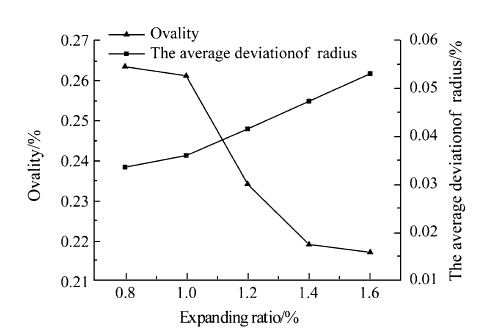
In mechanic expanding forming, the relationships between mechanic expanding forming quality indicator and the number of bending is shown in Fig. 23. In Fig. 23, the ovality after mechanical expanding forming increases monotonically with the expanding ratio. The study shows that the elastic deformation of material can be ignored because of the dominance of plastic deformation. The shape of welded pipe is calibrated effectively in the mechanic expanding stage. The average deviation of radius decreases monotonically with the increase of the expanding ratio since too large local deformation leads to increase springback and significant Bauschinger effect. Thus, the right expanding ratio must be found to keep a balance.
|
| Fig. 23 Relationship between ovality and expanding ratio in mechanic expanding |
In this study, a FE model for the whole JCOE pipe forming process is established. The deformation behaviors of an X80 plate in all the JCOE forming stages are numerically analyzed. A parametric study of JCOE forming is per-formed to assess the effects of the key process forming parameters on pipe geometrical shape. The following conclusions can be drawn.
(i) The simulated configuration of plate in each forming stage shows good agreement with the practical measurement. The FE model can predict geometry shape of welded pipe very well.
(ii) The shape of welded pipe after crimping and JCO forming looks like bamboo segment and the residual stress is uneven and concentrated. But the mechanical expanding can greatly reduce residual stress and improve the stress distribution mode. So, the mechanical expanding is key forming process, which can not only calibrate the shape of pipe after JCO forming but also make the distribution of residual stress more uniform than that in previous forming steps.
(iii) Proper vertical forming force in crimping can lead to a favorable crimping curvature and alleviate length straight edge defect. From the parameter study of JCO forming section, it can effectively reduce the ovality by means of decreasing the numbers of bending in JCO forming, but may lead to some new problems, such as producing out-of-tolerance in the average deviation of radius, a balance must be found. In terms of influence of expanding forming, expansion plays a significant role in avoiding ovality defect. A smaller ovality can be obtained by increasing expanding ratio, but excessive increment in expanding ratio should be avoided, which can lead to rapid increase of the difficulty of forming.
Acknowledgments The authors are grateful for the financial support provided by the Natural Science Foundation of Hebei Provincial Education Department, China, the Natural Science Foundation of Inner Mongolia, China, the Inner Mongolia Higher School Science and Technology Research Projects and the Program of Higher-Level Talents of Inner Mongolia University, China.| 1. | Zhao J, Li J, Qu XY, et al(2011) Study on intelligent control technology for forming steel pipe of pipeline with JCO process. Sci China Technol Sci, 54(10), 2754-2759 doi:10.1007/s11431-011-4532-8 |
| 2. | Zhao J, Sun H, Li J, et al(2011) Four point bending JCOC process:a new technology for forming longitudinally submerged arc welding pipe. J Plast Eng, 19(6), 59-62 |
| 3. | Zhao SY (2010) Study on quality control strategy and simulation system development of UOE pipe forming. Dissertation, Yanshan University |
| 4. | Giannoula C, Spyros AK, George EV(2016) Finite element analysis of UOE manufacturing process and its effect on mechanical behavior of offshore pipes. Int J Solid Struct, 83, 13-27 doi:10.1016/j.ijsolstr.2015.12.020 |
| 5. | Zou T, Wu G, Li D, et al(2015) A numerical method for predicting O-forming gap in UOE pipe manufacturing. Int J Mech Sci, 98, 39-58 doi:10.1016/j.ijmecsci.2015.04.006 |
| 6. | Palumbo G, Tricarico L(2005) Effect of forming and calibration operations on the final shape of large diameter welded tubes. J Mater Process Technol, 164-165(5), 1089-1098 |
| 7. | Liu J, Huang K, Ruan F(2005) Effects of the parameters of prebending on O-forming of pipe in UOE process. J Plast Eng, 12(3), 72-75 |
| 8. | Herynk MD, Kyriakides S, Onoufriou A, et al(2007) Effects of the UOE/UOC pipe manufacturing processes on pipe collapse pressure. Int J Mech Sci, 49(5), 533-553 doi:10.1016/j.ijmecsci.2006.10.001 |
| 9. | Hong L(2006) Prebending process of longitudinal submerged arc welding production line. Welded Pipe Tube, 29(1), 55-57 |
| 10. | Xie Z, Xia J(2007) Pre-bending process parameter design of longitudinal submerged arc welding pipe. Welded Pipe Tube, 30(3), 52-54 |
| 11. | Yin J, Zhao J, Qu XY, et al(2011) Springback analysis of expanding and setting round for large diameter pipe. J Mech Eng, 47(12), 32-42 doi:10.3901/JME.2011.12.032 |
| 12. | Fan LF, Gao Y, Li Q, et al(2011) Research process of mechanical expanding for large diameter pipe. Heavy Mach, 5, 1-5 |
| 13. | Fan LF, Gao Y, Li Q, et al(2012) Quality control on crimping of large diameter welding pipe. Chin J Mech Eng, 25(6), 1264-1273 doi:10.3901/CJME.2012.06.1264 |
| 14. | Ma HK, Li PL, Sui J, et al(2014) Theoretical and finite element analysis for JCOE pre-bending forming process. Process Equip Pip, 51(3), 65-69 |
| 15. | Guo BF (2001) FEM simulation and experimental study on mechanical expanding process of linepipeI. Dissertation, Yanshan University |
| 16. | Fan LF (2012) Effect of JCOE forming technical parameters on welding quality. Dissertation, Yanshan University |
| 17. | Fan LF, Gao Y, Yun JB, et al(2015) Multi-objective optimization of crimping of large-diameter welding pipe. J Cent South Univ, 22, 2540-2548 doi:10.1007/s11771-015-2783-4 |
| 18. | Fan LF, Gao Y, Yun JB, et al(2015) Robustness design for crimping of large diameter straight welded pipe. China Mech Eng, 26(8), 1112-1116 |
| 19. | Gao Y (2011) Study on theory and computer simulation of JCO forming for large diameter longitudinal welding pipe. Yanshan University |
| 20. | Yan JX, Fan LF, Yun JB(2015) Stochastic analysis of crimping quality for straight welding pipe. Mech Sci Technol Aerosp Eng, 34(12), 1880-1884 |
| 21. | Tong X (2008) Study on groove shape and the open angle of end tab of UOE pipe. Dissertation, Yanshan University |
| 22. | Gao Y, Li Q, Fan L(2010) Finite element analysis of JCO forming process for longitudinal seam submerged arc welded pipes. J Model Identif Control, 11(3/4), 239-249 doi:10.1504/IJMIC.2010.037036 |
| 23. | Ren Q, Li DY, Zhou TX, et al(2011) The simulation of UOE pipe forming by three-dimensional finite element method. J Netshape Form Eng, 3(6), 80-84 |
| 24. | Yang Q (2012) Springback analytic and process parameters optimization of plate edge preflex for the forming of large diameter longitudinal seam welded pipe. Dissertation, Yanshan University |
 2016, Vol. 4


