 2016, Vol. 4
The article information
- Mehdi Moayyedian, Kazem Abhary, Romeo Marian
- Gate design and filling process analysis of the cavity in injection molding process
- Advances in Manufacturing, 2016, 4(2): 123-133
- http://dx.doi.org/10.1007/s40436-016-0138-5
-
Article history
- Received: 2015-06-28
- Accepted: 2016-03-28
- Published online: 2016-05-09


The 20th century has witnessed,the rapid increase of plastics and their intrusion into all markets have been observed [1]. According to the world consumption of raw materials by weight,plastic is the highest in comparison with other raw materials such as aluminum,steel,rubber,copper,and zinc. This is due to the specific properties and less production cost [2]. One of the most significant pro cesses in manufacturing of plastic products is injection molding. Approximately one-third of all plastics are con verted into parts via injection molding [3, 4]. The injection molding process is growing significantly in many industries like packaging,aerospace and aviation,building and con struction,automotive parts,household articles,and so on [5]. The quality of the injection moldings depends on the material characteristics,mold design and the process con ditions [6]. Three fundamental operations in injection molding consist of the conversion of plastic granules into a melt,the injection of molten plastic into cavities and finally the ejection of the part from the cavities via opening the mold tools [7, 8].
One of the factors which determines the final quality of final part is the geometry and size of the gate [9]. The main purposes of the gate are: (i) to transfer the molten plastic into the cavities,(ii) to have a control over the melt flow both in filling and packing stages,(iii) to freeze the poly mer at the end of injection which leads to the withdrawal of the screw [10]. In addition,the gate has significant effect on the performance of final product [11]. The gate directly controls the flow process in the cavity which determines the appearance of the injected part [12]. The size and geometry of gate will affect the mechanical properties and dimensional stability of the injected part [13]. Different rules will be evaluated for gate system such as smaller gate size to minimize the scrap,easier ejection from mold tools and de-gating,central flow stream of gate with runner system to reduce the internal and external defects [14].
Ten common gates are represented in Fig. 1 [15]. After the evaluation of different geometries for gate system,a modified edge gate is evaluated as an effective geometry of gate system which will be discussed in the following sections. The initial intention is to design a gate with new geometry described in this paper for the following reasons: (i) easier de-gating of the injected part with less visible blemish; (ii) improving the defect reduction such as flashes and sink marks; (iii) better contact surface between gate and the injected part; (iv) no short shot defects for the injected part with new design of gate system.
 |
| Fig. 1 Ten common types of gates used in injection molding |
The Taguchi method is a comprehensive quality strategy that conducts minimal number of experiments using orthogonal array and forms robustness into a process during its design stage [16, 17, 18]. The quality of injected part which is affected by many parameters and the number of these variables is high,that is why the studying task which is required to perform by computer aided engineering (CAE) can be remarkable. Hence,design of experiment (DOE) is an acceptable method to reduce the number of numerical experiments and obtain enough information which is used in real experiments [18]. Taguchi is a technique to predict the significant and insignificant variables and the optimum level of the design variables by running a series of experiments.
Taguchi has three main stages which are system design,parameter design and tolerance design. In system design,the target is to use the scientific and engineering information to produce the parts. In tolerance design,the key point is to evaluate and analyze the tolerances for optimum combination of process parameters. To determine the optimum levels of process parameters,parameter design is significant [17]. In this study,parameter design is joined to attain the optimum levels of process parameters which lead to a reduction of scrap rate during the production of thinshell plastic part.
To evaluate the effects of a number of factors all together,the orthogonal array to organize matrix experiments is an effective tool [19]. Based on the selected orthogonal array,Taguchi technique will reduce the number of experiments,which leads to a reduction in time and cost. This special design of orthogonal array will cover the whole parameters with a small number of experiments,allocate control parameters and design variables to the columns of an array,and transfer the integers in the array columns into the real setting of parameters [17, 20]. Taguchi method proposes signal to noise (S/N) ratio to determine the quality characteristics considered for any problems in engineering design. S/N ratio has three phases: smaller the better,the nominal the best,and the larger the better [17]. In this study,the smaller the better quality characteristic is selected to reduce the scrap rate through the optimal level of each process and geometric parameters. Analysis of variance (ANOVA) will be applied to evaluate the effect rate of process and geometric parameters on scrap rate for an injected part. Hence,the optimum level of each parameter will be determined.
The contribution of this paper is the new design of gate system of the injection molding. It leads to easy de-gating of the inject part,better attachment with part geometry and part specifications and reduction of the internal defects such as sink marks with the replacement of modified edge gate with current edge gate. In this paper,the structure of modified edge gate is introduced. The calculation of modified edge gate is implemented based on the size and geometry of the injected parts. Then the design of feeding system and injected part for two different gates is conducted via SolidWorks. To have an accurate result of simulation,finite element method (FEM) is considered via SolidWorks plastic. Finally,to validate the model,the experiments have been conducted for two injected parts.
1.2 Experimental set upThe selected parts for the injection are two circular plates with 100 mm diameter and 1 mm thickness. For manufacturing mold tools,different machines such as drilling,milling,and grinding are taken into consideration for different components of the mold tools. The selected material for the injection is polypropylene (PP) and the injection machine for data collection is Poolad-Bch series.
2 Methodology 2.1 Improved edge gateThe gate or the initial entry point of molten plastic into the cavities is a significant component for engineers to evaluate. It should be as small as possible to avoid the excess material removal and a visible blemish on the part [21]. The most basic type of the gate is current edge gate which has the rectangular cross section. The main advantage of an edge gate is to use for multi cavity molds [22]. Generally,the cross section of the gate is very important to de-gate of the injected part with less visible blemish,which has better attachment with part geometry and a smooth entrance of molten plastic into the cavities. Modified edge gate will satisfy all these conditions of an acceptable gate.
2.2 Cross sectional shape of an improved edge gateThe main purpose of the gate is to transfer the molten plastic from runner to the cavities. The most basic type of the gate is an edge gate which has rectangular cross section. As shown in Fig. 2,modified edge gate has an elliptical cross section and an edge gate has a rectangular cross section. Filling process of an improved edge gate is different from that of the current edge gate. It has resulted from a smooth entrance of molten plastic into the cavities by removing the corners of an edge gate. In addition,degating of an improved edge gate is easier than that of the current edge gate which results from the replacement of elliptical cross section of improved edge gate with sharp corners of the rectangular cross section of current edge gate.
 |
| Fig. 2 |
The first step is to calculate the gate dimension for current edge gate with rectangular cross section for each cavity which has 1 mm thickness and 100 mm diameter. The reason to have injected parts with these dimensions is to eliminate any defects in a critical condition so that it is feasible to apply the new cross section for any thickness. The selected geometry is two flat circular parts to insure that there are no other parameters like sharp corners in rectangular or square geometry,and bosses in complex geometry which affect the final evaluation. Hence,the determination of gate dimension for current edge gate is calculated via Eqs. (1) and (2).
where w is the width of the gate,a the total surface area of the injected parts in mm2,and n a material constant. For different applications,this method provides a reasonable result for gate size.

where h is the height of the gate,t the thickness of the injected part in mm. The runner and gate length in total is 280 mm for two circular parts. The sprue is of 60 mm length and 1.5° draft angle.
The selected material for this calculation is PP.

Finally,the width and height of the rectangular cross section according to Eqs. (1) and (2) are 2.06 mm and 0.7 mm,respectively (see Eqs. (3) and (4)). Hence,for an improved edge gate,the major axis is 2.06 mm and minor axis is 0.7 mm as shown in Fig. 2.
2.4 Selection of the factors,factor levels and orthogonal array 2.4.1 Selection of the factorsFive factors were selected which are filling time,part cooling time,pressure holding time,melt temperature,and gate type.
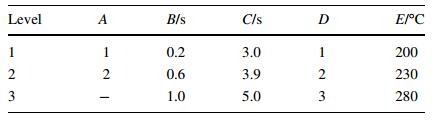
2.4.2 Selection of the factor levelsThere are three levels of each selected factors using Taguchi method. The reason for selecting three levels (low,medium,high) instead of two levels (low,high) is that three levels of each factor will give more accurate results in comparison with two levels of each factor. The selected factors are gate type (A),filling time (B),part cooling time (C),pressure holding time (D),and mold temperature (E).
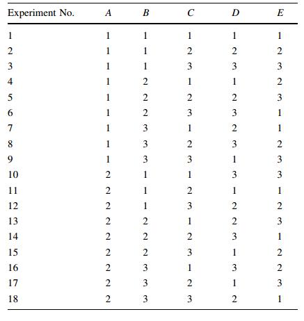
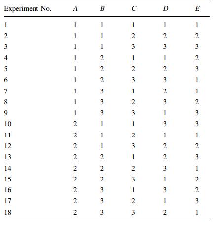
2.4.3 Selection of orthogonal arrayAccording to the number of parameters and levels chosen,L18 orthogonal array was shown in Table 1.
The S/N ratio applies the average values to convert the experimental result into the value which is feasible for the evaluation characteristic of an optimum parameter analysis. Since the objective of this study is to reduce the scrap in injection molding via optimum parameters,the smaller the better quality characteristic has been reflected which is defined as follows.
The mean square deviation (MSD) for the smaller the better quality characteristic can be stated by Eq. (5) [20]:
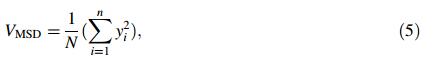
where yi is the value of scrap rate and N is the total number of data points. The proposed method is to calculate scrap rate which is equal to the ratio of approved parts to the rejected part.
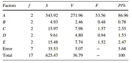
2.6 ANOVAANOVA will compute the quantities such as degree of freedom (f),sum of squares (S),variance (V),F-ratio (F),and percentage contribution (P). Finally,ANOVA will determine the contribution percentage of selected factors in regards to scrap rates evaluation.
3 SimulationsAfter designing two circular parts as two samples for this application,the next step is to simulate the part via SolidWorks plastic. For simulation,defining the injection system is necessary. Hence,designing the sprue,runner and gate system with consideration of prior calculations should be obtained (see Fig. 3).
 |
| Fig. 3 Samples of injection with sprue, runner and gate system |
To ensure that the analysis results are sufficiently accurate,FEM plays a significant role in simulation. According to the geometry of samples,the triangle mesh for finite element analysis is shown in Fig. 4. The selected material for this simulation is PP. Different sizes are evaluated for the triangle surface mesh from different mesh sizes,finally size of 1 mm is chosen for the injected part and smaller size is chosen for the injection system which consists of sprue,runner and gate. It is resulted from the sensitivity of injection system as a critical area of this simulation. Hence,triangle of size 0.3 mm for sprue and runner and triangle size 0.2 mm for gate are selected for both elliptical and rectangular cross sectional shapes of edge gate. The accuracy of the mesh is determined through a mesh refinement study.
 |
| Fig. 4 Finite element analysis for an improved edge gate |
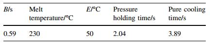
The next stage is to set up appropriate process parameters. According to the selected materials and injection machine for this simulation,filling time is 0.59 s,melt temperature 230 ℃,mold temperature 50 ℃,pressure holding time 2.04 s,and pure cooling time 3.89 s. As mentioned before,the geometry and size of the injection system are the elements affecting the operation cycle time,cooling time,defects such as sink marks and short shot. After running the simulation,the main factors to check if the improved edge gate is acceptable in terms of new geometry and size,are ease of fill with no short shot,filling time analysis,sink marks analysis,and injection pressure at the end of filling. As shown in Fig. 5,ease of fill for an improved edge gate is the green area which is in the most satisfactory level. It means that there is no short shot for the injected parts.
 |
| Fig. 5 Easy filling of injected part with an improved edge gate |
Filling time is another factor to ensure that by proposing the modified edge gate as a replacement of current edge gate the filling time will not increase. Based on the simulation via SolidWorks plastic,there is no difference of filling time between current edge gate and modified edge gate. Hence,the modified edge gate does not impede to apply in mass production,as shown in Fig. 6.
 |
| Fig. 6 Filling time |
The final quality of the injected part is critically significant in plastic industry. One of the common defects is related to gate and runner dimension,and the geometry is sink mark. Sink mark is the depression on the surface of the injection molded plastic which happens during the plastic cooling process [21]. As shown in Fig. 7,there is a level of sink mark on the side surface of injected part with current edge gate. But with modified edge gate there is no sink mark on the side surface of final part which results from lower turbulence of molten plastic into the cavities by removing the sharp corners of the current edge gate.
 |
| Fig. 7 Sink mark simulation a for edge gate b for modified edge gate |
Shear rate and shear stress are two main factors which will change the final quality of the injected part and will be evaluated as internal defects in injection molding. The shear rate in gate is the highest in comparison with runner and cavity. Thus,local flow rate and shear rate continuously change during the filling stage of injection molding process based on that the channel depth and the cross section are of flow [2]. The shear rate and the shear stress analysis for the current edge gate and modified edge gate are evaluated and determined via SolidWorks plastic,as shown in Figs. 8 and 9,respectively.
 |
| Fig. 8 Shear rate analyses for |
 |
| Fig. 9 Shear stress analyses for |
It is clear that the corners of current edge gate will increase the turbulence of molten plastic. The turbulence of molten plastic leads to an increase in shear rate,shear stress and finally reduction in mechanical properties of the final injected parts. The modified edge gate has a smooth motion of molten plastic into the cavities with the minimum shear stress of the injected part.
Another factor to evaluate is the flow velocity distribution for both gates to make sure that the molten plastic has a robust flow into the cavities. As shown in Fig. 10,the flow velocity distributions for current and modified edge gates are 15.055 6 cm/s and 27.646 5 cm/s,respectively,and have a defined direction. It is acceptable that in modified edge gate by removing the sharp corner of current edge gate,the size of the gate becomes smaller and the velocity of molten plastic into the cavities is increased.
 |
| Fig. 10 Flow velocity distribution for |
Another evaluation is the packing pressure near gate and also far away from the gate for both gate systems. The exertion of pressure on the cavity during the packing stage is controlled by the reciprocating screw. It is clear that the speed of molten plastic in modified edge gate is higher than that of in current edge gate. Based on the equal filling time for both gate systems,the packing pressure at the end of the filling for modified edge gate does not affect the injected part,but for the current edge gate the packing pressure at the end of filling is higher for the cavities to fill the cavities properly (see Fig. 11). Higher packing pressure will damage the injection machine and lead to different plastic defects such as flashes which will evaluate in experimental parts.
 |
| Fig. 11 Packing pressure at the end of filling for a current edge gate and b modified edge gate |
One of the parameters which evaluate the possibility of short shot for both gates is the maximum inlet pressure. By increasing the maximum inlet pressure,the sort shot possibility will increase. The selected samples have critical condition which results from 1 mm wall thickness. According to the simulation and experiments,this part can be successfully filled with injection pressure 46.3 MPa and clamp force of 20.23 t. The injection pressure is less than the maximum injection pressure limit which is satisfactory (see Fig. 12). Hence,the possibility of short shot for the injected parts is low. The injection pressure for current edge gate is 44.85 MPa and clamp force of 19.98 t which is satisfactory and close to proposed edge gate.
 |
| Fig. 12 Injection pressure limit for edge and improved edge gate |
Based on different applications,different concepts in manufacturing of mold tools are allocated such as twoplate,three-plate,etc. According to the geometry of the injected part and the feeding system which includes the runner and gate geometry,two-plate mold with two cavities without ejector pin is manufactured with steel CK45 with surface hardness 56 HRC. The manufacturing of two modified edge gates for two cavities is conducted (see Fig. 13).
 |
| Fig. 13 Cavity plate with modified edge gate and cooling channel a before grinding; b final cavity plate after grinding |
To make sure that other factors do not affect the final quality of the injected part,setting the process parameters at the right level is essential. Based on the selected geometry for the injected part,injected material,injection machine,simulation advice,and human expert,5 different parameters need to be set at right level which are filling time,melt temperature,mold temperature,pressure holding time,and pure cooling time (see Table 2).
The evaluation of modified edge gate in comparison with current edge gate after setting up the mold tools and injection machine is the target of this experiment. Different analyses related to gate selection are applied such as short shot analysis that relates to the size of the gate and internal defects such as sink marks. Hence,two cavities with modified edge gate filled properly and there is no short shot defect for the modified edge gate. The results from the appearance of different samples demonstrate that there are no flashes for the injected part with modified edge gate. Gates and runners with sharp corners are not the right choices. They lead to different stresses near the gate or the conjunction of gate and the injected parts [2]. It is obvious that the modified edge gate does not have any sharp corners in comparison with current edge gate. It has a central flow with runner system which all together leads to a robust flow of molten plastic into the cavities to reduce the scrap of final injected parts. The injected parts with modified edge gate are evaluated in right levels,as shown in Fig. 14. Hence,no short shot or flashes are detected in different samples. In addition,based on the new design,it is obvious that the contact area of modified edge gate which has elliptical cross section is smaller than that of current edge gate which leads to less visible blemishes and finally less scrap rates. As shown in Fig. 15,the injected parts with current edge gate have flashes at the end of the injected parts.
 |
| Fig. 14 Injected parts with modified edge gate in right level of each parameter |
 |
| Fig. 15 Injected part with current edge gate in right levels of each parameter |
To determine the scrap rate of the injected parts,the mold tools with both current edge gate and modified edge gate will be considered for the injection process. Taguchi method which includes selection of orthogonal array,S/N ratio,and ANOVA,will be applied to determine the significant factors in scrap evaluation.
4.4.1 Selection of factorsBased on two design features of gate and the process parameters,the selected factors are shown in Table 3.
According to the number of parameters and levels which have been chosen,L18 orthogonal array is considered as shown in Table 4.
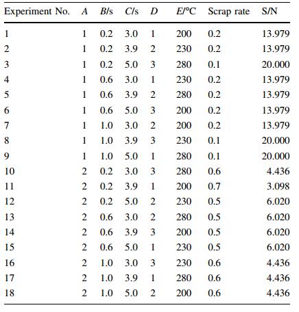
The smaller the ratio the better is the objective of this study. The calculated results for scrap rate and S/N ratio have been determined in Table 5.
From the data in Table 5,the average S/N ratio for response table can be calculated (see Table 6) to determine the optimal levels of four process parameters and one geometric parameter.

From Table 6,it can be seen that the larger value of |DT| demonstrates the significance of each parameter which increases the visible blemishes of injected part and finally the scrap rate. Although other parameters have the minimum contributions in increasing the scrap rate,the optimum set of parameters can be evaluated from Table 6 by selecting the highest level of S/N for each parameter. The result is a combination ofA(level 1),B(level 3),C(level 3),D(level 2),and E(level 3) to have minimal scrap rate.
4.4.4 ANOVAThe scrap rate in Table 5 was analyzed via ANOVA and the significance rate of factors was evaluated by percentage (P) as shown in Table 7. The percentage weigh of gate type was the most influential factor with a contribution of 86.96%. The contribution of filling time,part cooling time,pressure holding time and melt temperature is very low in comparison with gate type.
Based on the orthogonal array (L18),for each trial number,10 samples were injected and the scrap rates for 18 trial numbers were determined (see Table 5). Total 180 samples were injected for two different gates in different conditions. Trial numbers 1 to 9 are for modified edge gate and 10 to 18 are for current edge gate. The scrap rate for 180 parts was evaluated as shown in Fig. 16. There is 17% scrap rate for modified edge gate and 56% scrap rate for current edge gate. It is clear that the final cost of the injected parts is a proportion of the scrap rate. Hence,the efficiency of modified edge gate is higher than that of current edge gate.
 |
| Fig. 16 Scrap rate for both modified and current edge gate |
The significant reasons of internal defects in the injection molding are the wrong size and geometry of the runner and gate system. Gate system is the first orifice in mold design which leads to the injection of molten plastic into the cavities. Gate system has different designs for different applications. A modified edge gate and current edge gate were successfully developed via simulation with SolidWorks plastic for two circular plates with thickness of 1 mm.
For model validation,experimental tests were implemented. The simulation results were very close to the experimental ones showing that the modified edge gate in comparison with current edge gate has less turbulences of molten plastic into the cavities. It leads to the reduction of internal and external defects of the injected parts. Easier de-gating of modified edge gate in comparison with current edge gate has less visible blemish of the part which leads to the scrap reduction of final injected parts. The percentage weigh of gate type was the most influential factor with a contribution of 86.96%. There is 17% scrap rate for modified edge gate and 56% scrap rate for current edge gate. Finally,by the modified edge gate,the optimum set of process parameters to have the minimum scrap rate is A(level 1),B(level 3),C(level 3),D(level 2),and E(level 3).
| 1. | Salimi A et al (2013) Prediction of flow length in injection molding for engineering plastics by fuzzy logic under different processing conditions. Iran Polym J 22(1):33-41 |
| 2. | Zhou H (2012) Computer modeling for injection molding:simulation, optimization, and control. Wiley, Hoboken |
| 3. | Tang SH, Kong YM, Sapuan SM et al (2006) Design and thermal analysis of plastic injection mould. J Mater Process Technol 171(2):259-267 |
| 4. | Pirc N, Schmidt F, Mongeau M et al (2009) Optimization of 3D cooling channels in injection molding using DRBEM and model reduction. Int J Mater Form 2(5):271-274 |
| 5. | Subramanian NR, Tingyu L, Seng YA (2005) Optimizing warpage analysis for an optical housing. Mechatronics 15:111-127 |
| 6. | Altan M (2010) Reducing shrinkage in injection moldings via the Taguchi, ANOVA and neural network methods. Mater Des 31(1):599-604 |
| 7. | Dimla D, Camilotto M, Miani F (2005) Design and optimisation of conformal cooling channels in injection moulding tools. J Mater Process Technol 164:1294-1300 |
| 8. | Agazzi A, Sobotka V, Goff RL et al (2010) A methodology for the design of effective cooling system in injection moulding. Int J Mater Form 3:13-16 |
| 9. | Rutkauskas Ž, Bargelis A (2007) Knowledge-based method for gate and cold runner definition in injection mold design. MECHANIKA, ISSN, pp 1392-1207 |
| 10. | Gokey J, Harris T (2004) An investigation into the gate location and its effects on product quality in injection molding. In:Annual technical conference-ANTEC, Conference Proceedings. Society of Plastics Engineers, Chicago |
| 11. | Lee KS, Lin JC (2006) Design of the runner and gating system parameters for a multi-cavity injection mould using FEM and neural network. Int J Adv Manuf Technol 27:1089-1096 |
| 12. | Huang MC, Tai CC (2001) The effective factors in the warpage problem of an injection-molded part with a thin shell feature. J Mater Process Technol 110:1-9 |
| 13. | Kima HS, Sonb JS, Imc YT (2003) Gate location design in injection molding of an automobile junction box with integral hinges. J Mater Process Technol 140:110-115 |
| 14. | Jones P (2015) Mould design guide |
| 15. | Calhoun DAR, Golmanavich J (2002) Plastics technician's toolbox-extrusion-fundamental skills and polymer science. Ron Jon, Addison |
| 16. | Shen C, Wang L, Cao W et al (2007) Investigation of the effect of molding variables on sink marks of plastic injection molded parts using Taguchi DOE technique. Polym Plast Technol Eng 46(3):219-225 |
| 17. | Oktem H, Erzurumlu T, Uzman I (2007) Application of Taguchi optimization technique in determining plastic injection molding process parameters for a thin-shell part. Mater Des 28:1271-1278 |
| 18. | Yang K, El-Haik BS (2009) Design for six sigma:a roadmap for product development. McGraw-Hill Companies, New York |
| 19. | Dai W, Liu P, Wang X (2002) An improved mold pin gate and its flow pattern in the cavity. J Inject Molding Technol 6(2):115 |
| 20. | Beaumont JP (2004) Runner and gating design handbook. Hanser, Munich |
| 21. | Goodship V (2004) Troubleshooting injection moulding, vol 15. iSmithers Rapra Publishing |
| 22. | Pye R (1989) Injection mold design:a textbook for the novice and a design manual for the thermoplastics industry. Wiley, New York |