 2016, Vol. 4
The article information
- Shun-Li Zhao, Jun-Fei Fan, Jie-Yu Zhang, Kuo-Chih Chou, Hai-Rong Le
- High speed steel produced by spray forming
- Advances in Manufacturing, 2016, 4(2): 115-122
- http://dx.doi.org/10.1007/s40436-016-0137-6
-
Article history
- Received: 2015-01-06
- Accepted: 2016-03-19
- Published online: 2016-05-02


2. Research Institute, Baoshan Iron & Steel Co., Ltd., Shanghai 201900, People's Republic of China
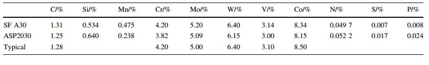
ASP2030 (A30) steel is a W-Mo-Cr-V-Co alloyed powder metallurgical steel containing 1.28% C,4.2% Cr,5.0% Mo,6.4% W,8.5% Co and 3.1% V (mass fraction). The addition of cobalt with about 8.5% (mass fraction) can improve modulus of elasticity,compressive strength,temper resistance,and high temperature properties[1]. The primary and secondary precipitated carbides consisting of W,Mo,Cr and V are favorable to high wear resistance,secondary hardening,and stable hardness up to temperature as high as 500 ℃[2].
The traditional and most frequently used method to produce tool steels is conventional ingot casting or alternatively continuous casting of the melt followed by forging or rolling processes. If the higher demands on properties such as ductility,homogeneity or cleanliness have to be fulfilled,the remelted tool steels are usually applied. The used metallurgical technologies are the electro-slag remelting (ESR) or the vacuum-arc-remelting (VAR) process[3, 4].
Due to the rapid solidification of the powder particles,powder metallurgy (PM) allows to intensively widen up the limits of steel compositions. Therefore the development of PM tool steels concentrates on the high alloyed steel compositions with very high carbide contents. A30 steel produced by PM exhibits a homogeneous microstructure and outstanding mechanical properties with uniform distribution of carbide phases[5].
Spray forming has now been developed to a new and important technology for the production of tool steels[2, 6]. It is based on the atomization of a melt,which allows using the benefits of a rapid solidification. The main difference between spray forming and PM is that spray forming directly produces a solid billet whereas in PM the powders have to pass a complex and expensive process of classification,mixing and compaction in order to achieve a solid block of steel. As a new technique,spray forming is able to provide materials with well-balanced compositions to meet customer’s demands with improved properties[6, 7, 8, 9].
As mentioned above,spray forming technology can be used within a large extension. For example,Zhang et al.[10, 11] produced Cr12MoV steel by spray forming as a new type of roll,which was characterized by a relatively homogeneous and fine microstructure with fine carbides dispersion and less segregation of Cr. Ikawa et al.[12] also produced mill rolls by spray forming. The service life of the spray formed (SF) rolls was two times higher than that of rolls produced by the conventional cast with refined microstructures. Furthermore,Lee et al.[13] and Zhang et al.[14] successfully produced high speed steel (HSS) by spray forming with better microstructural homogeneity and good mechanical properties. In addition,Yan et al.[15] obtained a fine microstructure of V4 steel through spray forming followed by rolling and annealing.
In this paper,microstructure,carbides,heat treatments and properties of SF A30 steels were investigated in order to achieve further insights to the possibility of using spray forming to produce A30 steel.
2 Experimental proceduresThe compositions of SF A30 and ASP2030 steels are listed in Table 1. The steel was melted in a vacuum induction furnace. The molten steel was poured into the tundish and transferred into a close coupled atomizer via the tundish’s bottom nozzle. The molten metal flow rate was approximately 0.5 kg/s and nitrogen with a pressure of 1.5 MPa was used as atomizing gas. The atomized droplets were cooled and accelerated to a substrate with a rotation speed of 90 r/min to form a round billet. A properly adjusted downward movement of the growing billet allowed for a permanently constant distance between the atomizer and the billet during spray forming. The whole spray forming process was completed within about 180 s to form a billet with a diameter of about 200 mm and height of 230 mm. The billet was put into a furnace at 900 ℃ for 3 h immediately after spray. The schematic diagram of the spray forming process and the obtained billet are shown in Figs. 1a,b[16].
 |
| Fig. 1 Schematic diagram of the spray forming process |
After heating at 1 150 ℃ for 3 h,the billet was forged between 950 ℃ and 1 150 ℃ with the forging ratio 5-9 and then cooled to room temperature in the sand. As-forged specimens were annealed at different temperatures (850 ℃,880 ℃,910 ℃) for 4 h. Then the specimens were cooled to 700 ℃ at a rate of 10 ℃/h,and finally cooled in air. The optimal specimens,which were obtained by forging at 1 150 ℃ and then annealing at 910 ℃ with better spheroidal carbides and lower hardness than others,were chosen from the annealed specimens and compared with ASP2030 steel (UDDEHOLM,Sweden).
The forged and annealed A30 steel was treated as following in order to perform mechanical tests: austenitized at 1 050,1 100,1 120,1 140,1 160,1 180 ℃,respectively for 10 min in a resistance-heated furnace,oil quenched,and triple-tempered in the range of 530-580 ℃ for 1 h. The hardness measurements were performed by Rockwell C (HRC) and average values from six readings were reported. Impact toughness tests were performed on the materials at various stages using samples with dimensions of 7 mm 9 10 mm 9 55 mm at room temperature. Threepoint bending tests were used to determine the bend fracture strength with dimensions of Ø 5.3 mm 9 116 mm and the span of 90 mm at a bending rate of 5 mm/min.
The specimens were ground,polished and etched in nitric alcohol etchant (alcohol: 96 mL,HNO3: 4 mL) and then analyzed by the optical microscopy (OM),scanning electron microscopy (SEM),electron probe microanalysis (EPMA). Thin foils for the transmission electron microscopy (TEM) investigations were prepared by the twin-jet polishing at -20 ℃,using 5% perchloric acid and 95% ethanol as electrolyte. The X-ray diffraction (XRD) was used to analyze the phase components of the SF A30 steel.
3 Results and discussion 3.1 Microstructure of SF A30 steelThe typical structure of the A30 steel produced by spray forming is shown in Fig. 2. It reveals a fine and homogeneous structure with an extremely fine ledeburitic carbide network with a mesh size approximately from 10 lm to 20 lm. The SF A30 steel has a higher cooling rate,which makes the carbides refined notably.
 |
| Fig. 2 SEM micrograph of SF A30 steel |
Figures 3 and 4 show the SEM images of SF A30 and the corresponding element distribution maps,such as Cr,C,W,Mo,V and Co. The results indicate that the segregation of alloy elements is weakened. Carbides which are rich with tungsten and molybdenum appear as bar or strip,forming near-mesh in the matrix,which is harmful to the toughness of the material. Vanadium-rich carbides uniformly distribute on the grain boundaries,and coarse vanadium depleted carbides could be found in the matrix. Spray forming effectively reduces the segregation of the elements in SF A30 HSS,and more evenly distributed carbides are obtained.
 |
| Fig. 3 Secondary electron image of SF A30 steel |
 |
| Fig. 4 Element distribution maps in SF A30 steel |
The XRD reveals the presence of martensite and retained austenite in the matrix (see Fig. 5). The cause of the retained austenite,as reported for SF D2 and rapid solidification D2 steel[9],is that a lot of alloying elements are dissolved in the austenite during the spray forming and the rapid solidification stabilizes the austenite and therefore decreases the martensite start temperature Ms. In addition,the representative morphology of the martensite is shown in Fig. 6.
 |
| Fig. 5 XRD spectrum of the SF A30 steel |
 |
| Fig. 6 Twin martensite morphology in SF A30 steel |
It is important for carbides to provide high hardness and high wear resistance of the steels. The alloy compositions and the solidification process are two main factors which affect the solidification structure of HSS. The XRD spectrum of carbides obtained from electrolysis and extraction is shown in Fig. 7. The carbide types in the SF A30 HSS are identified as MC,M2C and M6C. Identification of the three types of carbide in the matrix is shown in Fig. 8 by TEM.
 |
| Fig. 7 XRD spectrum of SF A30 steel |
 |
| Fig. 8 TEM micrographs of the M2C, M6C and MC carbides in the as-sprayed A30 steel and their selected area diffraction patterns, respectively, as shown by arrows |
The solidification process during spray forming can be divided into two stages: gas atomization (rapid cooling) and droplet consolidation (relatively slow cooling)[17]. The vanadium is a strong carbide-forming element and the eutectic reaction L → γ + MC will happen firstly during the solidification process[18, 19, 20]. It is known that M2C carbide can be formed as a metastable phase during rapid cooling or at high carbon contents. Carbide in the overspray high speed steel particles was identified as MC and M2C through XRD by Lee et al.[21]. During the spray forming process,the atomized globular droplets with different diameters solidify at different rates. As small particles may be solidified during flight,medium sized particles may be partly solidified and larger particles are still completely liquid. The particles hitting the surface of the target have a high velocity and a high energy. They build a mushy zone,which consists of both liquid and solidified metal and has a thickness of only a few millimeters on the top of target. This mushy zone exists during the whole spray forming process. Due to their high kinetic energy,smaller dendritical or semi solidified particles get smashed during their impact on the target and melt up again[22]. The remaining liquid enriched with segregating alloying elements forms a liquid network and further solidification continues with the formation of eutectic M6C,M2C and MC carbides,which results in the creation of carbide cell structures. At the same time,M2C carbides formed from the droplets during atomizing process will transform into the stable M6C carbides due to the high temperature of the billet[21]. The MC carbide is known to be formed over a wide temperature range and is observed inside the cell as well as at cell boundary in the SF A30 steel.
3.3 Carbide refining process of SF A30 steelFigure 9 shows the distribution of carbides after annealing at 1 150 ℃ for 3 h. Figure 10 shows the transformation of M2C carbides into M6C and MC carbides after heating at 1 150 ℃ for 3 h. The shapes and distributions of the carbides change obviously.
 |
| Fig. 9 Optical micrograph of SF A30 steel after solution treatment at 1 150 ℃ for 3 h |
 |
| Fig. 10 XRD spectrum of the as-sprayed A30 steel after solid solution treatment |
Solid solution treatment is a process to dissolve eutectic carbides. It is a hot activation procedure of different alloying atoms. Their diffusion capability is determined by temperature. For reheated metastable eutectic M2C-type carbides,the following reaction occurs: M2C+ Fe(γ) → M6C + MC[3, 4, 13]. This reaction,that is the peritectoid type,takes considerable time to complete,except at high temperature,when rapid diffusion of the alloying elements can occur. The eutectic colonies become separated and break up,and M6C and MC carbides generate during the preceding decomposition. In order to decrease the total surface free energy,carbides become spherical in shape.
However,high temperature decomposition and solid solution treatment could not completely change the morphology and distribution of the carbides. Special attention is paid to establish the deformation conditions that lead to the breakdown of the primary grains and ledeburitic carbides[7, 23]. The forging process would be undertaken in progressive smaller strain steps. The total strain would allow not only break-down of the carbide structure but also dynamic recrystallization to refine the matrix structure and relax the residual strain between deformations. Therefore,forging is necessary to refine the size and distribution of the carbides[3, 24].
The microstructure of SF A30 steel is shown in Fig. 11a after forging and annealing,and no obvious cracks are found. The carbide networks were broken up and fine carbides were obtained during the forging process between 950 ℃ and 1 150 ℃,which was attributed to the synergetic effects from both spray forming and forging for microstructure refinement. The average size of carbide is in a range of 1-6 lm,which is close to the equivalent in the PM ASP2030 steel (see Fig. 11b). The enhanced workability of SF A30 steel is also attributed to the refined microstructure with small equiaxed grains and evenly distributed fine spheroidal carbides.
 |
| Fig. 11 Comparison of the annealed optical micrographs a SF A30, b ASP2030 |
Figure 12a shows the SEM microstructure of SF A30. It is similar to ASP2030,which is shown in Fig. 12b. The carbides are evenly distributed within the matrix and are close to a regular spherical shape with a diameter of less than 6 lm. The sizes of carbides are slightly larger than those in ASP2030 steel.
 |
| Fig. 12 SEM micrographs of SF A30 a and ASP2030 b austenitized at 1 150 ℃ and triple-tempered at 560 ℃ |
Heat treating of SF A30 steel is shown in Fig. 13a,where hardness after tempering is plotted versus austenitizing temperature. Hardness increases with increasing austenitizing temperature. For a given austenitizing temperature,the increase in the tempering temperature will result in a small decrease in hardness. Almost all impact energies at different austenitizing temperatures reach peaks at the tempering temperature of 560 ℃,as shown in Fig. 13b. Figure 13 indicates the hardness variation with changing austenitizing and tempering temperatures,and for high hardness the higher austenitizing temperature can give a higher supersaturation and benefit the efficient precipitation of finer secondary carbides during tempering. The decline of hardness with increasing tempering temperature will be induced by the overaging at higher temperature for the growth or coarsening of the secondary carbides.
 |
| Fig. 13 Responses in hardness and impact energy with heat treatments of SF A30 steel |
Austenite will transfer to martensite during tempering. A smaller amount of austenite transforms to martensite during cooling for the second tempering cycle. Long tempering time is required for carbide precipitation,because of the low diffusion rates of the alloying elements (excluding carbon). If the tempering temperature is not sufficiently high,this will result in some of the alloy elements remaining in solution. Hence,an increase of hardness can be observed due to solid-solution strengthening. However,the increase in hardness with austenitizing temperature can also be attributed to the presence of increasing amounts of fine secondary carbides precipitated during tempering. Considering the effect of tempering temperature,it is clear that the impact toughness is a mechanical property that depends upon both the austenitizing and tempering temperature. The correlation between the hardness and the impact toughness is fairly well at austenitizing temperature from 1 140 ℃ to 1 160 ℃ and at a higher tempering temperature from 550 ℃ to 570 ℃. The combined results in Fig. 13 can be applied for the selected heattreatment parameters aimed at an optimal ratio between the toughness and hardness for this SF HSS[2].
Figure 14 presents the hardness and bend test results of SF A30 and ASP2030 HSS at different austenitizing temperatures and triple-tempered at 560 ℃ for 1 h. For both materials,the hardness of SF A30 steel is slightly higher than that of ASP2030 steel at the same heat treating condition. The longitudinal bend strength is estimated to be about 5 500 MPa,which isalmostclose tothatofASP2030eventhat the hardness of SF A30 is slightly higher than ASP2030 steel.
 |
| Fig. 14 Hardness and bend properties of SF A30 and ASP2030 steels at different austenitizing temperatures |
The results shown in Fig. 14 are directly related to microstructure,carbide distribution and hardness. The higher alloy content in the SF A30 steel leads to a higher hardness than ASP2030,which will decrease the bend strength. Based on previous reports[2, 8, 13, 25],carbide size and distribution significantly affected the longitudinal toughness. The decomposition and solid solution treatment prior to hot forging facilitated the even dispersion of fine carbides during the hot-working process,which increased the bend strength[21]. The carbide size and distribution in SF A30 explained the similar longitudinal values and the production of SF A30 steel with excellent toughness could be expected.
4 ConclusionsThe SF A30 steel exhibits fine equiaxed grains with homogeneously distributed carbides. The rapid solidification inherent during spray forming process prevented segregation and formation of irregular carbides,and enhanced he hot-working ability. Excellent microstructure and toughness were obtained by the decomposition and breakup of the carbides during hot working and annealing process. Processing conditions,regarding heating treatment,are important variables for industrial production of SF A30 steel. The microstructure properties of A30 steel produced by spray forming indicate that this process can be considered a cost-effective route for production of high speed steels,and other highly alloyed steels.
Acknowledgments This research was financially supported by Baosteel Research Institute,People’s Republic of China.| 1. | Moon HK, Lee KB, Kwon H (2008) Influences of Co addition and austenitizing temperature on secondary hardening and impact fracture behavior in P/M high speed steels of W-Mo-Cr-V(-Co) system. Mater Sci Eng A 474:328-334 |
| 2. | Mesquita RA, Barbosa CA (2004) Spray forming high speed steel-properties and processing. Mater Sci Eng A 383:87-95 |
| 3. | Zhou B, Shen Y, Chen J, Cui ZS (2011) Breakdown behavior of eutectic carbides in high speed steel during hot compression. J Iron Steel Res Int 18:41-48 |
| 4. | Hetzner DW (2001) Refining carbide size distributions in M1 high speed steel by processing and alloying. Mater Charact 46:175-182 |
| 5. | Wronski AS, Wright CS, Bolton JD, Bienvenu Y, Jeandin M, Smith AB (1991) PM HSS for aerospace automotive and cutting tool applications. Met Powder Rep 46(50-51):53-55 |
| 6. | Grant PS (1995) Spray forming. Prog Mater Sci 39:497-545 |
| 7. | Rodenburg C, Krzyzanowski M, Beynon JH, Rainforth WM (2004) Hot workability of spray-formed AISI M3:2 high-speed steel. Mater Sci Eng A 386:420-427 |
| 8. | Schulz A, Uhlenwinkel V, Escher C, Kohlmann R, Kulmburg A, Montero MC, Rabitsch R, Schützenhöfer W, Stocchi D, Viale D (2008) Opportunities and challenges of spray forming high-alloyed steels. Mater Sci Eng A 477:69-79 |
| 9. | Bhargava AK, Tiwari AN (1992) Effect of rapid solidification and heat treatment on D2 steel. Int J Rapid Solidif 7:51-66 |
| 10. | Zhang JG (2003) Research in spray forming technology and its applications in metallurgy. J Mater Process Technol 138:357-360 |
| 11. | Zhang JG, Xu HB, Shi HS, Wu JS, Sun DS (2003) Microstructure and properties of spray formed Cr12MoV steel for rolls. J Mater Process Technol 111:79-84 |
| 12. | Ikawa Y, Itami T, Kumagai K, Kawashima Y, Leatham AG, Coombs JS (1990) Spray deposition method and its application to the production of mill rolls. ISIJ Int 30:756-763 |
| 13. | Lee ES, Park WJ, Baik KH, Ahn S (1998) Different carbide types and their effect on bend properties of a spray-formed high speed steel. Scr Mater 39:1133-1138 |
| 14. | Zhang Y, Zhang GQ, Li Z, Li ZD, Yuan H, Xu WY, Liu N, Tian SF (2007) Analysis of twin-nozzle-scanning spray forming process and spray formed high speed steel (HSS). J Iron Steel Res Int 14:7-10 |
| 15. | Yan F, Xu Z, Shi HS, Fan JF (2008) Microstructure of the spray formed Vanadis 4 steel and its ultrafine structure. Mater Charact 59:592-597 |
| 16. | Cui CS, Fritsching U, Schulz A, Tinscher R, Bauckhage K, Mayr P (2005) Spray forming of homogeneous 100Cr6 bearing steel billets. J Mater Process Technol 168:496-504 |
| 17. | Yu FX, Cui JZ, Ranganathan S, Dwarakadasa ES (2001) Fundamental differences between spray forming and other semisolid processes. Mater Sci Eng A 304-306:621-626 |
| 18. | Wei SZ, Zhu JH, Xu LJ (2005) Research on wear resistance of high speed steel with high vanadium content. Mater Sci Eng A 404:138-145 |
| 19. | Zhou H, Wang JG, Jia SS, Keisaku OGI (1997) Solidified microstructures and phases of high speed steels containing different V and C content. Acta Metall Sin 33:838-843 |
| 20. | Luan YK, Song NN, Bai YL, Kang XH, Li DZ (2010) Effect of solidification rate on the morphology and distribution of eutectic carbides in centrifugal casting high-speed steel rolls. J Mater Process Technol 210:536-541 |
| 21. | Lee ES, Park WJ, Jung JY (1998) Solidification microstructure and M2C carbide decomposition in a spray-formed high-speed steel. Metall Mater Trans 29A:1395-1404 |
| 22. | Xu Q, Lavernia EJ (1999) Microstructure evolution during the initial stages of spray atomization and deposition. Scr Mater 41:535-540 |
| 23. | Pan FS, Wang WQ, Tang AT (2011) Phase transformation refinement of coarse primary carbides in M2 high speed steel. Prog Nat Sci 21:180-186 |
| 24. | Večko Pirtovšek T, Kugler G, Godec M, Terčelj M (2011) Microstructural characterization during the hot deformation of 1.17C-11.3Cr-1.48V-2.24W-1.35Mo ledeburitic tool steel. Mater Charact 62:189-197 |
| 25. | Meurling F, Melander A, Tidesten M, Westin L (2001) Influence of carbide and inclusion contents on the fatigue properties of high speed steels and tool steels. Int J Fatigue 23:215-224 |