The article information
- Y. Karpat, O. Bahtiyar
- Tool geometry based prediction of critical thrust force while drilling carbon fiber reinforced polymers
- Advances in Manufacturing, 2015, 3(4): 300-308
- http://dx.doi.org/10.1007/s40436-015-0129-y
-
Article history
- Received: 28 August 2015
- Accepted: 6 November 2015
- Published online: 8 December 2015
2 Turkish Aerospace Industries Inc., Ankara 06980, Turkey
Due to the desirable material properties such as high strength to weight ratio,high resistance to corrosion,and low thermal expansion,usage of carbon fiber reinforced polymers (CFRPs) has been especially increasing. Drilling is a commonly used operation in the aerospace manufacturing industry and the quality of the drilled holes is important. Drilling process parameters,drill geometry,and drill tool material must be carefully selected in order to obtain holes with acceptable quality. An important problem related to the hole quality in drilling CFRPs is delamination which is the separation of CFRP plies during drilling as a result of forces acting on the laminate. Therefore,it is important to select drilling process parameters considering process economics and part quality specifications.
Drilling of CFRPs has been studied extensively in the literature. A considerable amount of work has been conducted on calculating ‘‘critical thrust force’’ which is a limit value of thrust force beyond which delamination initiates [1]. Analytical models have been developed to predict the critical thrust force based on mechanical properties of the CFRPs [2, 3]. It must be noted that due to the abrasive nature of carbon fibers,tool wear develops rapidly and changes the conditions of drilling. Tool wear during drilling has also been studied in detail in the literature. Rounding of the cutting edges as they wear out has been observed in Refs. [4, 5]. Increasing force due to tool wear also leads to hole quality problems.
The relationship between process parameters,drill geometry and process outputs has also been studied [6, 7, 8]. It was shown that feed rate must be kept low in order to keep thrust forces low during drilling to minimize the likelihood of delamination. A straightforward option to retard tool wear is to utilize polycrystalline diamond (PCD) as tool material. PCD drills are known to perform better compared to uncoated carbide tools due to their superior material characteristics such as lower coefficient of friction and higher toughness. In a recent study,Karpat et al. [9] compared performances of different PCD drills while drilling CFRPs and investigated the trade-offs in drill geometries through experimental analysis of drilling forces and torques.
Modeling of CFRP drilling process is crucial to understand the influence of drill geometry on drilling process outputs and consequently to develop better drill designs or to select drilling parameters. Due to the complexity of the drilling process,mechanistic modeling approaches have been used to model drilling forces and torques. Lazar and Xirouchakis [10] made an extensive review of existing mechanistic drilling models in the literature and also introduced a new mechanistic model to predict drilling forces. Karpat et al. [11] proposed a mechanistic drilling model for double point angle PCD drills where cutting force coefficients were represented as a function of fiber direction. The same model is used in this study to investigate the influence of different PCD drill geometries on drilling forces and torques. Meng et al. [12] proposed a new model by considering the force fluctuations due to varying fiber directions during the drilling process. Sadek et al. [13] used a mechanistic thrust force and torque model to predict delamination while drilling CFRPs. Their model also includes a thermal model of drilling CFRPs which is an important consideration in terms of interior hole quality. Analytical and finite element modeling techniques have also been employed in CFRP drilling process. Hocheng and Tsao [14] developed an analytical model based on material properties of CFRP laminates which was able to predict critical thrust force based on drill geometries. They recommended the use of special drill designs where the thrust force was directed towards the drill periphery instead of being concentrated at the center. In a recent study,Isbilir and Ghassemieh [15] used finite element modeling of drilling including real drill geometry to study delamination. The advantages of step drills over twist drills were shown based on finite element simulations.
In a recent study,Karpat and Bahtiyar [16] calculated the total drilling power for different drill designs and showed that most of the drilling power was due to torque and the drill design which yielded lower torque performs better in terms of tool wear and hence delamination. Selecting a large feed resulted in a shorter tool path inside hole which decreased tool wear. It was also shown that increasing feed up to a certain level allowed for decreasing total drilling power. In this paper,the same set of drills in Ref. [16],which were prepared by the same tool manufacturer from the same PCD material,are considered again. The goal is to select feed rate based on tool geometry which will not yield delamination and prolong tool life at the same time. The paper is organized as follows. Firstly, the experimental setup and PCD drill geometries are introduced. Secondly,the experimental drilling forces and torques are presented. Thirdly,the cutting force and edge coefficients are calculated and the drilling model is validated. Lastly,the trade offs in drill designs are explained based on the findings and a procedure for feed rate selection is explained.
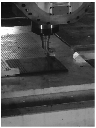
2 Experimental setupExperiments were performed at a CNC machining center under wet conditions by using an emulsion type coolant. An aluminum back-up plate with 8 mm diameter holes was used to support the CFRP laminate. A Kistler 9123 rotating dynamometer was used to measure the drilling forces and torques. Drilling tests used intermediate modulus UDCFRP laminates of 9 mm thickness,with equal fiber directions repeating in a sequence of 0°/45°/90°/135° with two layers of 45° and 135° laminates on the top and bottom surfaces. The intermediate modulus carbon fiber reinforced epoxy resin unidirectional tape used in this study has 59% fiber volume with 2 690 MPa tensile strength. Figure 1 shows the experimental setup.
 |
| Fig. 1 Experimental CFRP drilling setup |
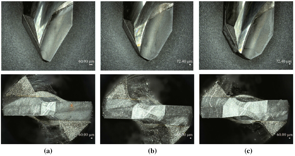
Four different PCD drills with different edge lengths were custom fabricated by the tool manufacturer as shown in Fig. 2. Three of them (code as D1,D2 and D3) were used to develop a mechanistic model and the last one (D4) was used for model validation. PCD drills are fabricated to have the same chisel edge length. The diameter of the drills are 6.4 mm and the edge radius of all the drills are measured to be around 10 lm as measured with a laser scanning microscope (Keyence VKX 110).
 |
| Fig. 2 Double point angle drill geometries a D1, b D2, c D3 |
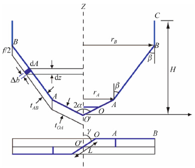
A generalized design for double point angle PCD drills was developed in Ref. [11]. It is briefly illustrated in Fig. 3. In Fig. 3,O'-O represents the chisel edge region; OA shows the primary drilling region; AB shows the secondary drilling region; and BC shows the tertiary drilling region. LOA, LAB,LBC represent the lengths of OA,AB,BC,respectively. The length and angle of the chisel edge are represented with L and γ,respectively. The uncut chip thicknesses for primary and secondary drilling regions are shown with tOA and tAB,respectively. The drill has zero helix angle.
 |
| Fig. 3 Generalized double tip point angle PCD drill geometry [11] |
Table 1 summarizes the actual tool geometry measurements performed by using Keyence VHX 1000 digital microscope.
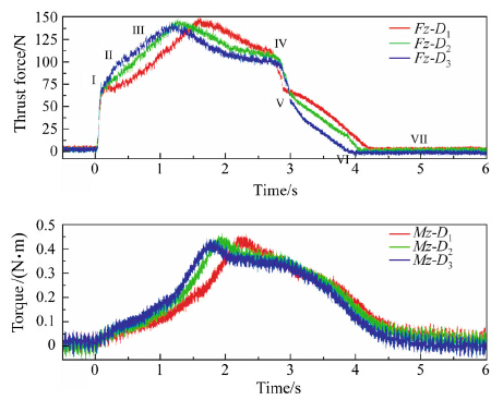
Figure 4 shows thrust force and torque measurements for drills D1,D2,and D3. Based on these measurements,the drills yield similar peak thrust forces and torques,although they have quite different primary drilling edge lengths. A drilling cycle with the double point angle PCD drill can be identified with seven distinct phases (I-VII) of drilling (see Fig. 4). The entry of the chisel edge corresponds to point (I). Since each drill employs the same chisel edge,the same level of forces is recorded as expected. The entry of the primary drilling edge (OA) corresponds to point (II). It must be noted that the increase in torque at this point is quite small.
 |
| Fig. 4 Thrust force and torque measurements with drills D1, D2, and D3 as a function of feed at 40 lm/r and 5 000 r/min |
Between points (II) and (III),the secondary drilling region (AB) enters the hole. The rate of increase in thrust force in this region is lower compared to (I)-(II) since the chip thickness is lower in that region. Peak thrust force is reached at the end of the secondary drilling zone (III). The torque reaches its peak value when the tertiary drilling region fully enters the hole between (III) and (IV). Rubbing action between the drill and the material is responsible for the increase in torque. As the length of the tertiary drilling zone increases,the peak value of torque also increases. The thrust force decreases from (III) to (IV) is believed to be due to thermal softening of the material as drilling progresses. Thrust force decreases rapidly with a similar rate observed at the hole entry as soon as the chisel edge,primary drilling edge (IV)-(V),secondary drilling edge (V)- (VI),and tertiary drilling edge (VI)-(VII) leave the cut. The torque stays almost the same between (IV) and (V) since the secondary and tertiary cutting edges are still in contact with the material. The torque decreases continuously between (V)-(VII) until the drill completely leaves the cut. According to the mechanistic drilling model proposed by Karpat et al. [11],total drilling thrust force (Fz) and torque (T) can be written as

Forces and torques corresponding to each drilling region can be represented using a mechanistic model as


In a mechanistic force modeling approach,drilling thrust forces and torques are related to the uncut chip area through calculation of cutting coefficients (Kzp,Kzs,Kcp, Kcs) and edge force coefficients (Kzep,Kzes,Kcep,Kces,Kp), which represent the influence of drills’ cutting edge and material properties on the forces and torques. In Eqs. (3)- (7),the subscript ‘‘p’’ represents primary and subscript ‘‘s’’ represents secondary drilling regions. These unknown cutting and edge force coefficients can be calculated through drilling experiments performed at various feeds. Figures 5-7 show the measurements of thrust force and torque obtained for each drill at different feeds.
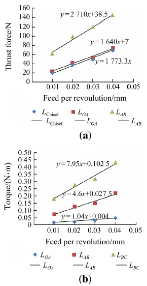 |
| Fig. 5 Thrust force and torque measurements with drill D1 |
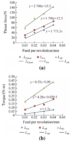 |
| Fig. 6 Thrust force and torque measurements with drill D2 |
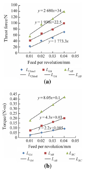 |
| Fig. 7 Thrust force and torque measurements with drill D3 |
Each point on the linear curve represents measurements at a characteristic point as indicated. A linear fit for each region is also shown. By using the linear fit equations,the unknown variables in Eqs. (3)-(7) can be solved in reverse fashion. The chisel edge forces can be represented as a function feed,again using a linear fit. Table 2 shows the identified cutting and edge force coefficients for each drill. It must be noted that the height of each PCD cutting edge (H in Fig. 3) is the same. Therefore,as primary cutting edge length increases,the length of the tertiary edge decreases. The result is reflected on the calculation of the coefficient Kp in Table 2.
Figure 8 shows the identified force coefficients for primary and secondary edges as a function of edge lengths. From Fig. 9a,it can be seen that the design intent of drill D1 is to bear the thrust forces at the primary drilling edge and keep the thrust force intensity low on the secondary drilling edge to protect it from rapid tool wear. Considering that the secondary and tertiary drilling edges will leave the hole last,the idea is to keep the force and torque intensity as low as possible to keep these edges as sharp as possible. As for drill D2,the purpose is to balance the load intensity between primary and secondary edges. For the primary edge length of 0.8 mm,the thrust load sharing between primary and secondary edges are equal. For drill D3,the design intent is to lower the thrust forces at the hole exit by decreasing the thrust forces at the primary drilling region. Due to a shorter secondary drilling edge,the torque intensity in this region is higher. Karpat and Bahtiyar [16] showed that drilling torque may be related to edge rounding of the drill,the design intents of drill D1 and D3 contradict one another. It must be noted that the thickness of the laminate may also be an important parameter. For thin laminates,using a drill design with long secondary drilling edge may not be appropriate,since the tip of drill may leave the hole while the drilling forces are increasing (I-III). In such a case,a drill design with short secondary edge must be selected.
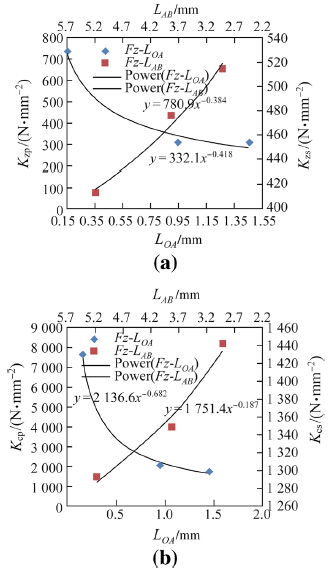 |
| Fig. 8 Identified force coefficients as a function of primary drilling edge length |
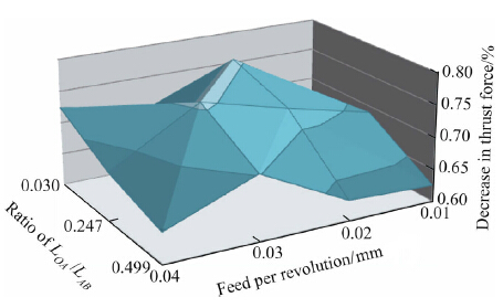 |
| Fig. 9 The relationship between thrust force drop versus edge length ratio and feed |
Based on the calculations shown in Fig. 8,it is possible to define the force coefficients as a function of primary edge length as

It is also observed from thrust force measurements that the decrease in thrust forces between (III) and (IV) changes as a function of drill geometry and feed. Figure 9 shows the twodimensional plot of decreasing percentage in thrust force (Fz_IV/Fz_III) as a function of feed and primary to secondary edge length ratio (LOA/LAB). A complex relationship exists between the force drop and drill geometry. The highest force drop is observed with a long primary drilling edge length drill. This relationship is believed to be related to development of temperatures during drilling operation. The strength of the CFRP material depends on the temperatures and the distribution of temperatures depends on the drill geometry.A detailed analysis of drilling temperatures is needed for better understanding. As the laminate thickness increases,the influence of temperatures becomes more important and it directly affects the tool wear.
5 Validation of the mechanistic drilling modelThe general representations of primary and secondary drilling edge cutting force coefficients shown in Eqs. (3)- (11) can be used to predict thrust force and torque at a given feed for a given geometry (i.e.,LOA). In order to validate the drilling model,a fourth drill (D4) is used. The geometry of drill D4 is shown in Fig. 10. The primary edge length is 0.5 mm and the tip angles of the primary and secondary drilling edges are 60° and 30°,respectively.
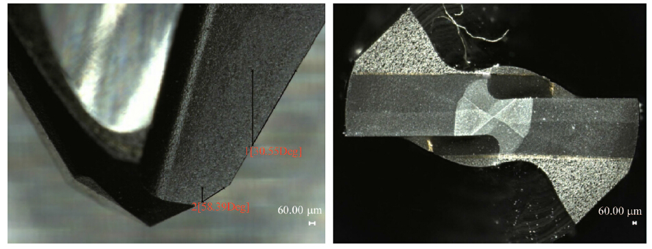 |
| Fig. 10 Drill geometry used for validation study |
Figure 11a shows the thrust force and torque measurements obtained from drill D4. Figure 11b shows the predicted thrust force and torque using the mechanistic drilling model. A simple computer code has been developed to simulate drilling forces and torques. In order to model thrust force decrease between points (III) and (IV),a constant value of 0.7 is used based on experimental observations made in the previous section. A good match between measurements and predictions is obtained.
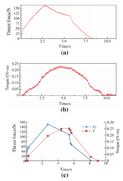 |
| Fig. 11 Drilling thrust force and torque a measurements and b predictions at 100 mm/min feed rate at 5 000 r/min |
Figure 12 shows the measured and calculated thrust forces at points (III) and (IV) as a function of feed for drill D4. The predictions at points (III) and (IV) are important since they are directly related to delamination. The measurements and predictions are also in good agreement. As feed increases,the forces at the hole exit also increase. In order to observe the influence of drilling conditions on the delamination,some additional tests were also conducted to investigate the delamination on the hole exit.
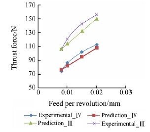 |
| Fig. 12 Thrust force measurements and predictions for drill D4 |
Figure 13 shows the hole exits obtained after drilling with drill D4. The feed values range between 0.01 mm/r and 0.06 mm/r. The rotational speed was set at 5 000 r/min. As expected,the results reveal that as feed increases,hole exit quality deteriorates. The delamination started at feed value of 0.02 mm/r for D4 (see Fig. 13b). Based on this information,the critical thrust force can be identified to be around 70-80 N (see Fig. 12).
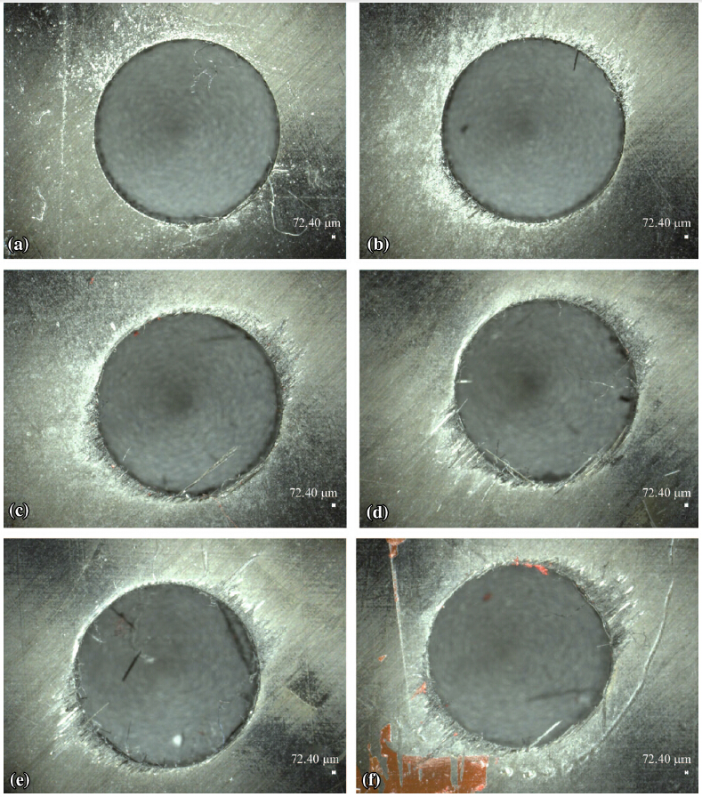 |
| Fig. 13 Hole exits at feed values of a 0.01 mm/r, b 0.02 mm/r, c 0.03 mm/r, d 0.04 mm/r, e 0.05 mm/r, f 0.06 mm/r for D4 |
The mechanistic model can be used to perform simulations by considering two different critical thrust force values such as 70Nand 80 N. The maximum allowable feed rate as a function of primary drilling edge is calculated using the drilling simulation model (see Fig. 14). For 0.5 mm primary drilling edge length and 70 N critical thrust force value,the maximum feed rate is 30 mm/min,which is reasonable considering the results shown in Fig. 13.
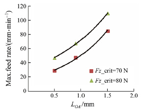 |
| Fig. 14 Maximum allowable feed rate as a function of primary drilling edge obtained from the drilling model |
Figure 15 shows the hole exits as a function of increasing feed per revolution for D2 where the primary edge length is 0.945 mm. It can be seen that the holes with acceptable exit quality are obtained at 40 mm/min, 50 mm/min,and 75 mm/min feed rates which are in good agreement with the calculations (see Fig. 14).
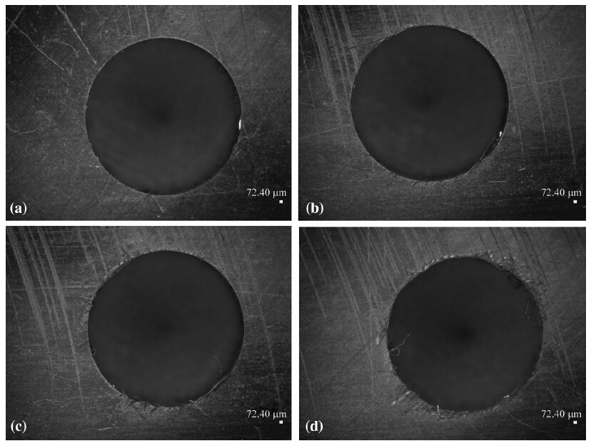 |
| Fig. 15 Hole exits obtained with D2 at feed rates of a 0.008 mm/r, b 0.01 mm/r, c 0.015 mm/r, and d 0.02 mm/r |
In this study,a mechanistic drilling thrust force and torque prediction model has been used to obtain a generalized model of drilling with double point angle PCD drills. It has been shown that suitable feed rate values for a given drill design can be successfully selected based on the generalized model for double angle drill designs and experimentally measured critical thrust force value. The results are validated through delamination studies.
The approach is also used to explain the trade-offs in drill geometry designs. Our investigations reveal that longer primary drilling edge length allows drilling with larger feed rates. This is in accordance with a previous finding in the literature which suggests that thrust forces must be directed towards drill periphery rather than being concentrated at the center. However,using shorter primary drilling edge helps decrease torque intensity at the outer edge of the drill which may translate into better tool wear performance in the long term but the allowable feed rate must be selected lower. Maintaining the balance between productivity and longevity through selection of drill geometry and drilling parameters is shown to be possible in this study. The methodology shown here can be used to design tailored drills for a given CFRP laminate.
It must be noted that the influence of spindle speed,which is known to effect the total drilling power hence the temperature distributions inside the hole,is not considered in this study. Based on the measurements,it is observed that the change in thrust force and torque during drilling varies as a function of drill geometry which is believed to be related to temperature distributions during drilling. Integration of thermal modeling of drilling into mechanistic thrust force and torque prediction models is left as a future work.
Acknowledgement The authors would like to thank The Scientific and Technological Research Council of Turkey TU¨ BI˙TAK-TEYDEB for the financial support for the project.
| 1. | König W, Wulf C, Graß P et al (1985) Machining of fibre reinforced plastics. CIRP Ann Manuf Technol 34(2):537-548 |
| 2. | Ho-cheng H, Dharan CKH (1990) Delamination during drilling in composite laminates. J Manuf Sci Eng 112(3):236-239 |
| 3. | Zhang LB, Wang LJ, Liu XY (2001) A mechanical model for predicting critical thrust forces in drilling composite laminates. Proc Inst Mech Eng Part B 215(2):135-146 |
| 4. | Faraz A, Biermann D, Weinert K (2009) Cutting edge rounding: an innovative drill wear criterion in drilling CFRP composite laminates. Int J Mach Tools Manuf 49(15):1185-1196 |
| 5. | Karpat Y, Değer B, Bahtiyar O (2012) Drilling thick fabric woven CFRP laminates with double point angle drills. J Mater Process Technol 212(10):2117-2127 |
| 6. | Shyha IS, Aspinwall DK, Soo SL et al (2009) Drill geometry and operating effects when cutting small diameter holes in CFRP. Int J Mach Tools Manuf 49(12):1008-1014 |
| 7. | Abraõ AM, Rubio JCC, Faria PE et al (2008) The effect of cutting tool geometry on thrust force and delamination when drilling glass fibre reinforced plastic composite. Mater Des 29(2):508-513 |
| 8. | Duraõ LMP, Gonçalves DJS, Tavares JMRS et al (2010) Drilling tool geometry evaluation for reinforced composite laminates. Compos Struct 92(7):1545-1550 |
| 9. | Karpat Y, Değer B, Bahtiyar O (2014) Experimental evaluation of polycrystalline diamond tool geometries while drilling carbon fiber-reinforced plastics. Int J Adv Manuf Technol 71(5-8):1295-1307 |
| 10. | Lazar MB, Xirouchakis P (2013) Mechanical load distribution along the main cutting edges in drilling. J Mater Process Technol 213(2):245-260 |
| 11. | Karpat Y, Bahtiyar O, Değer B et al (2014) A mechanistic approach to investigate drilling of UD-CFRP laminates with PCD drills. CIRP Annals-Manuf Technol 63(1):81-84 |
| 12. | Meng Q, Zhang K, Cheng H et al (2015) An analytical method for predicting the fluctuation of thrust force during drilling of unidirectional carbon fiber reinforced plastics. J Compos Mater 49(6):699-711 |
| 13. | Sadek A, Shi B, Meshreki M et al (2015) Prediction and control of drilling-induced damage in fibre-reinforced polymers using a new hybrid force and temperature modelling approach. CIRP Annals-Manuf Technol 64(1):89-92 |
| 14. | Hocheng H, Tsao CC (2006) Effects of special drill bits on drilling-induced delamination of composite materials. Int J Mach Tools Manuf 46(12-13):1403-1416 |
| 15. | Isbilir O, Ghassemieh E (2013) Numerical investigation of the effects of drill geometry on drilling induced delamination of carbon fiber reinforced composites. Compos Struct 105(8):126-133 |
| 16. | Karpat Y, Bahtiyar O (2015) Comparative analysis of PCD drill designs during drilling of CFRP laminates. Proceedings of the 15th CIRP conference on modelling of machining operations, Procedia Cirp, 31:316-321 |
 2015, Vol. 3


